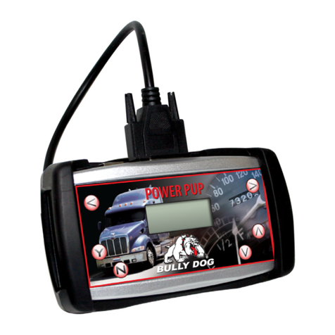
Bully Dog Power Pup User manual

Installation Steps
INSTALLATION MANUAL
Vehicle Application Part#
Dodge 5.9L Power Pup‘03-’04 42566
Dodge 5.9L Power PupW/ Outlook ‘03-’04 42569
Dodge 5.9L Power Pup‘04.5-’05 42567
Dodge 5.9L Power PupW/ Outlook‘04.5-’05 42570
Dodge 5.9L Power Pup‘06 42572

1
IntroductionPower Pup OperationOutlook InstallationOutlook OperationTroubleshootingWarranty & Disclaimer
TROUBLESHOOTING:
If you have questions during the installation of this product,
please visit www.bullydog.com/Product_Updates.php.
The latest version of these instructions can be found at the same
location. Please review the Troubleshooting section on page 21
before calling technical support to cover most common issues.
Technical support is available by calling 866-bullydog
(866-285-5936).
TABLE OF CONTENTS
Table of ConTenTs
INTRODUCTIONS ...............................................................................................PG 2
BILL OF MATERIALS...........................................................................................PG 2
POWER PUP OPERATION INSTRUCTIONS ................................................... PAGES 35
OUTLOOK MONITOR INSTALLATION...........................................................PAGES 613
Harness Description .........................................................................................................................Pg 6
Quick Overview..................................................................................................................................Pg 7
OBDII Harness Installation..............................................................................................................Pg 8
Outlook Main Harness .....................................................................................................................Pg 9
Pyrometer Installation ..........................................................................................................Pgs 10-12
Outlook Mounting .........................................................................................................................Pg 13
OUTLOOK OPERATING INSTRUCTIONS.....................................................PAGES 1419
General Display .......................................................................................................................Pgs 14-15
Main Menu................................................................................................................................Pgs 16-17
‘06 Instructions................................................................................................................................Pg 19
Pyrometer CalibrationProceidure............................................................................................ Pg. 20
RECOVER MODE............................................................................................... PG 20
TRANSMISSION RELEARN ................................................................................ PG 20
TROUBLE SHOOTING/FAQ................................................................................. PG 21
WARRANTY & DISCLAIMER .............................................................................. PG 22

2
Power Pup Operation Outlook Operation Outlook Operation Troubleshooting Warranty & Disclaimer
Introduction
INTRODUCTION
InTroduCTIon
Welcome to the world of increased power, performance and economy brought to you by the leader in perfor-
mance, Bully Dog Technologies. This set of instructions outlines have to install and operate both the Power Pup
downloader with and without the Outlook Monitor on the y.
Note: This instruction set and the downloader are made exclusively for the 5.9L Dodge Cummins engine ’03-’06. This
module will not work on any other vehicle other the stated make, model or year.
Note: There is no combo package for the ’06 5.9L Cummins. However, the Outlook Monitor (Part #40166) is compatible
and will work with the Power Pup.
BILL OF MATERIALS
1. Power Pup Downloader
2. OBD II Cable
3. OutLook Monitor with Main Harness
4. Pyrometer Probe
5. Windshield Mount
6. Pillar Pod Mount
7. OBD II Connector & Harness
8. Fuse Jack
9. 90° Connector
10. Zip Ties
TOOLS NEEDED
• Flat Head Screw Driver
• Phillips Screw Driver
• Wire Strippers
• Electric Drill
• 5/16”Drill Bit
• 1/8” Pipe Tap
• 9/16”Wrench
• 5/8”Wrench
• Electrical Tape
1.
2.
5.
7.
3.
6.
8.
10. 9.
4.

3
IntroductionOutlook InstallationOutlook OperationTroubleshootingWarranty & Disclaimer
HARNESS DESCRIPTION
Harness Description
OPERATING INSTRUCTIONS INITIAL DOWNLOAD
IMPORTANT: The steps on this page are performed on all part #s.
1. Make sure that your key is in the ignition in the o position before you plug the downloader into the vehicle.
The downloader will later prompt you to turn the key to the run position.
2. Connect the cable that comes with the downloader into the top of the downloader and then into the OB-
DII port. The OBDII port is the diagnostic port located underneath the dash on the driver side of the vehicle
(see OBDII Picture Below).
3. Watch the downloader light up to display its rst screen. Then follow the instructions given to you on the
screen of the downloader. The rest of these instructions cover the main points of operating the downloader,
but screen-to-screen guidance is listed on your Downloader.
If a Downloader is ever interrupted during
a download it may go into recovery mode.
refer to page 20 for recovery instructions.
Scroll Left Scroll Right
No/Exit Scroll Down
Yes/Enter Scroll Up
OBD II Port

4
Introduction Outlook Operation Outlook Operation Troubleshooting Warranty & Disclaimer
HARNESS DESCRIPTION
Harness Description
SCREEN OPTIONS
DOWNLOADER: Select this option to download a power program.
1. Select the “Downloads” option from the
main menu and turn the key to the run
position without starting the vehicle. The
downloader will then read and save the
vehicle’s stock information.
2. Once the downloader has saved your stock
information you will be prompted to se-
lect which power level you want. Choose
between Stock, Tow, Performance & Ex-
treme. Once you have chosen your power
level, follow the instructions given by the
downloader.
Horsepower Figures on this Chart are derived from a 2005 Dodge Cummins diesel with an automatic
transmission.
DESCRIPTION HORSEPOWER
GAINED RECOMMENDED USE
Extreme +140.2 HP
248.4 lbs. ft.
Racing, must use pyro and boost
gauges. Modied transmission
highly recommended.
Performance +77.9 HP
148.6 lbs. ft.
Driving and light towing. Must use
pyro and boost gauges.
Tow +53.8 HP
103.7 lbs. ft.
Light to heavy towing applications.
Pyro and boost gauges highly
recommended.
Stock +0 Choose the stock setting to return
to stock.

5
IntroductionPower Pup OperationOutlook OperationTroubleshootingWarranty & Disclaimer
INSTALLATION STEPS
Installation Steps
SCREEN OPTIONS
PTO CONTROLER
This feature is only available on‘03-’05 vehicles.The PTO Controler is an accessory tool that makes it possible
to raise and lower the vehicles idle RPMs. The PTO can be used to run accessory PTO devices such as winches
and generators.
USING THE PTO:
Once the PTO Controler is selected from the main menu the vehicle can be started, then press“Y”on the
downloader face to activate the process. Use the up and down arrows on the downloader face plate in-
crease or decrease the engine RPMs by increments of 100 RPMs up to 1900 RPMs. When nished using the
PTO Control, press“N”to stop the process and press“N”once more to exit.
RETURNING TO STOCK:
Plug in the downloader and select the download option from the main menu. Once in the power level selec-
tion menu, highlight 0 and press“Y”.Then follow the instructions set out on the downloader.When nished,
the downloader will have returned the vehicle to stock power level with the speed limiter intact and the
transmission shift patterns to stock.
DTC FUNCTION Diagnostic Trouble Code
Once selected from the main menu the DTC
function will display all diagnostic trouble
codes on your vehicle. This function allows
you to read and erase trouble codes o of the
vehicles ECU. To erase DTCs, simply press “Y”
and all DTC codes will be erased. If no DTCs are
displayed then just unplug the downloader
and cycle the key.

6
Introduction Power Pup Operation Outlook Operation Outlook Operation Troubleshooting Warranty & Disclaimer
Installation Steps
INSTALLATION STEPS
Note: If you purchased an OutLook with your Power Pup Included with this product are
three individual wiring harnesses. Please see the name, pictures, and descriptions of each
of the harnesses below. The instructions for your truck in this manual will refer to the dier-
ent harnesses by name.
OUTLOOK MAIN HARNESS: The OutLook monitor
main harness, page 2 #3, has an OutLook monitor on
one end and two green connectors, one with female
pins and male shell and one with male pins with a
female shell, at the other end. Of the green connec-
tors on the Outlook Main harness, the one with the
male pins and female shell connects to the OBD II
Harness as described above. The second green con-
nector, the one with the female pins and male shell, connects to a Sub-Harness if your truck uses one. Also
on the same end as the two green connectors, the OutLook Main harness has two sets of thermocouple wires
labeled Pyro 1 and Pyro 2, which can connect to two dierent pyrometers. Finally, on the OutLook Main harness
is a single black wire. This black wire comes from the factory connected to the Pyro 2 connections and is used as
a ground for unused pyrometer probe wires on the OutLook Main harness.
OBD II HARNESS: The OBD II Harness, page 2 #7,
has green a plug with female pins and male shell,
which connects to the OutLook Main harness that
has male pins and female shell. In addition to the
green plug on the OBD II Harness, the yellow wire
which is the Power Wire for the Outlook monitor. On
the opposite end of the OBD II Harness is the OBD II
connector, a rectangular plug in appearance from
which the OBD II Harness is named.
PYROMETER PROBE: The Pyrometer Probe, page
2 #4, is a steel braded cable with a pyrometer probe
tip on one end and red and yellow wire connections
on the opposite end.
OBD II Harness (#7)
OutLook Main (#3)
Pyrometer Probe (#4)
7
IntroductionPower Pup OperationOutlook OperationTroubleshootingWarranty & Disclaimer
PYRO Harness
OBDIIHarness
OutLookwithMain
Harness
(to exhaust manifold)
Data Link Plug
MAP Sensor Plug
Yellow PowerWire
fusebox
Installation Steps
INSTALLATION STEPS
OUTLOOK LOCATION OVERVIEW

8
Introduction Power Pup Operation Outlook Operation Outlook Operation Troubleshooting Warranty & Disclaimer
IMPORTANT: This step is performed with the OutLook installation.
Installation Steps
INSTALLATION STEPS
OBD II Port
INSTALLING THE OBD II HARNESS
In this step you will connect the OBD II plug, page 2 #7, connect the
power wire, and run the green connector through the re wall.
CONNECTING THE OBD II PLUG:
Plug the OBD II Harness into the OBD II Port located on the bottom side of the
dash on the driver’s side of the vehicle.
CONNECTING THE YELLOW POWER WIRE:
1. Prepare the yellow power wire by stripping the end of the wire about
¼”. Connect the blue 90° connector to the end of the Power Wire using
crimping pliers.The location may vary depending on vehicle make.
2. Locate the fuse box: Dodge fuse boxes are located under the hood inside
the engine bay. Please see your owners manual for more details on fuse
box locations. Once inside the fuse box, locate the appropriate fuse de-
picted in the vehicle-specic picture at right.
3. Remove the fuse, indicated in the picture and insert the fuse jack. Make
sure that the fuse jack is placed on the dead side of the fuse to ensure
that the OutLook monitor is protected by the fuse as well. Use a volt me-
ter to verify the dead side of the fuse. With the fuse pulled and the truck
powered on but not started, the volt meter should read 0 volts on the
fuse jack to ground. Problems that can occur if the incorrect fuse is used
for this connection: the power may stay on continuously even with the
key o; or, the OutLook monitor can receive power at the incorrect time
of the power-on/starting cycle of the vehicle.
4. Connect the yellow power wire to the fuse jack, place the fuse back into the slot, and close the fuse box.
wARNINg: For the OutLook to function properly, all fuses must be pushed in completely.
YellowPowerWirew/90ºconnector
Dodge: Fuse #28
OBD II Harness (#6)

9
IntroductionPower Pup OperationOutlook OperationTroubleshootingWarranty & Disclaimer
Installation Steps
INSTALLATION STEPS
INSTALLING THE OUTLOOK MAIN HARNESS
In this step you will run the OutLook Main harness,
page 2 #3, behind the weather stripping and connect
the OutLook Main harness to the OBDII Harness, page
2 #7.
1. For a clean install, rst peel-back the weather stripping next
to the dash on the driver’s side door.
2. Set the OutLook Monitor up on the driver’s side dash
and run the OutLook wires down behind the dash to
conceal the wiring. Remove the side dash panel to assist
in running the wiring. Reinstall the side dash panel and
the weather stripping.
3. On the inside of the cab, connect the green plug with
the female pins and male shell on the end of the OBDII
Harness to the green plug male pins and female shell
on the OutLook Main harness.
4. Go inside the cab of the vehicle to test the install
before going any further. Turn the ignition to the run
position: at this point the OutLook should light up and
display a vehicle selection screen. If the screen does not
light up, please refer to theTrouble Shooting section on
page 21.
5. Secure all wiring to ensure that it is safe from
extreme heat and moving parts using zip ties provided.
Be sure save some zip ties for the Pyrometer Probe or
Probes.
IMPORTANT: This step is performed on all vehicles.
Dodge Install
Harness Connections
OutLook Main Harness (#1)

10
Introduction Power Pup Operation Outlook Operation Outlook Operation Troubleshooting Warranty & Disclaimer
Installation Steps
INSTALLATION STEPS
IMPORTANT: This step is performed on all vehicles.
INSTALLING THE PYROMETER PROBE:
In this section of the manual you will drill and tap the
Pyrometer Probe in the exhaust, either Pre-turbo or
Post-turbo, and then connect the Pyrometer Probe
wires to the OutLook Main harness. Exhaust Gas Tem-
peratures indicate how hot the motor is getting and can
be used to set safety de-fueling parameters (see operat-
ing instructions “Set Pyrometer de-fuel Level”).
Post-turbo vs. Pre-turbo: You must decide between mounting the Pyro Probe either Post-turbo or Pre-
turbo. The dierence in location determines what temperatures will read on your OutLook.
It is recommended that you mount both a Pre-turbo and a Post-turbo Pyrometer Probe if a vehicle is running
more than 100 horsepower over Stock. On the OutLook display screen, Pyro 1 temps are constantly shown in the
bottom left quadrant (If you mount Pyro 1 in a Post-turbo location, the numbers in that quadrant will represent
Post-turbo).
A single Pyrometer Probe is the easiest install, and it is recommended that you install the probe Post-
turbo on the Dodge Cummins.
Whether you mount Post-turbo or Pre-turbo you need to monitor your temperatures; know what is safe
and when to back o. Use the Pyrometer Calibration Procedure on page 20 to gure out what your safety
limits are.
Pyrometer Probe (#3)

11
IntroductionPower Pup OperationOutlook OperationTroubleshootingWarranty & Disclaimer
wARNINg: If any debris such as drill bits, metal shav-
ings, spews etc. drops inside the manifold, we advise
disassembly of the turbo to remove the debris.
Installation Steps
INSTALLATION STEPS
TOOL TIP, PRETURBO MOUNT
When drilling into the exhaust manifold, metal spews, shavings, and broken drill bits can fall inside. This
can be hazardous to your turbo when the engine starts. Try doing four things to avoid this possible prob-
lem: One, use a high quality twist bit and a slow speed drill, about 500-800 rpm; Two, start with a small
pilot bit about 1/8”, then use the full 5/16” bit after the smaller one has punched through; Three, grease
your drill bit in addition to the normal lubricant, this will catch ying spews as they are cut; Four, just prior
to punching through into the inside of the manifold, start the engine and build up exhaust pressure on the
inside of the manifold (blows spews outside the manifold instead of letting them fall inside).
IMPORTANT: At least one Pyrometer Probe is required for OutLook installation.
PRETURBO MOUNT:
1. Drill a 5/16”hole into theExhaustManifold where all theexhaustrunnersofthemanifold cometogetherjust
before the turbo exhaust inlet.Then tap the hole with a 1/8”pipe tap and mount the Pyrometer probe in the
hole. Use a 9/16”wrench to tighten the probe holder or tube tting to the down tube.Then tighten the Pyro
Probe Cap to the holder using a 5/8”wrench.
2. Run the Pyro Cable up to engine bay and through the rewall to inside the cab so the end meets the end of
the OutLook Main harness. Use zip ties to secure the line.
3. Connect the Pyrometer to the OutLook Main harness: if you want Pre-turbo temperatures displayed in the
bottom left quadrant on the OutLook screen, connect the Pre-turbo Pyrometer connectors to Pyro 1 connec-
tors on the OutLook Main Harness. Connect the shorter wire from the Pyrometer to the longer wire on the
OutLook Main harness labeled Pyro 1 using a 5/16”wrench and a phillips screw driver. Connect the longer
wire from the Pyrometer to the shorter wire coming o the OutLook Main harness labeled Pyro 1.
4. If a second Pyro is not used, then connect the remaining Pyro 2 wires to the long black ground wire that is
sticking out from the Main Harness using the existing hardware. This will ensure that there is no electrical
interference between the Pyro connections. To further protect the connections, wrap all of the Pyrometer
connections in electrical tape.

12
Introduction Power Pup Operation Outlook Operation Outlook Operation Troubleshooting Warranty & Disclaimer
Installation Steps
INSTALLATION
POSTTURBO MOUNT:
1. Find a location on the exhaust pipe that is 3-6” downstream
from the turbo charger output. This may require removing the
down pipe in order to drill the hole. Then drill a 5/16”hole and
run a 1/8” pipe tap into the hole. Mount the Pyrometer Probe
in the threaded hole using a 9/16”wrench to tighten the probe
holder or tube tting to the down tube. Then tighten the Pyro
Probe Cap to the holder using a 5/8”wrench.
2. Run the Pyro Cable along the brim of the engine bay so the
end meets the end of the OutLook Main Harness and use zip ties
to secure the pyro line.
3. Connect the pyrometer end to the Outlook Main Harness. If you
want Post-turbo temperatures displayed in the bottom left quad-
rant on the OutLook screen, connect the Post-turbo connectors to
the Pyro 1 connectors on the OutLook Main Harness. Connect the
shorterwirefromthePyrometertothelongerwireontheOutLook
Main Harness labeled Pyro 1 using a 5/16”wrench and a Phillips
screw driver. Connect the longer wire from the Pyrometer to the
shorterwirecomingofftheOutLookMainHarnesslabeledPyro1.
4. IfasecondPyroisnotused,thenconnecttheremainingPyro2
wires to the long black ground wire that is sticking out from the
Main Harness using the existing hardware.This will ensure that
there is no electrical interference between the Pyro connections.
To further protect the connections, wrap all of the Pyrometer
connections in electrical tape.
TOOL TIP POSTTURBO MOUNT
When drilling into the exhaust pipe broken drill bits can fall
inside. Since it is after the turbo and no damage will be done.
Generally you still try to have as clean a drill hole as possible.
To avoid this possible problem use a high quality twist bit and
a slow speed drill, about 500-800 rpm and start with a small
pilot bit about 1/8”.
Securing pyro line
Pyrometer Wiring
IMPORTANT: At least one Pyrometer Probe is required for OutLook installation.
Dodge Post-turbo Mount

13
OUTLOOK INSTALLATION
IntroductionPower Pup OperationOutlook OperationTroubleshootingWarranty & Disclaimer
Installation Steps
OUTLOOK MONITOR MOUNTING INSTRUCTIONS
Bully Dog oers three dierent options for mounting the OutLook monitor, each lo-
cation option places the OutLook monitor in an easily accessed viewing area for the
driver.
WINDSHIELD MOUNT:
1. Locate the windshield mount included with the OutLook monitor.
This windshield mount does not come with mounting glue
that will stick metal to glass. This glue can be found at any
hardware store.
2. Place glue onto the window mount piece with the OutLook
monitor Holder detached from the windshield mount piece.
3. Hold the windshield mount piece on the windshield just to
the left of the steering wheel for one minute.
4. Let the glue set up as instructed by glue packaging and then
slide the OutLook monitor Holder onto the window mount
with the OutLook monitor attached.
PILLAR POD MOUNTING:
1.LocatetheOutLookpodmountcirclethatisincludedwiththeOutLook
monitor andattachtheOutLookmonitorto thepod mountcirclebyrun-
ningtheOutLookMainharnessthroughtherectangularholeinthecircle
and snapping the back onto the OutLook.
2.Followtheinstructionsforinstallingthesinglepillarpodmountthatis
included in the pillar mount package.
3. Run the OutLook Main harness wires down through the hole in the
pillar mount system and connect the OutLook to the other harnesses.
4. Finally, slide the pod mount circle with the OutLook attached into the
pillar mount hole.
OutLookPillarPod
This custom pillar pod is a
perfect t for your OutLook and
can be painted to match your truck’s
interior. Instructions for this mount
come with the pod.
OutLook Pillar Pod Mount (#6)
IMPORTANT: This step is performed on all vehicles.
OutLook Windshield Mount (#5)

14
Introduction Power Pup Operation Outlook Operation Outlook Operation Troubleshooting Warranty & Disclaimer
OUTLOOK INSTALLATION
Installation Steps
oPeraTInG InsTruCTIons:
This section of the manual describes how to use the joystick to navigate menus and control power lev-
els. Also included are descriptions of each of the menus and sub menus, as well as, showing how to do
a performance test.
NAVIGATION/JOYSTICK OPERATION
The joystick moves in four directions: up, down, left, and
right. The descriptions below provide an explanation
of what each direction is used for while navigating the
menus and selecting display options.
UP AND DOWN: There are two main uses of the joystick up
and down direction: One, scroll up and down in the general
displaytocontrolthevehiclepowerlevel.ScrollbetweenStock,
25%, 50%, 75% and 100%. If using the OutLook with a Triple
Dog Downloader, your settings will be Stock, Towing, Perfor-
mance and Extreme. Also, use the up and down directions to
scroll between menu items while in the main menu or any of
the sub menus.
RIGHT: Pressing right will take you from the general display
into the main menu. See the list of menu items on the next page. Pressing right will also select menu items and
navigate to sub-menus.
LEFT: Pressing left will take you from the main menu back into the general display. It is also used to reset any per-
formance test.
USING THE OUTLOOK / SELECTING THE CORRECT VEHICLE
The rst time you use the OutLook Monitor it will automati-
cally display theVehicle Selection Screen.The screen example
below shows what the vehicle selection screen looks like on
theOutLook. Itisextremely importantthatyouselectthecor-
rect vehicle application, because the OutLook will not work
correctly if it is not.
The dierent screen options describe dierent vehicle scenarios. Refer to the vehicle selection details on
the following page for clarication on when each option should be used. The option details correspond
with the screen options top to bottom.
Choose Your Vehicle
03-07 6.0L Ford w/ BD Mod
03-07 6.0L Ford w/ other
99.5-03 7.3L Ford w/ other
01-05 GM w /BD Module only
01-05 GM w / other or Stock
03-05 Dodge w/ BD Module
03-05 Dodge w / other

15
IntroductionPower Pup OperationOutlook InstallationTroubleshootingWarranty & Disclaimer
OPERATING INSTRUCTIONS
Operating Instructions
GENERAL DISPLAY
Once you have selected a vehicle upon initial use, the OutLook will then bring up the general display screen.
Below is an example of the general display screen. It has four quadrants which display vehicle diagnostics
andperformancetests.Italsohasapowerbarwhichdisplaysthepercentofpower beingused by thevehicle
fromaperformanceupgrade.
MAIN MENU ITEMS
Alloftheitemslistedinthisselection canbeaccessedonthe Out-
LookMonitorbypressingrightwhileinthegeneraldisplay.
ADJUSTOUTLOOKSPEEDOMETERTOTIRESIZE:
Oversized aftermarket tires will throw o the OEM speedometer read-
ing making it dicult to tell how fast you are really going.This feature
willallowyoutoprograminyourexacttiresize(28”upto44”)andview
an accurate speed reading on the OutLook screen in miles per hour.
Power Bar displays the % of HP & TQ gain provided
by aftermarket performance product
Top Left Quadrant
displaysuser preset
options
BottomLeftQuadrant
alwaysdisplaysthe
Pyro1Temperature
Reading, whichcor-
relatestoPyro1on the
OutLook MainHarness.
Top Right Quadrant
displaysuser preset
options
BottomRight
Quadrant
displaysuser preset
options
Main Menu
Adj Speedmtr to Tire Size
Set Top Left Display
Set Bottom Right Display
Set Pyro De-fuel level
View Last Ten Readings
View All-time Highs
View Current Settings
View Peak Values
Clear Saved Peaks
Vehicle Selection Screen
Set Transmission Defuel
Display & Erase DTC’s
Adj Speedmtr to Tire Size
28.00 inches
28.25 inches
28.50 inches
28.75 inches
29.00 inches
29.25 inches
29.50 inches
IMPORTANT: These Tire size calibrations will not be accurate if adjustments have already been made with a Triple
Dog Downloader or other speed-o recalibration methods.

16
Introduction Power Pup Operation Outlook Operation Outlook Operation Troubleshooting Warranty & Disclaimer
OPERATINGINSTRUCTIONS
Operating Instructions
MAIN MENU ITEMS
SET TOP LEFT DISPLAY: Select this to enter a sub-menu with a list of OutLook Display Options that you select
to view in the top left display quadrant of the OutLook Screen. All of the OutLook Display Options are listed in this
instruction set with options specic to this make, model, and year of vehicle.
SETTOP RIGHTDISPLAY:Selectthistoenterasub-menuwithalistofOutLookDisplayOptionsthatyoucanselect
to view in the top right display quadrant of the OutLook Screen. All of the OutLook Display Options are listed in this
instruction set with option specic to this make, model, and year of vehicle.
SET BOTTOM RIGHT DISPLAY: Select this to enter a sub-menu with a list of OutLook Display Options that you
canselectto viewinthe bottom rightdisplayquadrant ofthe OutLook screen.Allof the OutLookDisplayOptions are
listed in this instruction set with options specic to this make, model, and year of vehicle.
The chart below depicts the features available for display in the Top Left, Top Right, and Bottom
Right Quadrants of the OutLook General Display Screen.
NOTE: The BOTTOM LEFT DISPLAY quadrant always displays Pyro #1. This quadrant item cannot be changed.
FEATURES DODGE
On The Fly Adjustability X
Pyrometer Probe Defuel X
Transmission Temperature defuel ‘06 only
Display and erase DTCs ‘06 only
Boost Pressure X
Dual Pyrometer Probe (2) X
Accurate Speed Display (MPH) X
Engine RPMs ‘06 only
Throttle Position ‘06 only
Coolant Temperature X
Transmission Temperature ‘06 only
Injection Control Pressure X
Horsepower and Torque X
0-60 times (MPH) X
1/4 Mile Time X
Peak Boost X
Peak Pyro X
Peak Horsepower X
Peak Torque X
Fastest 0-60 X
Fastest 1/4 mile X

17
IntroductionPower Pup OperationOutlook InstallationTroubleshootingWarranty & Disclaimer
OPERATING INSTRUCTIONS
Operating Instructions
View Last 10 Readings
Quarter Mile Times
0-60 Times
Peak Boost / Start Cycle
Peak Pyro / Start Cycle
Clear Top Ten Values
View All-time Highs
Quarter Mile Times
0-60 Times
Clear Top Ten Values
Set Pyrometer Probe De-fuel level
900º
950º
1000º
1050º
1100º
1150º
1200º
Set Transmission De-fuel level
180º
190º
200º
210º
220º
230º
240º
MAIN MENU ITEMS
SET PYROMETER PROBE DEFUEL LEVEL: With this menu
option a list of temperatures ranging from 900˚F up to 1700˚F is
presented. Based upon where you have installed the Pyrometer
Probe (see installing the Pyro Instructions), you will use this op-
tiontoselectthehighesttemperatureyoueverwantyourexhaust
gas to reach when de-fueling. We recommend that you use our
Pyrometer Probe Calibration Procedure to nd out what your Pyrometer Probe de-fuel level will be. Once a de-fuel
level is put in place, if the Exhaust GasTemperatures (EGT’s) reach a level greater than or equal to the set level, the
OutLook willautomaticallylower thehorsepower and,inturn,bringEGT’s backdown toasafe level.Thisfeaturehas
been designed to save the integrity of an engine by preventing unsafe engine temperatures.
The default de-fuel level temperature is 1200˚F. If you do not have a Pyrometer Probe hooked up to the
OutLook,itactsasthoughyourEGT’sarebelow100°Fandthissafetyfeaturewillnotwork.Thereforeyour
engineissusceptibletooverheatingwiththeadditionofperformanceupgrades.
SET TRANSMISSION DEFUEL LEVELS Use this feature to pre-
set an automatic de-fuel level for your vehicle. We recommend
setting a de-fuel temperature level of 230ºF.The default de-fuel
level is set to 180 ºF.
DISPLAY AND ERASE DTC’S If you see a check engine light come on or the vehicle seems to be
running abnormally, you will want to use this feature to see if any Diagnostic Trouble Codes ap-
pear. Use this feature to display the codes and also to erase them from the vehicle’s computer. If
the vehicle has recurring trouble codes, research the origin of the code and consult a tech sup-
port expert on how to x the code. For a full listing of Diagnostic Trouble Codes go to:
www.bullydog.com/DTC.php
VIEW LAST 10 READINGS This feature lets you view the last
Pyro readings taken per key cycle, the last 10 Pyro readings
taken per key cycle, the last 10 boost readings per key cycle, and
if the features are available to your vehicle it will show you your
last 10 quarter mile runs and 0-60 runs. You can also erase the
last ten readings. See Clear Peak Values below to erase.
VIEW ALL TIME HIGHS Select this and then choose to see your
ve all time best 0-60 times and quarter mile times. You can
also choose to erase your all time highs to make room for new
ones. See Clear Peak Values below to erase.
NOTE: Pyrometer Probe Calibration Procedure is found on page 24.

18
Introduction Power Pup Operation Outlook Operation Outlook Operation Troubleshooting Warranty & Disclaimer
OPERATINGINSTRUCTIONS
Operating Instructions
CURRENT SETTINGS
Truck Selected:
03-05 5.9L Dodge w / BD Mod
Tire Size:
32 Inches
Emergency Power Cuto:
1250˚F
CURRENT PEAKS
Boost: 0 PSI
Pyrometer Probe: 000˚ F
Horsepower 0.0 HP
Torque: 0.0 ft-lbs
0-60 Time: 0.00 Seconds
1/4 Mile Time: 0.00 Seconds
MAIN MENU ITEMS
VIEW CURRENT SETTING: This feature allows you to see how
the OutLook has been set up to work with the vehicle. It will
display what truck type was selected, what the tire size was set
to and what the emergency de-fuel level is set to. This makes it
simple to make sure you have these standards set up correctly.
VIEWPEAKVALUES: This feature will show you all of the single
all time highs for your vehicle on a single screen.
CLEAR PEAK VALUES: This will enable you to erase the peak
values that are saved in the OutLook and displayed when you select the View Peak Values main menu op-
tion. Clearing the peak values will free up the OutLook to record new values lower than the previously saved
peaks.
VEHICLE SELECTION SCREEN: This is the same screen that ap-
pears when the OutLook gets installed for the rst time. Use this
feature if the wrong setting is set or if the OutLook is transferred
to a dierent brand of vehicle.
Choose Your Vehicle
03-07 6.0L Ford w/ BD Mod
03-07 6.0L Ford w/ other
99.5-03 7.3L Ford w/ other
01-05 GM w /BD Module only
01-05 GM w / other or Stock
03-05 Dodge w/ BD Module
03-05 Dodge w / other

19
IntroductionPower Pup OperationOutlook InstallationTroubleshootingWarranty & Disclaimer
OPERATING INSTRUCTIONS
Operating Instructions
IMPORTANT: Skip these steps if your vehicle is not a ’06 Dodge Cummins.
SPECIFIC INSTRUCTIONS FOR‘06 DODGE CUMMINS:
WhenusingtheOutLookonthe‘06DodgeCumminsthersttimetheOutLookisinstalled,immediatelyafter
the vehicle is selected, the OutLook will undergo a vehicle sequence test. The screens below illustrate exactly
whatisseenduringthetest.
SEQUENCE INSTRUCTIONS:
1. When this rst screen appears simply
press right on the joystick to continue the
sequence test. If you have previously com-
pleted the sequence test, then recycle the
key. If the screen repeatedly appears, call
Bully DogTechnical Support.
2. On the second sequence test screen sim-
ply press right on the Joystick to complete
the test. After the test has been complet-
ed, then the OutLook will navigate to the
General Display Screen.
Other manuals for Power Pup
4
Table of contents
Other Bully Dog Automobile Electronic manuals

Bully Dog
Bully Dog Watchdog User manual

Bully Dog
Bully Dog Power Pup User manual

Bully Dog
Bully Dog Power Pup User manual

Bully Dog
Bully Dog Triple Dog Downloader User manual

Bully Dog
Bully Dog Triple Dog GT Gas User manual

Bully Dog
Bully Dog Power Pup User manual

Bully Dog
Bully Dog 50 State GT Diesel User manual

Bully Dog
Bully Dog Power Pup User manual

Bully Dog
Bully Dog 40417 User manual