BHM
03/02/17
NTV-DOC291
Agreement: End user agrees to use this product in compliance with all State and Federal laws. NAV-TV Corp. would not be held liable for
misuse of its product. If you do not agree, please discontinue use immediately and return product to place of purchase. This product is
intended for off-road use and passenger entertainment only.
3 | P a g e
1. Remove the factory screen, and radio (CD player). Connections for this installation
require both locations to be accessible.
2. Behind the screen, locate the OEM blue GVIF video connector. Connect the provided
GVIF-OUT Cable to the screen where the OEM video cable was connected previously.
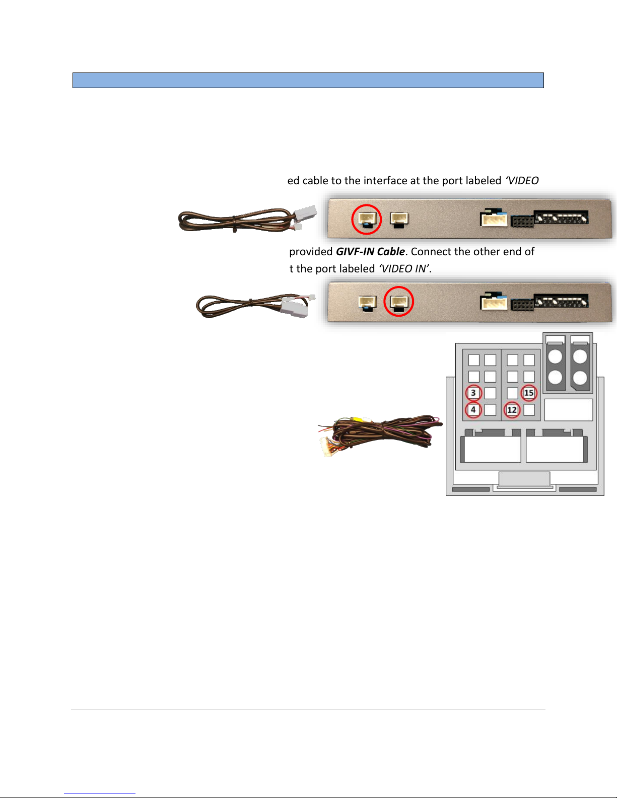
3. Connect the other end of this provided cable to the interface at the port labeled ‘VIDEO
OUT’.
4. Connect the OEM video cable to the provided GIVF-IN Cable. Connect the other end of
this provided cable to the interface at the port labeled ‘VIDEO IN’.
5. With the provided Power/CAN Harness, Connect the following
wires to the radio’s main power plug:
a. Black wire to PIN 15 (ground)
b. Red wire to PIN 12 (12v constant)
c. Blue wire to PIN 3 (CAN HIGH)
d. White wire to PIN 4 (CAN LOW)
6. Optional: If desired, the green wire may be used as a trigger for forcing rear camera or
AUX video input (see OSD menu settings)
7. Optional: The purple wire may be used to power a (single) rear camera (12v + reverse
ONLY, 500 mA MAX )
8. Optional: Connect the provided AUX Video Input cable RCA to the port labeled ‘AV IN’ if
adding a front camera or aux composite video input.
9. Connect the main Power/CAN harness to the interface at the proper port.
10. Reconnect all plugs to the radio and screen and proceed to ‘GVIF-Volvo Operation’.
NOTE: CAN2 wires (orange & green) are NOT used for this installation.