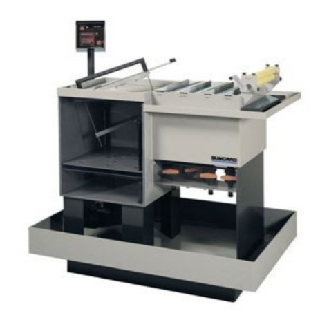
Bungard StenPrint 3000 User manual

Stencil Printer StenPrint 3000

3
© 22.02.2017 Bungard GmbH & Co. KG
Table of Content
Introduction 4
General 5
......................................................................................................................................................... 5Intended use
......................................................................................................................................................... 6Standard text symbols
......................................................................................................................................................... 7Customer service
......................................................................................................................................................... 7Warranty and Liability
Safety 8
......................................................................................................................................................... 8Responsible behavior
......................................................................................................................................................... 8User training
......................................................................................................................................................... 9Safety and maintenance
......................................................................................................................................................... 9Operating conditions
......................................................................................................................................................... 9Operating and maintenance
System components 11
......................................................................................................................................................... 11Adjusting knobs for X, Yand Theta adjustments
......................................................................................................................................................... 11Adjusting knob 1a
......................................................................................................................................................... 11Adjusting knob 1b
......................................................................................................................................................... 12Frame fixture
......................................................................................................................................................... 13Tilt m echanism
.................................................................................................................................................. 13Adjusting the tilt mechanism
......................................................................................................................................................... 14Parallel stencil lift
......................................................................................................................................................... 15Adjustable PCB thickness
......................................................................................................................................................... 16Supporting points
......................................................................................................................................................... 17Scraper
......................................................................................................................................................... 18Optional accessories
......................................................................................................................................................... 18Fr am e
.................................................................................................................................................. 18Stencil holder frame
.................................................................................................................................................. 19Assembling the stencil
.................................................................................................................................................. 20Assembling the stencil holder frame
.................................................................................................................................................. 21Stencil clamp frame
.................................................................................................................................................. 22Mounting the stencil
.................................................................................................................................................. 24Mounting the stencil clamping frame
.................................................................................................................................................. 25Stencil clamping for fixed frames
.................................................................................................................................................. 25Mounting the stencil clamping
.................................................................................................................................................. 26Mounting the frame
......................................................................................................................................................... 27Hand scrapers
......................................................................................................................................................... 28PCB holders
.................................................................................................................................................. 28Magnetic holders for double-sided printing
Accessories and spare parts 30
Technical data 31
......................................................................................................................................................... 31903.005 - Stencil Printer
......................................................................................................................................................... 31903.203 - Stencil holder frame
......................................................................................................................................................... 31903.204 - Stencil clamp frame
......................................................................................................................................................... 31903.205 - Stencil clamp for stencils in fixed frames
......................................................................................................................................................... 31903.103 - Magnetic holders for double-sided printing
4Instruction manual
© 22.02.2017 Bungard GmbH & Co. KG
1Introduction
BUNGARD GmbH & Co. KG (called „BUNGARD“ in the following text) reserves the right to
change or enhance its machines or machine specifications according to its judgment, if
necessary. BUNGARD cannot be held responsible to implement aforesaid changes into
machines sold already.
BUNGARD products and services are liable to the current prices and conditions, which
are subject to change.
The instructions and definitions in this document are also subject to change and mark no
assurance on the part of BUNGARD. The software described in this document is supplied
to the customer within the limits of the licensing agreement. Copying the software onto a
separate data carrier is illegal, except in terms of being explicitly permitted in the licensing
agreement. The customer is authorized to make a personal backup copy of the software.
This document may not be reproduced or transferred/broadcasted (as a whole or partially)
using electrical or mechanical measures (including photo copies) for any purpose without
the approval of FRITSCH GmbH.
© 2017 BUNGARD GmbH & Co. KG – all rights reserved.
StenPrint3000®is registered trademark of BUNGARD GmbH & Co. KG.
Many descriptions, that manufacturers and traders use to brand their products, are
claimed as trademarks. BUNGARD has listed all trademarks known to itself in the
preceding paragraph.

5Instruction manual
© 22.02.2017 Bungard GmbH & Co. KG
2General
Before installation, connection to the mains or starting this equipment please read all of
these instructions.
These instructions should always be available to operators, as they are necessary for the
safe operation of this equipment and because they can assist in diagnosing any problems
that might occur.
This manual contains informations of the stencil printer and is the translated English
version.
For use by the user and associated personnel.
Copying and distribution is permitted only for internal company use.
2.1 Intended use
The stencil printer is constructed for the following intended use:
the manual application of solder paste on PCBs
Only in the manual described utilization is allowed.
The BUNGARD GmbH & Co. KG assumes no liability for damages made by not correct
use of the machine.

6Instruction manual
© 22.02.2017 Bungard GmbH & Co. KG
2.2 Standard text symbols
This manual uses different symbols to characterize important information:
Attention
This symbol shows the user, that the FEEDER could be damaged if the user doesn’t
follow the exact procedure.
Warning
Marks, if the user could be hurt or the machine could severely damaged when the user
doesn’t follow the exact procedure.
Important
The marked information should be read carefully to ensure a correct function of the
machine.
Tips and Tricks
This symbol marks useful information and helpful hints for the user.

7Instruction manual
© 22.02.2017 Bungard GmbH & Co. KG
2.3 Customer service
There is a return to factory service available for BUNGARD SMD Pick & Place equipment.
In the unlikely event of your machine needing to be repaired please send it to your supplier,
area representative or direct to us.
To accept a repair item, we use a RMA form. Please request this form before returning
the goods to us. Without RMA we can not ensure that the repairs are carried out correctly.
For a quick and inexpensive repair a meaningful error description is essential. Please refer
to this RMA form.
2.4 Warranty and Liability
Please regard the “Sales terms and delivery conditions”. These are available after
fulfillment of the contract. We don't furnish a guarantee or warranty in cause of damages
at material or hurts of people because of
Incorrect use of the machine
Wrong setup, installing and operating of the machine or incapable service
Use of the machine with defective safety equipment
Nonobservance of the service manual in regard to transport, stocking, setup, installation
and service of the machine
Unlicensed modifications at the machine
Incorrect or incomplete repairs
Destructive force effect at the machine in cause of foreign objects or external use of
force
Use of non-original spare parts

8Instruction manual
© 22.02.2017 Bungard GmbH & Co. KG
3Safety
BUNGARD machines may only be operated, repaired and maintained by skilled personnel.
3.1 Responsible behavior
Consider please the following guidelines for responsible behavior:
While maintenance, follow the instructions in the attachment.
Keep away from moving parts.
Before operating or try to repair the machine, all manuals and signs has to be read and
understood.
Make sure, that the relevant qualifications and the functions and safety components of
the machine are present. If it is necessary, ask a superior.
Do not misuse the machine. Apply the machine only after its sense of use according to
the manual.
Repairing the devices is only permitted to service technicians of the BUNGARD GmbH
& Co. KG.
Consider if necessary also the special safety regulations of your country.
3.2 User training
Only trained and competent persons are allowed to actuate the machine.
The persons in authority for rebuild, installation, operation, service and repair have to be
exactly identified.

9Instruction manual
© 22.02.2017 Bungard GmbH & Co. KG
3.3 Safety and maintenance
Warning
To maintain the required operational safety please note the following:
Keep parts of the body away from moving parts.
Non conformance with these instructions can lead to death, severe injuries or
considerable damage!
Do not open the housing.
Do not use the equipment for purposes other than those it was intended for as outlined
in the operating instructions.
The repair of this equipment may only be carried out by persons authorised by the
manufacturers BUNGARD GmbH & Co. KG.
Please also observe any relevant country specific safety rules.
3.4 Operating conditions
Please consider the following operation conditions for the stencil printer:
Adequate carrying capacity of the table and space
Ambient conditions: 20°C...25°C, dust and oil-free air as possible.
3.5 Operating and maintenance
The stencil printer does not contain any parts requiring routine maintenance.
To ensure trouble free operation over a number of years please observe the following
points:
Please keep the work space clean. Contamination of the stencil printer could lead to
premature wear. Examples: corrosion of metal parts or erosion of moving parts.
Please check regularly the moving parts of free movement. If there is a rough-running
you can use a lubricant.

10 Instruction manual
© 22.02.2017 Bungard GmbH & Co. KG
Please note !
Should you have any problems with your stencil printer or need some advice on its use we
shall be happy to be of assistance to you.
The SD903.005 does not contain any parts requiring routine maintenance.

11Instruction manual
© 22.02.2017 Bungard GmbH & Co. KG
4System components
The stencil printer comprises several system components that are briefly described in the
following.
4.1 Adjusting knobs for X, Y and Theta adjustments
4.1.1 Adjusting knob 1a
The X direction of the table can be adjusted with adjusting knob 1a.
4.1.2 Adjusting knob 1b
The Y direction of the table can be adjusted by turning the two adjusting knobs 1b in the
same direction.
The Theta rotation can be set by turning the two adjusting knobs 1b in opposite
directions.

12 Instruction manual
© 22.02.2017 Bungard GmbH & Co. KG
4.2 Frame fixture
The stencil printer can be equipped with different frames for the fixture of stencils by way
of its frame fixture (2).
The different frames available for fixing the stencils in place are listed under Optional
accessories.
Tips and tricks
The frame fixture can be assembled in various positions where needed (see
red arrows in the picture).
Fr am e fixture

13Instruction manual
© 22.02.2017 Bungard GmbH & Co. KG
4.2.1 Tilt mechanism
The frame fixture is equipped with a tilt mechanism in order to be able to tilt the frame with
the stencil upwards. This is necessary to place the PCB in the stencil printer.
When the tilt mechanism is opened, it clicks into the upper position
A locking knob (3) has to be pulled to close the mechanism.
Tilt m echanism
Attention
The tilt mechanism must be held open with your other hand whilst pulling the
locking knob to prevent it from falling shut.
4.2.1.1 Adjusting the tilt mechanism
The degree of tilt of the stencil printer's tilt mechanism can be altered by way of an
adjustment screw (5). By doing so, this enables the stencil printer to adapt to various
stencil frames. With frames of varying weights, the tilt mechanism must be adjusted such
that the stencil is positioned parallel to the PCB.
Adjusting the tilt m echanism

14 Instruction manual
© 22.02.2017 Bungard GmbH & Co. KG
4.3 Parallel stencil lift
The stencil printer is equipped with a parallel stencil lift.
Rotating the lever (4) a half turn in clockwise direction causes a lift of 2mm.
Stencil lift
bottom
Stencil lift top
The lever has a locking device at the top and bottom to enable repeated lifting.

15Instruction manual
© 22.02.2017 Bungard GmbH & Co. KG
4.4 Adjustable PCB thickness
The stencil printer can be adjusted to varying PCB thicknesses.
The stencil printer can be adjusted to the thickness of the PCB by way of lever (4).
oThe thickness of the PCB is reduced by turning the lever (4) clockwise.
oThe thickness of the PCB is increased by turning the lever anticlockwise.
oA quarter turn corresponds with a change in thickness of 1 millimetre.
After the right PCB thickness has been set, the locking device of the lever can be
loosened using a 3mm Allen key.
Locking device
loosened
Lever
rem oved
Lever
adjusted
The lever (4) can now be removed and adjusted.
After that, the lever (4) can be clamped back in using the 3mm Allen®key.
Important
Whilst the locking device of the lever (4) is being tightened, it must be pushed
downwards.

16 Instruction manual
© 22.02.2017 Bungard GmbH & Co. KG
4.5 Supporting points
The stencil printer has supporting points so that the stencil remains parallel to the stencil
printer whilst the soldering paste is being applied with the scraper. These supporting
points must be adjusted before printing such that they support the frame used.
The supporting points comprise two knurled screws, the height of which can be set as
required. As soon as the screws have been adjusted, they can be secured against moving
by means of knurled nuts.
Supporting points

17Instruction manual
© 22.02.2017 Bungard GmbH & Co. KG
4.6 Scraper
The stencil printer is supplied together with a scraper.
The scraper is for applying the soldering paste to the stencil.
Scraper
Tips and tricks
There are various types of hand scrapers available to improve the printing
process.

18 Instruction manual
© 22.02.2017 Bungard GmbH & Co. KG
4.7 Optional accessories
4.7.1 Frame
There are various frames available for holding stencils
The various frames are listed in the following:
4.7.1.1 Stencil holder frame
The simplest way of holding a stencil for the stencil printer is the stencil holder frame.
903.203 - Stencil holder fr am e
It is meant to hold the stencil in place without having to use clamps.
The holder frame was developed for the holding of so-called “prototype stencils”.
oThese are frequently available from PCB suppliers at low cost.
Due to the fact that the “prototype stencils” are slightly larger than the PCB to be printed
and that they have no holes for holding them, the stencils are held in place by clamping.
Important
Depending on the size of the stencil, the parallel stencil lift cannot be used
optimally.
Attention
No guarantee can be provided that all available “prototype stencils” can be
held in place with the stencil holder frame..

19Instruction manual
© 22.02.2017 Bungard GmbH & Co. KG
4.7.1.1.1 Assembling the stencil
The clamping screws must first be loosened (see red arrows in the picture) with a 3mm
Allen®key before the stencil can be placed in the frame.
Next, the stencil can be pushed under the clamping strip.
Now the clamping screws can be tightened again so that the stencil is firmly in place.
oIt is easier to tighten the clamping screws when the frame is turned over.
Clam ping the stencil
The stencil holder frame can now be assembled into the stencil printer

20 Instruction manual
© 22.02.2017 Bungard GmbH & Co. KG
4.7.1.1.2 Assembling the stencil holder frame
The stencil holder frame is screwed onto the frame holder for assembling into the
stencil printer.
The frame holder has several holes for affixing the stencil holder frame (see red arrows
in the picture).
oThe stencil holder frame can be affixed to the holder at different heights depending
on the thickness of the PCB and the PCB holder used.
Fr am e holder
The threaded pins of the stencil holder frame are inserted into the corresponding holes
of the holder to affix it.
Now the frame can be held in place with the corresponding knurled nuts (see red arrows
in the picture).
As sem bled s tencil holder fr am e

21Instruction manual
© 22.02.2017 Bungard GmbH & Co. KG
4.7.1.2 Stencil clamp frame
With the stencil clamp frame, it is possible to hold and clamp “prototype stencils”.
903.204 - Stencil clam p fram e
It is meant for holding the stencils by clamping them from two sides.
The clamp frame was developed to holding so-called “prototype stencils”.
oThese are frequently available from PCB suppliers at low cost.
Due to the fact that the “prototype stencils” are slightly larger than the PCB to be printed
and that they have no holes for holding them, the stencils are held in place in the clamp
frame by two clamps.
Attention
No guarantee can be provided that all available “prototype stencils” can be
held in place with the stencil clamp frame.
Important
The magnetic holders are required to use the stencil clamp frame in the
stencil printer for double-sided printing.
Table of contents
Other Bungard Industrial Equipment manuals

Bungard
Bungard CCD/2 User manual

Bungard
Bungard Jet 34d User manual

Bungard
Bungard SMT3000 ECO LIGHT Plus User manual

Bungard
Bungard RDC 30 User manual

Bungard
Bungard EXP3040LED User manual

Bungard
Bungard RDC 21-K User manual

Bungard
Bungard CCD/2 User manual

Bungard
Bungard Splash User manual

Bungard
Bungard DL 500 User manual
Popular Industrial Equipment manuals by other brands

Hainbuch
Hainbuch TOPlus mini operating instructions

R.V.R. Elettronica
R.V.R. Elettronica PJ5KPS User's & technical manual

Baileigh Industrial
Baileigh Industrial DEM-1717 operating instructions

deconta
deconta D 610 instruction manual

Huawei
Huawei SUN2000-4.95KTL-JPL0 user manual

Wachs
Wachs DW Guillotine 208 user manual