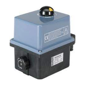
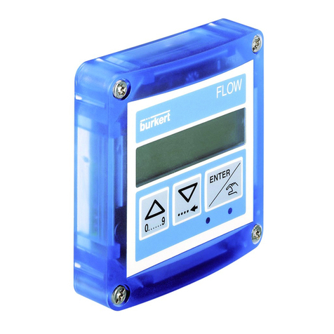
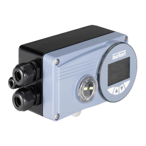
Burkert 8750 User manual
Other Burkert Controllers manuals
Burkert
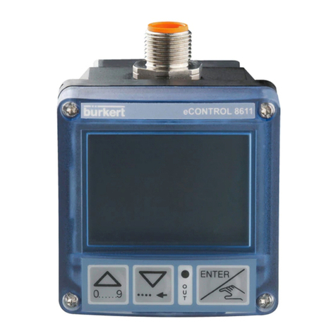
Burkert eCONTROL 8611 User manual
Burkert
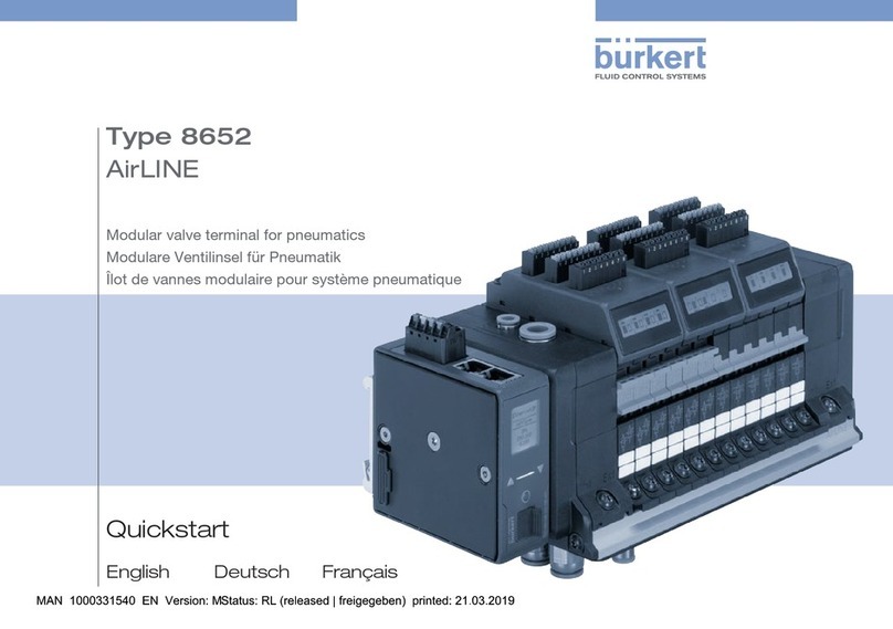
Burkert AirLINE 8652 User manual

Burkert
Burkert 8605 Series User manual
Burkert
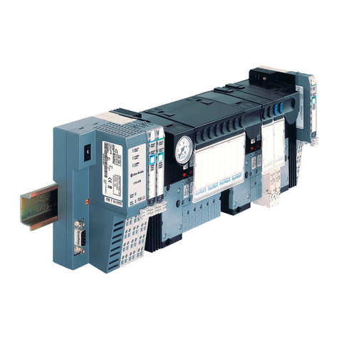
Burkert 8644 AirLINE User manual
Burkert
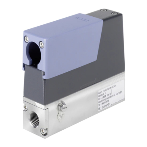
Burkert 8742 Operating manual
Burkert
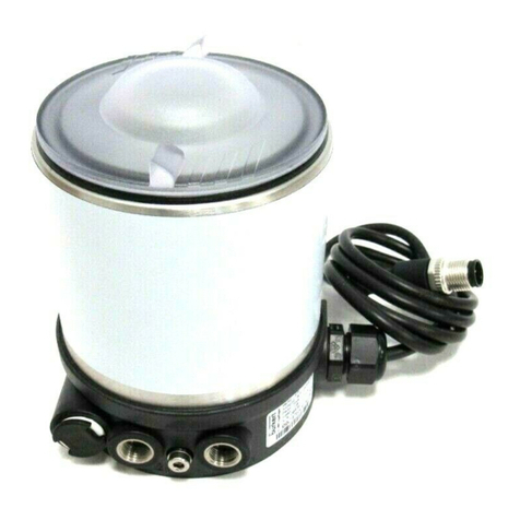
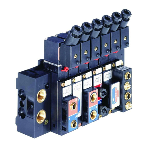
Burkert 8691 REV.3 User manual
Burkert
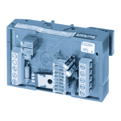
Burkert 5470 User manual
Burkert
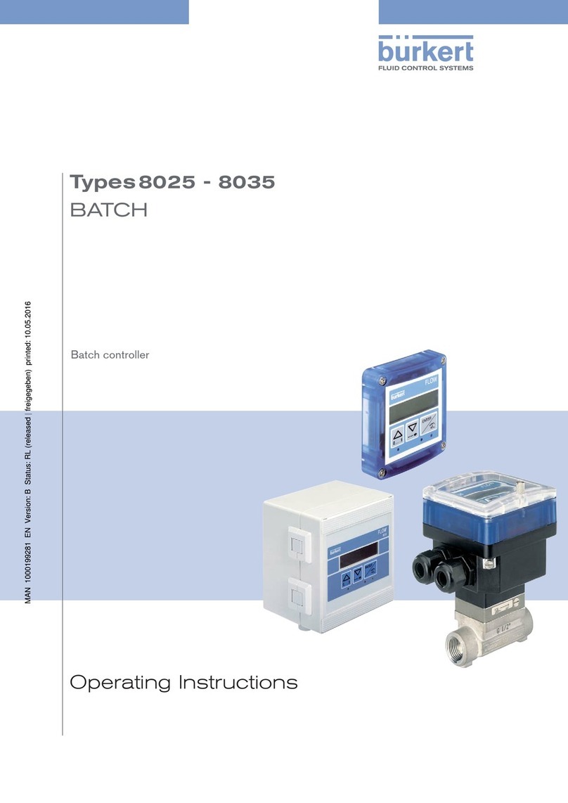
Burkert 1094 Series User manual
Burkert
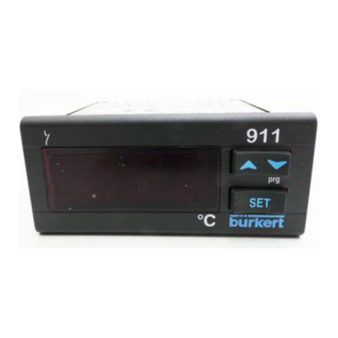
Burkert 8025 Series User manual
Burkert
Burkert 0911 User manual
Burkert
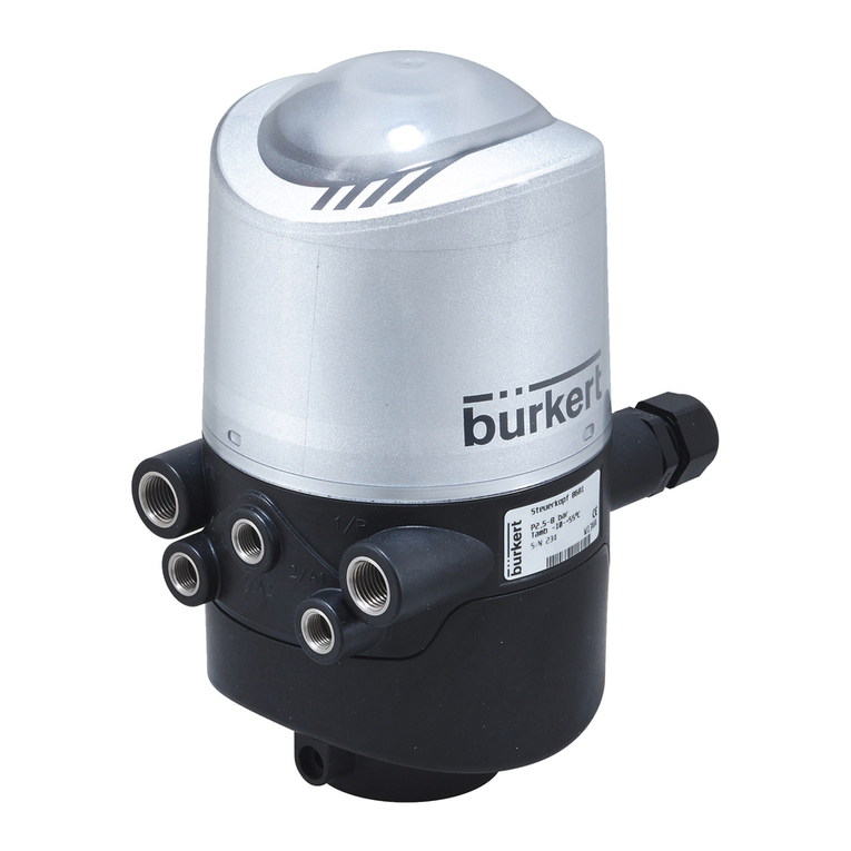
Burkert 8681 User manual

Burkert
Burkert 8025 Series User manual
Burkert
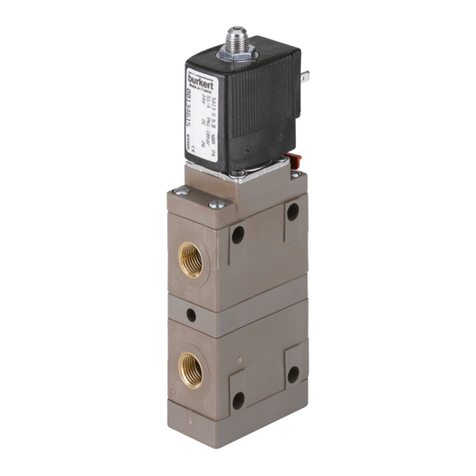
Burkert 5413 User manual

Burkert
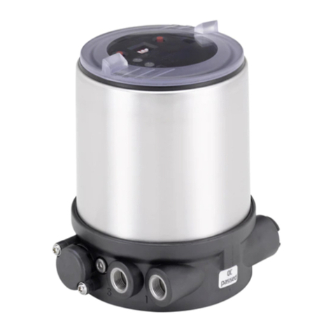
Burkert 6626 TwinPower User manual
Burkert
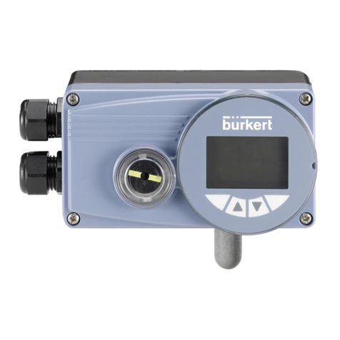
Burkert Positioner TopControl Basic 8694 User manual
Burkert
Burkert 8793 User manual
Burkert
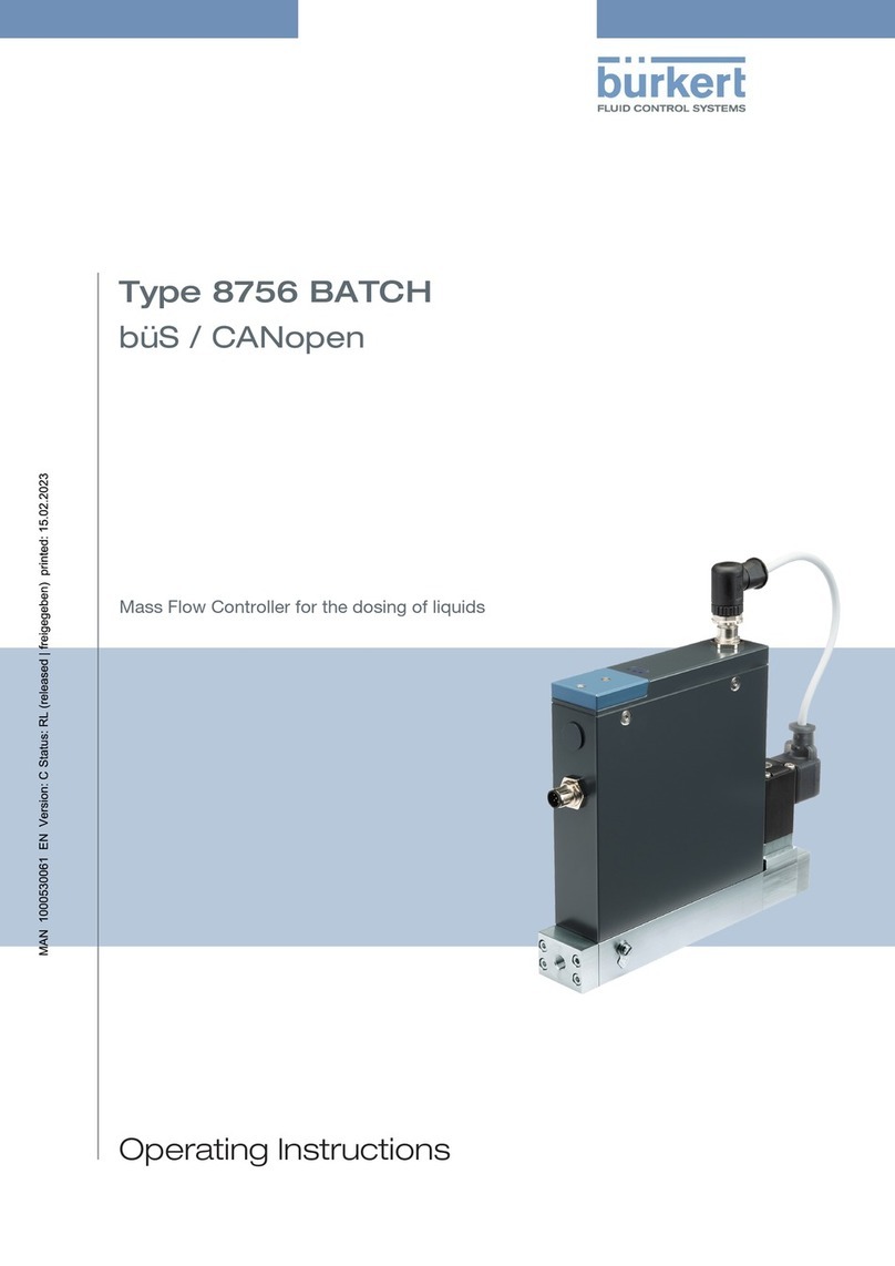
Burkert 8756 BATCH User manual
Burkert
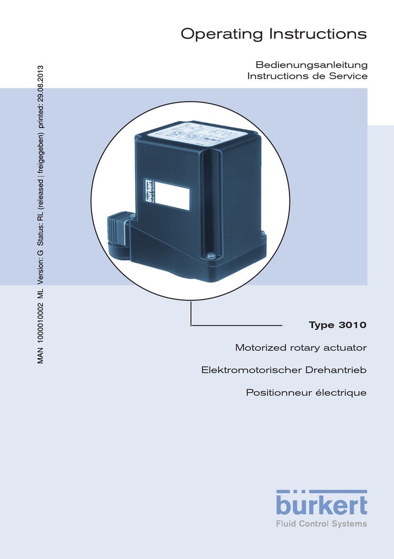
Burkert 3010 User manual

Burkert
Burkert 8691 User manual

Burkert
Burkert 8745 MFM Ethernet User manual
Popular Controllers manuals by other brands

Digiplex
Digiplex DGP-848 Programming guide

YASKAWA
YASKAWA SGM series user manual

Sinope
Sinope Calypso RM3500ZB installation guide

Isimet
Isimet DLA Series Style 2 Installation, Operations, Start-up and Maintenance Instructions

LSIS
LSIS sv-ip5a user manual

Airflow
Airflow Uno hab Installation and operating instructions
