manuals.online logo
Brands
  1. Home
  2. •
  3. Brands
  4. •
  5. BW Technologies
  6. •
  7. Gas Detector
  8. •
  9. BW Technologies GasAlertClip Extreme H2S User manual

BW Technologies GasAlertClip Extreme H2S User manual

GasAlertClip English Instruction Sheet
D2087/2 Page 1
Trimmed and folded dimensions: 4.125 (w) x 5.875 (H)
BW TECHNOLOGIES
GasAlertClip
2 Year Gas Detector
Instruction Sheet
Introduction
The GasAlertClip gas detector (“the detector”) warns of hazardous gas at
levels above (below for oxygen deficiency) a factory set alarm setpoint. The
detector is a personal safety device that stores and transmits gas alarm
event data. It is your responsibility to respond properly to the alarm.
Models with internal vibrator
alarm and event logging Gas Monitored
GA24A-H-EL hydrogen sulfide (H2S)
GA24A-M-EL carbon monoxide (CO)
GA24A-S-EL sulfur dioxide (SO2)
GA24A-X-EL oxygen (O2)
GA-TC-1 Test Cap Accessory
The test cap accessory is designed to fit over the sensor when you test the
detector’s response to the target gas.
GPR-PRINTER Cordless Thermal Printer Accessory
The cordless printer accepts and prints stored gas alarm event data.
GA-TS02 Automatic Test Station Accessory
The test station is designed to automatically test response to gas.
D2087/2
BW1007-27-01-12.375X11.75-5187-2
© November 2002 BW Technologies. All rights reserved.
aSafety Information - Read First
⇒ Warning: Substitution of components may impair intrinsic safety.
⇒ Do not activate the detector after the date on the package.
⇒ This product is a gas detector, not a measurement device.
⇒ Perform a self-test each day prior to use.
⇒ Make sure the sensor grill is free of dirt and debris.
⇒ Make sure the sensor grill is not covered.
⇒ Periodically test the sensor’s response to gas by exposing the
detector to a target gas concentration that exceeds the low alarm
setpoint. Manually verify that the audible and visual alarms are
activated.
⇒ Periodically calibrate the GasAlertClip O2.
cNote:
This instrument contains a lithium battery. Do not mix with the solid
waste stream. Spent batteries should be disposed of by a qualified
recycler or hazardous materials handler.
International Symbols
Symbol Meaning
h Classified to both U.S. and Canadian Safety
standards by Underwriter’s Laboratories, Inc.
ATEX Conforms to European Directive 94/9/EC – ATEX 95
g European Explosion Protection
X Conforms to European Union directives
Activating the Detector
Press Cand hold for 5 seconds. The detector emits one beep, one flash
and one vibration*. Then the detector sets the life-remaining clock, performs
a self-test and displays the alarm setpoints. Once activated, the detector
cannot be turned off.
If the detector passes the self-test, ushows on the display and the unit is
ready for use. Instructions describing what to do in the event of a self-test
failure appear in the section “Self-Test Fail.”
*Vibrator models only.
A Infrared download port*
BAudible alarm
CVisual alarm
DLCD display
EClip
FTest button C
GSensor and sensor grill
*EL models only.
GasAlertClip English Instruction Sheet
D2087/2 Page 2
Trimmed and folded dimensions: 4.125 (w) x 5.875 (H)
Display Features
A Maximum exposure under alarm
BHigh and low alarm setpoints
CSelf-test status
D Gas monitored
B E Alarm condition
F G Life-remaining clock
A G Time since maximum exposure
Life-Remaining Clock
The life-remaining clock indicates how much longer the detector will
operate. The display shows the countdown of remaining months, then days,
and then hours.
Gas Alarm Setpoints (factory standard)
Model Low Alarm Setpoint High Alarm Setpoint
GasAlertClip O219.5% 23.5%
GasAlertClip CO 35 ppm 200 ppm
GasAlertClip H2S 10 ppm 15 ppm
GasAlertClip SO25 ppm 10 ppm
Note: May be equipped with customer specified alarm setpoints. Press the
test button to display alarm setpoints at any time.
Gas Alarms
Low Gas Alarm
Display Audible Alarm Visual Alarm
Slow beeps
(1 beep every
2 seconds)
Slow vibrations*
Slow flashes
(1 flash every
2 seconds)
High Gas Alarm
Display Audible Alarm Visual Alarm
Fast beeps
(1 beep every
second)
Fast vibrations*
Fast flashes
(1 flash every
second)
*Vibrator models only.
When gas levels return to the acceptable range, the gas alarm stops.
Note: The life of the battery decreases rapidly under alarm conditions.
Maximum Gas Exposure
The detector records the maximum gas exposure under alarm condition,
and begins calculating the number of hours since the maximum exposure
occurred.
For each gas level further from the acceptable range, the detector resets the
maximum gas exposure to the new level and resets hours to 0. After
24 hours of gas reading in the acceptable range, the detector resets both
values to 0.
Viewing Maximum Gas Exposure
Press the Test button within 24 hours of receiving a gas alarm.
• If the display shows u, the detector tells you:
1. The low and high alarm setpoints:
2. The maximum gas exposure and the hours since exposure:
• If the display shows Test when the button is pressed, the display
shows the gas exposure information at the end of the self-test.
For exposures above the measuring range, the display shows OL.
GasAlertClip English Instruction Sheet
D2087/2 Page 3
Trimmed and folded dimensions: 4.125 (w) x 5.875 (H)
Performing a Self-Test
When it is time to perform the self-test, the display shows Test.
Note: The self-test must be performed in an atmosphere that is free of
background gas.
Press the Test button.
1. The detector emits one beep, one flash and one vibration*.
2. The detector tests the battery.
3. The display shows all elements.
4. The detector performs a sensor integrity test.
5. The low and high alarm setpoints show on the display.
6. If an alarm occurred in the last 24 hours, the display shows the
maximum gas exposure and hours since exposure.
7. If you press Test when the display shows u, the detector skips steps 1
through 4.
*Vibrator models only
Self-Test Pass
• The detector emits a short beep and a single vibration*.
• ushows on the display.
• Twenty hours after running the self-test, Test shows on the display.
*Vibrator models only
Self-Test Fail
• The detector emits five short beeps.
• Test continues to show on the display.
Repeat the self-test. If the self-test fails three consecutive times, the display
goes blank and the detector goes into safety shutdown mode. See “Safety
Shutdown Mode”.
Automatic Battery Test
The detector automatically tests the battery every 2 hours. If the battery test
fails, the detector runs another automatic self-test 30 minutes later. After
three consecutive battery test failures, the display goes blank and the
detector goes into safety shutdown mode.
Life-Ended Alarm
The life-ended alarm occurs when the life-remaining clock displays 0 hours.
Display Audible Alarm Visual Alarm
Slow beeps
(8 beeps per minute)
Slow vibrations*
Slow flashes
(8 flashes per minute)
The detector continues to operate for a maximum of 8 hours after the life-
ended alarm. Press the Test button to turn off the detector.
*Vibrator models only.
Gas Event Data Transmission *
The detector records up to 10 gas alarm events. Data will advise gas, alarm
level (ppm or %), alarm duration and the time elapsed since that alarm
event occurred.
To transmit the data to the printer:
1. Press the Test button. The detector will first execute a self-test if the
LCD reads Test,display the alarm setpoints, and display the maximum
exposure to gas if applicable.
2. With the printer on (red LED is on), position the devices as shown.
3. The display will then flash "Prn" and the red LED on the detector will
turn on. Ensure that the red LEDs are aligned. Within 5 seconds, press
the Test button to begin transmission.
*EL models only.
Note: The red LED on the detector will not remain on throughout entire
transmission.
4. While data is being transmitted, the Yicon will appear on the display.
Safety Shutdown Mode
The display goes blank in safety shutdown mode. The detector then beeps,
flashes and vibrates* quickly (twice per second) until the battery loses
power. To turn off the detector before the battery loses power, press the
Test button.
The detector goes into safety shutdown mode if:
• The self-test fails three consecutive times.
• The automatic battery test fails three consecutive times.
• You do not turn off the detector manually within 8 hours of the life-ended
alarm.
*Vibrator models only.
Calibrating Oxygen
The GasAlertClip O2self-calibrates using ambient oxygen levels to check
and reset the sensor reading. Calibrate the detector only in a normal
atmosphere (approximately 20.9 % O2). To calibrate the GasAlertClip O2:
1. If the display shows Test, run the self-test.
2. Press and hold the Test button (5 seconds).
One vibration* and a prolonged beep signifies a successful calibration. If,
after a second calibration attempt, the beep does not sound, contact your
BW Technologies distributor.
*Vibrator models only.
GasAlertClip English Instruction Sheet
D2087/2 Page 4
Trimmed and folded dimensions: 4.125 (w) x 5.875 (H)
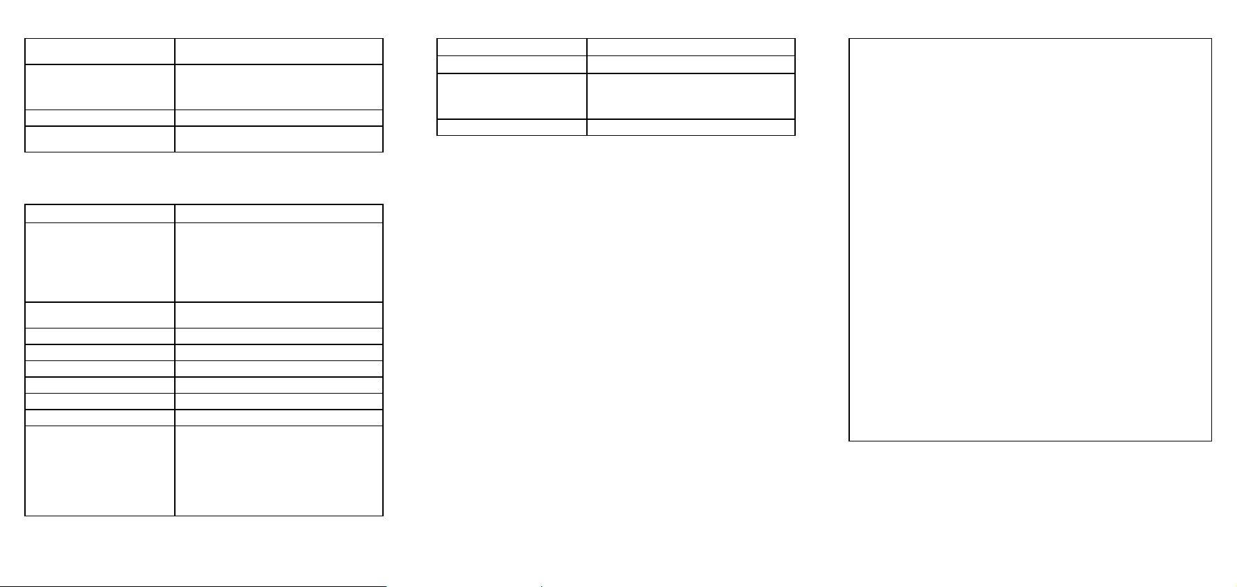
Safety Specifications
Maximum operating life 2 years after activation, assuming 3-5
minutes of alarm time/day
Detection range H2S: 0 to 100 ppm
CO: 0 to 300 ppm
O2: 0 to 30% by volume
SO2: 0 to 100 ppm
Alarm setpoints Instant low and instant high
Calibration H2S, CO, SO2: Not required
O2: Self-calibrating
Note: This product has been classified for use in atmospheres not more
than 21% v/v O2.
General Specifications
Shelf life 1 year before activation
Operating temperature
H2S: −40 to +122 oF / −40 to +50 oC
CO: −22 to +122 oF / −30 to +50 oC
SO2: −22 to +122 oF / −30 to +50 oC
O2: −4 to +122 oF / −20 to +50 oC
Internal vibrating option operates to: +5 oF /
−
15 oC
Operating humidity 5 % to 95 % relative humidity
(non-condensing)
Audible alarm ≈85 dB at 1 ft. (0.3 m)
Visual alarm Wide-angled alarm bar
Display Liquid crystal display (LCD)
Sensor type Electrochemical cells
Detection technique Instantaneous alarm
Battery Lithium, non-replaceable
Intrinsic safety Classified by UL to both U.S. and Canadian
Standards as intrinsically safe for Class I,
Division 1, Group A, B, C, D and Class I,
Zone 0, Group IIC
ATEX:CE 0539 gII 2 G DEMKO 02
ATEX 0235232
EX Approval: EEx ia IIC T5
CE: European Conformity
Data Event Specifications*
Number of stored events Up to 10 events encountered
Data transmission method Via infrared port to thermal printer
Information transmitted Gas type and alarm level in ppm or %
Duration of alarm in minutes and seconds
Time elapsed since the alarm occurred in
days, hours and minutes
Data transmission time 45 seconds plus 10 seconds per record
*EL models only.
Contacting BW Technologies
To contact BW Technologies call:
1-800-749-8878 USA 1-800-663-4164 Canada
+44 (0) 1869-233004 Europe +971-4-8871766 Middle East
+61-7-3818-8244 Australia +1-403-248-9226 other countries
Visit BW Technologies’ Web site at: www.gasmonitors.com
Corporate USA Europe
BW Technologies Ltd. BW Technologies Inc. BW Technologies Ltd.
2840 - 2 Avenue S.E. 3279 West Pioneer
Parkway 101 Heyford Park
Calgary AB Arlington TX Upper Heyford
Canada T2A 7X9 USA 76013 Oxfordshire
UK OX25 5HA
Warranty
LIMITED WARRANTY & LIMITATION OF LIABILITY
BW Technologies Ltd. (BW) warrants this product to be free from defects in material and
workmanship under normal use and service for a period of two years, beginning on the date
of shipment to the buyer. This warranty extends only to the sale of new and unused products
to the original buyer. BW’s warranty obligation is limited, at BW’s option, to refund of the
purchase price, repair, or replacement of a defective product that is returned to a BW
authorized service center within the warranty period. In no event shall BW’s liability hereunder
exceed the purchase price actually paid by the buyer for the Product.
This warranty does not include:
a) fuses, disposable batteries or the routine replacement of parts due to the normal wear
and tear of the product arising from use;
b) any product which in BW’s opinion, has been misused, altered, neglected or damaged
by accident or abnormal conditions of operation, handling or use;
c) any damage or defects attributable to repair of the product by any person other than an
authorized dealer, or the installation of unapproved parts on the product; or
The obligations set forth in this warranty are conditional on:
a) proper storage, installation, calibration, use, maintenance and compliance with the
product manual instructions and any other applicable recommendations of BW;
b) the buyer promptly notifying BW of any defect and, if required, promptly making the
product available for correction. No goods shall be returned to BW until receipt by the
buyer of shipping instructions from BW; and
c) the right of BW to require that the buyer provide proof of purchase such as the original
invoice, bill of sale or packing slip to establish that the product is within the warranty
period.
THE BUYER AGREES THAT THIS WARRANTY IS THE BUYER’S SOLE AND EXCLUSIVE
REMEDY AND IS IN LIEU OF ALL OTHER WARRANTIES, EXPRESS OR IMPLIED,
INCLUDING BUT NOT LIMITED TO ANY IMPLIED WARRANTY OF MERCHANTABILITY
OR FITNESS FOR A PARTICULAR PURPOSE. BW SHALL NOT BE LIABLE FOR ANY
SPECIAL, INDIRECT, INCIDENTAL OR CONSEQUENTIAL DAMAGES OR LOSSES,
INCLUDING LOSS OF DATA, WHETHER ARISING FROM BREACH OF WARRANTY OR
BASED ON CONTRACT, TORT OR RELIANCE OR ANY OTHER THEORY.
Since some countries or states do not allow limitation of the term of an implied warranty, or
exclusion or limitation of incidental or consequential damages, the limitations and exclusions
of this warranty may not apply to every buyer. If any provision of this warranty is held invalid
or unenforceable by a court of competent jurisdiction, such holding will not affect the validity
or enforceability of any other provision.

This manual suits for next models

8

Other BW Technologies Gas Detector manuals

BW Technologies GasAlert MicroClip XT User manual

BW Technologies

BW Technologies GasAlert MicroClip XT User manual

BW Technologies GasAlert Micro 5 User manual

BW Technologies

BW Technologies GasAlert Micro 5 User manual

BW Technologies GA24XT-H User manual

BW Technologies

BW Technologies GA24XT-H User manual

BW Technologies GasAlertMicro 5 User manual

BW Technologies

BW Technologies GasAlertMicro 5 User manual

BW Technologies GasAlertMicro 5 User manual

BW Technologies

BW Technologies GasAlertMicro 5 User manual

BW Technologies GasAlertMicroClip User manual

BW Technologies

BW Technologies GasAlertMicroClip User manual

BW Technologies GasAlert MicroClip XT User manual

BW Technologies

BW Technologies GasAlert MicroClip XT User manual

BW Technologies GasAlertClip Extreme User manual

BW Technologies

BW Technologies GasAlertClip Extreme User manual

BW Technologies GasAlertMicro 5 User manual

BW Technologies

BW Technologies GasAlertMicro 5 User manual

BW Technologies GasAlertMicro 5 User manual

BW Technologies

BW Technologies GasAlertMicro 5 User manual

BW Technologies GasAlertQuattro User manual

BW Technologies

BW Technologies GasAlertQuattro User manual

BW Technologies GasAlertQuattro 1 User manual

BW Technologies

BW Technologies GasAlertQuattro 1 User manual

Popular Gas Detector manuals by other brands

DEGA NS III LCD instruction manual

DEGA

DEGA NS III LCD instruction manual

Dräger Polytron FX operating manual

Dräger

Dräger Polytron FX operating manual

Teledyne GASURVEYOR 7B-500R User handbook

Teledyne

Teledyne GASURVEYOR 7B-500R User handbook

Hanwei BX176 Operation manual

Hanwei

Hanwei BX176 Operation manual

IMR EX610 user manual

IMR

IMR EX610 user manual

AKO AKO-522014 manual

AKO

AKO AKO-522014 manual

Sensitron HART manual

Sensitron

Sensitron HART manual

Axetris LGD F200P2 Operation and integration instructions

Axetris

Axetris LGD F200P2 Operation and integration instructions

Riken Keiki 70D Series Construction manual

Riken Keiki

Riken Keiki 70D Series Construction manual

Southern Cross Flame Pack 400 Series Operation and service manual

Southern Cross

Southern Cross Flame Pack 400 Series Operation and service manual

Medem SafeAir CM installation instructions

Medem

Medem SafeAir CM installation instructions

Evikon E2630-VOC user manual

Evikon

Evikon E2630-VOC user manual

Quest Technologies SafeLog 100 Operator's manual

Quest Technologies

Quest Technologies SafeLog 100 Operator's manual

AMS GASALARM S/200-P Installation and operating instructions

AMS

AMS GASALARM S/200-P Installation and operating instructions

GASTRON GTC-550 instruction manual

GASTRON

GASTRON GTC-550 instruction manual

Industrial Scientific OLDHAM 300 Series Operating and maintenance manual

Industrial Scientific

Industrial Scientific OLDHAM 300 Series Operating and maintenance manual

MSR Intec Controls PolyGard CO LC-1112 V3 user manual

MSR

MSR Intec Controls PolyGard CO LC-1112 V3 user manual

Helio SL Series operating manual

Helio

Helio SL Series operating manual

manuals.online logo
manuals.online logoBrands
  • About & Mission
  • Contact us
  • Privacy Policy
  • Terms and Conditions

Copyright 2025 Manuals.Online. All Rights Reserved.