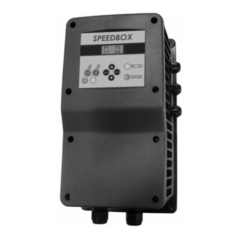
C.S.L. VARIVAC 2006 B User manual

1

2
Varivac™ Installation Manual
Contents
1. General Information
2. Varivac Mounting and wiring
3. Transducer Mounting and wiring
4. Set up and Automatic Motor Tuning
(AMA)
5. Vacuum Level Adjustment
6. Idle Speed Adjustment
7. Common Errors
8. Terms & Conditions
9. Internal wiring diagram
1. General Information
Varivac is a protected Trademark belonging to Corkill Systems Limited, unauthorised use
of this name will lead to prosecution.
Varivac is available in standard motor sizes from 4 kilowatts to 30 kilowatts, model
CSLV4 has a 4 kilowatt capacity, CSLV5.5 is 5.5 kilowatt, etc. The suffix “T” refers to a
Tandem Varivac, this model controls two motors simultaneously and has individual
motor circuit-breakers inside to protect the motors. The Varivac should be sized for the
combined rating of the motors, for example, 1 x 11kw + 1 x 7.5kw motor = 18.5kw,
therefore the model Varivac should be CSLV18.5T. Twin pump set ups are discouraged
where for example the larger vacuum pump is controlled by a Varivac and the second
pump is “called” as required. This system is cheaper to purchase but leads to problems as
the primary pump wears and the second pump is called more frequently causing a “blip”
in the vacuum as the pump comes in and is switched off again. Tandem pump systems
have been documented to be more economic to run even with two motors running plus
the total reserve in the combined motors is instantly available when required.
All enclosures are rugged Stainless Steel, be wary of mounting the Varivac in such a way
that the thermostatic controlled booster fan will not draw in moisture or steam when it

3
starts. Although all Varivacs have booster fans fitted, cooling is very rarely an issue and
covers are available to blank the fan off if moisture is the greater problem.

4
CABLING AND MOTOR
The Varivac is designed to be permanently wired on a dedicated circuit with protection
according to the controller Specification sheet current ratings. Cables to the electric
motor must be screened, minimum size 4 X 2.5mm, CBS type preferred. The Cable
between the Varivac and transducer is to be of minimum 0.2mm 2 core screened and not
to be run parallel with heavy current carrying cables. Belden type cable is preferred and is
supplied with the Varivac.
The power supply cable to the drive can be non screened TPS or similar
A Mains and RF filter is factory fitted internally in all controllers, this is normally
adequate however we recognize there are certain areas within NZ where this filter will
not be sufficient to suppress all radio interference, please contact us for more information
if this is the case.
In suspect poor power areas, should the incoming voltage drop below the unit tolerance
levels, the unit will trip on error 13. This requires a complete shut down and restart.
The client should talk to their electrician or network supplier if this condition persists as
the Electrical Regulations state minimum mains supply voltage levels. This requirement
is well above the controller Low Voltage tolerance level, please note that this low voltage
condition will not damage the controller but could damage other electrical apparatus.
The voltage tolerance level with three phase controllers is 380 volts.

5
2. Mounting and Wiring
Single Pump & Motor Combination
This system consists of one motor with one or more vacuum pumps attached.
1. Generally mount the Varivac adjacent the vacuum pump.
2. Re-use the existing isolator normally at this point.
3. Remove power factor capacitor if connected (Varivac does this function).
4. Remove motor cable from the motor and re-terminate into the Varivac supply
terminals L1, L2 & L3. Connect the Earth to the screw/terminal provided.
5. Fit a new cable (screened cable preferred) from the Varivac to the motor.
6. If the starter is at the switchboard, remove the overload and continue using this starter
to start the Varivac and any auxiliary equipment.
7. If the starter is adjacent the pump, remove completely and switch any Auxiliary
equipment via the relay provided in the Varivac (not more than 5 amps!)
8. If a Star/Delta Starter is being replaced, connect motor in Delta
– check the motor name plate for correct configuration!

6
Tandem Pump & Motor Combination
This system consist generally of two motors wired separately each with one or more
vacuum pumps attached. These motors may be of different sizes, this does not matter !
1. Generally mount the Varivac adjacent the switchboard.
2. Re-use the existing isolators normally by the motors.
3. Remove power factor capacitors if connected (Varivac does this function).
4. Connect a new cable from a circuit-breaker or fuses sized to handle the combined
vacuum pump motors full load current to the Varivac.
5. Either replace the motor cables with screened cables (this may not always be practical)
or re-route and connect the existing motor cables to the Motor Circuit-breakers in the
Varivac. Set the correct motor currents on the overloads in the Varivac enclosure.
6. If the starters at the switchboard are used to control auxiliary equipment, connect these
to the auxiliary relay in the Varivac, Terminals #6 & #7 – not more than 5 amps please !
7. If the starters are adjacent the pump, remove completely and connect to the isolators.
8. If Star/Delta Starters are being replaced, connect motors in 400 volt configuration,
Delta on 400/600v motors and Star on 230/400v motors – check the motor name plate.

7
Twin Pump & Motor Combination
This system is not normally used unless the plant has a huge vacuum over-capacity, it
consists generally of two motors wired separately each with one or more vacuum pumps
attached. These motors may be of different sizes, this does not matter!
1. Generally mount the Varivac adjacent the switchboard.
2. Re-use the existing isolators normally by the motors.
3. Remove power factor capacitors if connected (Varivac does this function).
4. The largest motor is connected via the Varivac.
5. Either replace the motor cable with screened cables (this may not always be practical)
or re-route and connect the existing motor cable to the Varivac.
6. If the starter at the switchboard is used to control auxiliary equipment, remove the
overload and use this contactor to start the Varivac, Terminals #6 & #7 in the Varivac
should be used to start the secondary pump contactor or soft starter (a soft starter is
highly recommended for this system).
7. If the starters are adjacent the pumps, mount the Varivac in the place of the largest
motor starter and connect the second starter to the Varivac.
8. If a Star/Delta Starter is being replaced, connect the motor in 400v configuration
– check the motor name plate!
9. A check valve will need to be fitted to the secondary pump inlet side to stop air being
pulled into the system via the vacuum pump exhaust when this pump is on standby.

8
3. Transducer Installation
General; mount the transducer as close to the action as possible, the sensing face is
VERY sensitive and easily damaged, be very careful with it.
Only mount the transducer in the Vacuum Interceptor when no other option is practical –
it will still work well but in high vacuum loss situations the vacuum at the cups will be
lower than at the transducer sensing face due to friction losses in the plant pipe work.
Herringbone Dairy – mount in the Hygienic Can as first choice or Milk Receiver as
second choice. The Hygienic can be drilled and a standard mounting kit used or insert in
the Milk Receiver, this will require the tri-clover fitting welded in (see photo) and creates
a point that must be cleaned periodically and therefore provides a risk of damaging the
transducer.

9
Rotary Dairy – mount as close as possible to the gland, in the installation photos below
the tee moves the transducer out of direct air flow – this is good. There is often a spare
outlet in the gland this is a good point to mount the transducer – beware of the transducer
being accidentally knocked by operators or moving pipe work. If possible always mount
the transducer upright to protect against moisture ingress.
Protect the transducer Belden cable through
the duct with conduit or flexi-conduit
vibration can crush the cable or rodents
may chew it
Connections:
Single pair screened belden cable is supplied with the Varivac, connect the white to
terminal #1 at both Transducer and Varivac and Black to terminal #2 with the drain wire
connected to Earth at both ends
Avoid running the transducer cable parallel with high current and/or voltage cables as
interference can be induced into the cable.

10
Do not mount the transducer ever like the following picture
This is Very Bad !!!! – all kinds of stability problems !!! – too close to the vacuum
pump and welded directly into a very small main air line.

11
4. Set Up and Automatic Motor Tuning
Programming To make program changes press “Menu” to start, make the changes and
press “Display” to end.
-
+
0.
Keyboard
& Display.
000
001
002
003
004
005
1. Load &
Motor
100
101
102
103
104
105
etc
2. Ref
& Limits
200
201
202
203
204
205
etc
3. Inputs &
Outputs
300
301
302
303
304
305
etc
4. Special
Functions
400
401
402
403
404
405
etc
5. Serial
Comms
500
501
502
503
504
505
etc
6. Tech
Functions
600
601
602
603
604
605
etc
Kwh
Hertz
Run
Kilowatts
Setup
Parameter Select
Parameter Data / Operational
Status
Access this entire line by pushing the
“Display” button
A constant number denotes the operating
setup selected, a flashing number shows the
setup being programmed
Normal Operation shows operation status,
When programming this line shows the
parameter data entry
Shows Kilowatts being used, can use the
“+” & “-“ keys to change
Only appears when programming,
shows the parameter # and
description
Use Sideways Keys to
move across the seven
Use “+” and “-” Keys to
move up and down the

12
1. After all connections are made, turn the “Test/Off/Auto” switch to “Off” and
power up the Varivac
2. Check Vacuum Pump Motor direction(s) by briefly turning the “Test/Off/Auto”
switch to “Auto” and then “Off” again. Turn the power completely off to the
Varivac to inter-change motor phases and change at the Varivac motor output
(singles) or the appropriate motor circuit breaker (Tandems). Re-power Varivac.
3.
4. Press the “Display” followed by the “Menu” button on the Danfoss Controller
Key-pad (LCP). The upper screen data line plus “0.Keyboard & Display” in the
lower screen should be showing plus a “1” at the right side of the screen. If a “3”
is showing at the right side, turn the “Milk/Wash” switch (or remote control of
this) to “Milk”- it should change back to Setup #1.
5. For Single Motor Installations only, press the right side arrow key once, “1. Load
& Motor” should be displayed. Repeat press the “+” key and check that the motor
name plate details are the same as you progress through from parameter #102 to
parameter #107. Change any details by pressing “Change Data” and then using
the “+” or “-“ keys. The curser can be moved by using the right and left arrow
keys. When the correct data is entered, press “OK” to save. At parameter #107,
press “Change Data” and select “ENABLE (RS,XS)” and press “OK”. Turn the
lid switch to “Auto”, the motor will not start and noises will be heard as the
controller tunes to the motor – this takes about 5 minutes. Alarm 21 will be
displayed when the tuning is complete. Turn Off the lid switch before pressing
“Stop/Reset” on the LCP or else the motor will start!
6. Step 4 is NOT to be carried out for Tandem Varivacs.
7. The Varivac is ready to operate.

13
5. Vacuum Level Adjustment
Setting the air regulator or air regulators.
There are two types of air regulators remote sensing and standard types, remote sensing
types have a long pipe attached to the air regulator and attached to the sensor within the
air line or close to the gland in rotary sheds. All air regulators have and adjustment screw
in them that is used to set the vacuum in the plant, most remote types have the adjustment
at the sensor. Partial disassembly of some types are necessary, but usually are contained
within a rubber or plastic cap on the top or side usually in the center of the device and
quite often contain a locking nut or screw to stop vibration altering the device.
Firstly now that the varivac is all set up to run you must first check the existing vacuum
level on the gauge within the shed and note this down, do this running the varivac in
“TEST” mode and getting the plant up to vacuum.
After you have found the adjustment screw for the air regulator you can adjust the air
regulator or air regulators one at a time by unscrewing one at time and blocking off the
hole with something and turning the screw until the vacuum is set between four and six
kpa above the vacuum level as noted before.
Adjusting the milking and wash vacuum level.
Switch the Varivac into the “AUTO” letting it ramp up to speed making sure the plant is
up to vacuum.
Release the lock on the vacuum ten turn adjustment potentiometer labeled “MILK” and
wind SLOWLY clockwise for higher vacuum and anti-clockwise for lower vacuum. On
Water Ring vacuum pumps this adjustment should be carried out with one cluster
open. While at idle the vacuum level in a dairy with a Water Ring vacuum pump will be
just above the operational setting, the higher parameter #201 is above the seal collapse
point, the higher this idle point will be. As soon as the first cluster is opened, the vacuum
will immediately move to the set point and stay there until the maximum pump speed is
reached. On systems with the transducer a long way from the sensing point, the vacuum
set point may vary according to the friction losses in the vacuum line by up to 1 Kpa.
This can only be rectified by moving the transducer closer to the incoming air point.
Make sure that the potentiometer is relocked after adjustments have been made.
The same procedure can now be carried out in “Wash” mode. In general use a higher
setting to achieve a hotter wash (water boils at lower temperature) or a lower setting if the
milk pumps struggle to remove the wash water (they will be more efficient at a lower
vacuum level). The VARIVAC reacts more slowly to vacuum requirements in “Wash”
than in the “Milk” position. Washing the plant in “Milk” mode with an Air Injector
operating may cause the controller to overload due to the fast response times to the
frequent high volumes of air being admitted to the vacuum system. When the settings are
optimum, write the potentiometer settings inside the lid with a marker pen for future
reference.

14
Try opening clusters until the controller is unable to hold the vacuum level, close again
quickly to test whether the original Air Regulator(s) will pull in, if they do, adjust the
regulator in “Test” to a higher level.
When the pump has reached maximum speed (pre programmed to 55Hz) with a number
of clusters open, verify the kilowatt draw shown on the display against the name plate
data. Parameter #202 can be moved up or down to set the kilowatts at approximately 15%
higher than the nameplate data. This will give the plant a greater vacuum reserve.
Warning; long periods with the pump at maximum speed will cause overloading and a
higher power usage. A balance between extra vacuum reserve and power saving should
be according to the farmers wishes.
Turn the “Auto/Off/Test” switch to off. Allow the pump to stop. Turn the switch to
“Test”, the controller will start and run at 50Hz constant and the air regulators will come
in. This is a “Manual” operation mode which can be used by machine fitters to establish
vacuum reserve in the conventional mode. Remember that the “Auto” mode will give an
additional approximately 15% reserve depending on parameter #205 setting and
pump/motor/plant size, in Setup 1. Setup 2 will come in automatically after 60 seconds
and reduce loading to the rated motor load until overload situation has been rectified. It
will then revert back to Setup 1.

15
6 Idle Speed adjustment
Water Ring Vacuum Pumps.
Start up the varivac in “AUTO” and get the plant up to vacuum with the selector in
“Milk” and then open one cluster.
Close the cluster and listen to the pump, the vacuum level may rise slightly at this point,
this is normal. If the pump hunts, go to parameter #203 and raise the setting until the
pump just stops hunting (the water ring is collapsing causing this effect).
If the pump does not hunt but the vacuum rises significantly, lower this setting to just
above the seal collapse position. This setting will need to be changed for “wash” also.
If the system is a two pump & motor set up (twin), this setting will also need to be
changed in Setup #2 PLUS parameter #225 will need setting at 2.5Hz above this setting.
Maximum speed is set at 55 Hz; by opening clusters until the top speed is reached (this
can be seen on the top of the screen by pressing the “Display” button). The speed can be
raised until the kilowatt reading is approximately 15% above the nameplate rating. If
doing this with a two pump & motor set up, parameter #226 in Setup #1 will need to be
set to 2.5Hz below the new maximum setting.
Blower and Oil vane Vacuum Pumps.
Start up the varivac in “AUTO” and get the plant up to vacuum with the selector in
“Milk” the vacuum level may rise slightly at this point if so lower the minimum speed of
the pump using parameter #201 to return to the normal milking level normal milking
level parameter #439 will have. This setting will need to be changed for “wash” also.
If the vacuum seems to be about right when it is running in auto adjust
If the system is a two pump & motor set up (twin), this setting will also need to be
changed in Setup #2 PLUS parameter #225 will need setting at 2.5Hz above this setting.
Maximum speed is set at 55 Hz, by opening clusters until the top speed is reached (this
can be seen on the top of the screen by pressing the “Display” button). The speed can be
raised until the kilowatt reading is approximately 15% above the nameplate rating. If
doing this with a two pump & motor set up, parameter #226 in Setup #1 will need to be
set to 2.5Hz below the new maximum setting.
High speed or high performance types of vacuum pumps may clatter when running at low
speeds when all of the clusters are closed off this is normal and will go away when the
cups are placed on the cows.
This is caused by the vanes of the pump dropping as there is not enough centrifugal force
to spin them out this happens because the pump has such a huge vacuum over capacity in
the plant (over spec pump for plant). This can be over come by increasing the minimum
speed of the pump such that it minimizes the clatter and doesn’t increase the vacuum too
much at idle.

16
Maximum speed is set at 55 Hz, by opening clusters until the top speed is reached (this
can be seen on the top of the screen by pressing the “Display” button). The speed can be
raised until the kilowatt reading is approximately 15% above the nameplate rating. If
doing this with a two pump & motor set up, parameter #226 in Setup #1 will need to be
set to 2.5Hz below the new maximum setting

17
7 Trouble Shooting
RUNNING FIRST TIME FAULTS Drive won’t start.
Remote start not wired properly, drive in local stop after performing ama, overloads
tripped (tandem models only).
Cause/Remedy: check to see if overloads tripped (tandem models only) reset if necessary
and set them to the correct current rating for the motors.
Check to see if remote start is wired correctly by placing a wire link between terminal 3
and 4 of the remote start terminals.
After doing an ama you will need to reset the drive it may show local stop on the display
you will need to press “RESET” and then “START” on the control panel on the Danfoss
Drive.
RUNNING FIRST TIME FAULTS Drive won’t speed up in auto
Drive pots are set incorrectly, Break in transducer cabling or transducer wired incorrectly
into Varivac
Cause/Remedy: check to see if Varivac is working by temporally shorting terminals 1
and 2 by placing long nose pliers into the terminals drive should speed up indicating that
there is a fault with the pot adjustment or transducer.
In the main display use the up or down button to check the transducer current on terminal
60, if the current is 0 then there is a fault with the transducer cabling or the wiring of the
transducer wiring it’s self.
If the current is above 4ma then the pots for vacuum adjustment simply need adjusting to
the correct vacuum level in the plant.
RUNNING FIRST TIME FAULTS Drive won’t slow down in auto
Short in transducer cabling, forced into setup four, air regulator set to close to varivac,
plant not gaining vacuum
Cause/Remedy: check that the plant is up to vacuum and check the vacuum level, check
that the drive is in the correct setup 1, 2 or 3.
If drive is in auto but showing setup 4 then the setup is forced and you need to go into
parameter 4 and select multi setup.
In the main display use the up or down button to check the transducer current on
terminal 60, if the current is 20ma then there is a fault with the transducer cabling or the
wiring of the transducer wiring it’s self.
RUNNING FIRST TIME FAULTS Drive won’t switch setups or runs at 50 Hz in
auto or is controlled in test. Drive is forced into a setup.

18
Cause/Remedy: check that drive is switching setups by switching the milk wash switch
when in auto.
If drive is not switching setups need to go into parameter 4 and select multi setup.
Common Error Messages.
WARNING/ALARM 4 Phase fault (MAIN PHASE LOSS).
A phase is missing on the supply side or the mains voltage imbalance is too high.
This message can also appear if there is a fault in the input rectifier on the frequency
converter.
Cause/Remedy: Check to make sure all 3 Phases are ok to the Varivac, if these are ok
check other 3 Phase equipment in the Dairy. E.g. to make sure your power supply is ok
to the Dairy. Turn off the Varivac completely for 40 sec then back on, “RESET” and
then “START” may need to be pressed on the control panel on the Danfoss Drive.
WARNING 6 Voltage warning low (DC LINK VOLTAGE LOW).
The intermediate circuit voltage (DC) is below the under voltage limit of the control
system.
Cause/Remedy: The incoming voltage to the Varivac is too low for it to operate.
E.g. there could be a fault with the power lines. The voltage will need to be returned to
normal for the Varivac to operate
WARNING/ALARM 9 Inverter Overload (INVERTER TIME).
The electronic, thermal inverter protection reports that the frequency converter is about to
cut out because of an overload (too high current for too long). The counter for electronic,
thermal inverter protection gives a warning at 98% and trips at 100%, while giving an
alarm. The frequency converter cannot be reset until the counter is below 90%.
The fault is that the frequency converter is overloaded by more than 100% for too
long.
Cause/Remedy: Too many cups open for too long, too many ramps in “Milk” when the
Varivac should be in “Wash”. Excessive air emissions, incorrect motor data has been put
into the drive. Turn off the Varivac completely for 40 sec then back on, “RESET” and
then “START” may need to be pressed on the control panel on the Danfoss Drive.
WARNING/ALARM 13 Over current (OVERCURRENT).
The inverter peak current limit (approx. 200% of the rated current) has been exceeded.
The warning will last approx 1 – 2 seconds, following which the frequency converter will
trip, while giving an alarm. Turn off the frequency converter and check whether the
motor shaft can be turned and whether the motor size matches the frequency converter. If
extended mechanical brake control is selected, trip can be reset externally.
Cause/Remedy: Too many cups open for too long, excessive air emissions, incorrect
motor data has been put into the drive. Turn off the Varivac completely for 40 sec then

19
back on, “RESET” and then “START” may need to be pressed on the control panel on
the Danfoss Drive.
ALARM 14 Earth fault (EARTH FAULT).
There is a discharge from the output phases to earth, either in the cable between the
frequency converter and the motor or in the motor itself. Make sure no power factor
capacitor is fitted to the motor.
Cause/Remedy: Either the motor or the cable to the motor has a short to earth in it.
An Electrician will have to check this.
Turn off the Varivac completely for 40 sec then back on, “RESET” and then “START”
may need to be pressed on the control panel on the Danfoss Drive.
ALARM 16 Short-circuit (CURR.SHORT CIRCUIT):
There is a short circuit on the drive output, this could be in the cable, isolator or motor
terminals or windings.
Cause/Remedy: Either the motor or the cable to the motor has a short to earth in it.
An Electrician will have to check this.
Disconnect the drive at the motor output terminals and turn the Varivac back on to prove
the controller is OK.
Turn off the Varivac completely for 40 sec then back on, “RESET” and then “START”
may need to be pressed on the control panel on the Danfoss Drive.

20
Corkill Systems Limited - TERMS AND CONDITIONS OF SALE
GENERAL
All quotations, orders and contracts for the sale or supply of goods or services by Corkill Systems Limited shall unless, otherwise agreed in writing,
be subject to the following terms and conditions:
1. ORDERS
All orders are made and accepted on the terms and conditions here stated. Order cancellations are subject to terms agreed as at time of
cancellation.
2. PRICES Prices quoted remain firm for 30 days but beyond that time prices may be adjusted.
3. DELIVERY
Delivery dates given by Corkill Systems Limited are approximate and rely on prompt receipt of all necessary information regarding the
order. Corkill Systems Limited will use their best effort to meet the estimated date but will not be held liable for any delay due to
circumstances arising in the industry generally or within Corkill Systems Limited work due to delay in receipt of supplies from sub-
contractor or any other circumstances beyond Corkill Systems Limited control. No liability will be taken for any late deliveries unless
delivery date has been guaranteed by Corkill Systems Limited in writing. Otherwise Corkill Systems Limited will use its best endeavour
to meet delivery dates.
4. DELIVERY CHARGES
Unless otherwise agreed in writing or at the discretion of Corkill Systems Limited, all freight will be charged to the Purchaser’s account.
5. RETURN OF GOODS
No goods may be returned without prior written approval of Corkill Systems Limited and may be subject to a restocking fee. Approval
will be contemplated by Corkill Systems Limited only in circumstances where:
5.1 Advice of any proposed return is given within 30 days following the date of the invoice.
5.2 Transportation and other costs for return are prepaid by the Purchaser
5.3 Goods to be accompanied by a copy of Corkill Systems Limited Packing Slip or Invoice
5.4 Goods to be accompanied by a written explanation of reasons for return.
5.5 Corkill Systems Limited may charge for handling, inspection, disassembly or reconditioning stock items.
5.6 Units manufactured, modified or imported as special or unique units will only be accepted for credit
less the cost of converting the unit back to a standard saleable unit.
6. TERMS OF PAYMENT
All goods shall be paid for on the 20th day of the month following delivery. Corkill Systems Limited may at any time require full or part
payment in advance of delivery and the purchaser shall not be entitled to any damages or compensation arising from such requirement.
Goods on time payment shall be subject to the conditions on the Time Payment contract in addition to the terms contained within this
document.
7. PRODUCT SAFETY
Corkill Systems Limited products are supplied and manufactured to high standards but no electrical equipment is failsafe within itself.
When risk to person or property may be involved a fail-safe device should be an integral part of the equipment, the entire responsibility
for which rests with the Purchaser.
8. OWNERSHIP OF GOODS
The goods shall remain the property of Corkill Systems Limited until they have been fully paid for. Risk shall pass to the purchaser on
delivery. The purchaser will insure the goods. The purchaser acknowledges that it is in possession as agent and bailee for Corkill
Systems Limited and owes a fiduciary duty to Corkill Systems Limited until such time as legal and equitable title shall transfer. The
purchaser’s right to possession of unpaid goods shall terminate on demand by Corkill Systems Limited, which may enter or authorise an
agent to enter the purchaser’s premises to recover the goods.
9. PRODUCT WARRANTY
Provided that the product has been subjected to normal and proper use only, all new products supplied by the company are warranted
to be free from defects in materials and workmanship from the date of shipment to the Purchaser either for one year or the
Manufacturers warranty term subject to the following conditions:
10.1 All electrical equipment to be installed and commissioned by qualified trade-persons.
10.2 Adequate measures to be taken against moisture and/or mechanical damage.
10.3 Recommended cabling procedures and/or circuitry protection must be provided.
10.4 Suitable overload protection be provided and installed where required.
10.5 All faulty components to be returned to Corkill Systems Limited before a credit can be made.
In the event of equipment failure, all faulty components will be repaired or replaced free of charge, consequential loss/equipment
damage and/or labour and/or travelling will not be subsidised. Any unauthorised dismantling, repair or modification voids this warranty.
10. LIABILITY UNDER WARRANTY
Corkill Systems Limited liability under this warranty or any other warranty whether express or implied in law or fact shall be limited to the
repair or replacement of defective material and workmanship and in no event shall Corkill Systems Limited be liable for consequential or
indirect damages.
11. GOVERNING LAW This agreement shall be construed according to the laws of New Zealand.
This manual suits for next models
1
Popular Control System manuals by other brands
Anticimex
Anticimex Smart Connect Mini user manual
Johnson Controls
Johnson Controls FC-2000 introduction

CIAT
CIAT AQUACIATPOWER LD-ST Series instruction manual
CNC Design
CNC Design CNC GUITAR PICKUP QUAD COIL WINDER MK1 instructions
Roger
Roger MCT88M-IO installation manual

Toshiba
Toshiba JOKC1 instruction manual
