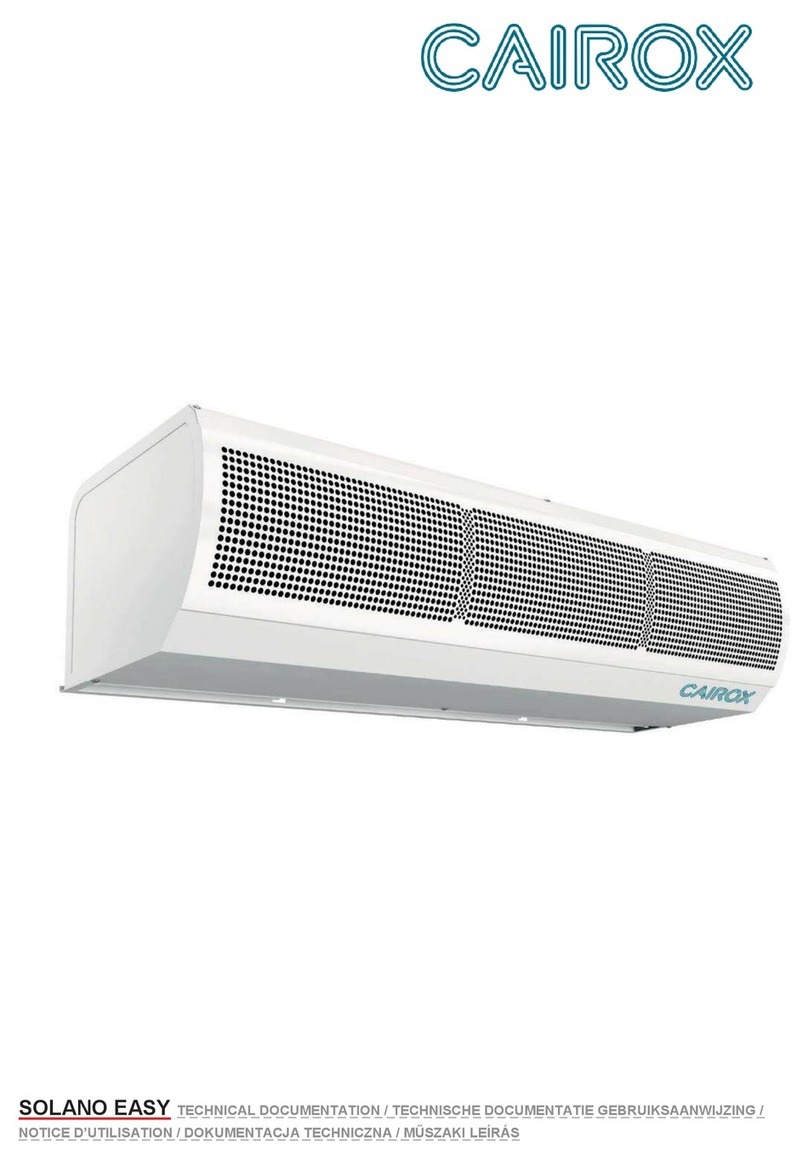
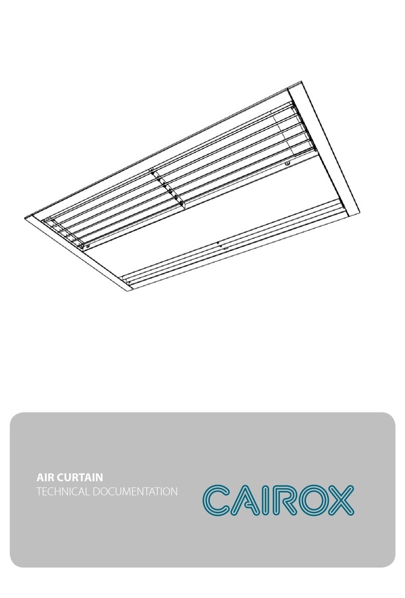
Cairox SOLANO EASY Guide

AIR CURTAIN
TECHNICAL DOCUMENTATION
------------------------------------------------
LUCHTGORDIJN
TECHNISCHE DOCUMENTATIE
GEBRUIKSAANWIJZING
------------------------------------------------
RIDEAU D’AIR
NOTICE D’UTILISATION
------------------------------------------------
KURTYNA POWIETRZNA
DOKUMENTACJA TECHNICZNA
------------------------------------------------
LÉGFÜGGÖNY
MŰSZAKI LEÍRÁS

1. GENERAL INFORMATION.....................................................................................................................................................2
2. APPLICATION. ........................................................................................................................................................................2
3. DIMENSIONS...........................................................................................................................................................................3
4. TECHNICAL DATA.................................................................................................................................................................4
5. INSTALLATION.......................................................................................................................................................................4
6. ASSEMBLY INSTRUCTIONS .................................................................................................................................................5
7. UNDER CEILING MOUNTED.................................................................................................................................................6
8. CONNECTING..........................................................................................................................................................................6
8.1. CONNECTION DIAGRAM SOLANO EASY-W ...................................................................................................................7
8.2. CONNECTION DIAGRAM EASY-E .....................................................................................................................................8
8.3. REGULATION S-TOUCH - SOLANO EASY W/N WIRING DIAGRAMS .........................................................................9
8.4. REGULATION S-TOUCH - SOLANO EASY E WIRING DIAGRAMS .............................................................................10
9. START UP AND OPERATION ...............................................................................................................................................11
10. HEATING CAPACITY ..........................................................................................................................................................52
The SOLANO EASY device group includes the following models:
EASY-W-100 –curtain with water heat exchanger,
EASY-W-150 –curtain with water heat exchanger,
EASY-W-200 –curtain with water heat exchanger,
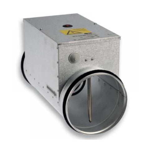
EASY-E-100 –curtain with electrical heat exchanger,
EASY-E-150 –curtain with electrical heat exchanger,
EASY-E-200 –curtain with electrical heat exchanger.
EASY-W/E (100/150/200) –air curtains in standard version with 3-gear fan and mounting plate.
Thank you for purchasing the SOLANO EASY air curtain.
The manufacturer reserves the right to make revisions and changes in the operation manual at any time and
without notice,and also to make changes in the device that do not influence its operation. This manual is an
integral part of the device and it must be delivered to the user together with the device. In order to ensure
correct operation of the equipment, get thoroughly acquainted with this manual and keep it for the future.
Air Curtain SOLANO BASIC is to be installed over the door opening, it provides dynamic barrier against
external factors. The devices are designed for indoor use where maximum air dustiness does not exceed
0,3 g/m3. Units are built using copper, aluminum and galvanized steel. It is prohibited to install units in the
areas where environment inside can cause corosion.


EASY-E-100
EASY-E-150
EASY-E-200
Step
1
2
3
1
2
3
1
2
3
Air flow [m3/h]
900
1100
1300
1450
1650
1950
2100
2300
2700
Puissance [kW]
6,5
10
13
Temp. increase [°C]
15
15
15
Power supply [V/Hz]
3x400/50
3x400/50
3x400/50
Max current consumption [A]
9,4
14,5
18,7
IP/Insulation class
21 /F
21 /F
21 /F
Max acoustic pressure level [dB(A)]**
44,5
46,5
48,5
46,5
48,5
50,5
48,5
50,5
52,5
Range [m]
3
3
3
Max working temperature [°C]
60
60
60
Device mass[kg]
14,5
19,9
25,1
* Temperature increase at inlet air 10oC and heating agent temperature 90/70oC
** Acoustic pressure level has been measured 3 m from the unit in a 500 m3space with a medium sound absorption coefficient
EASY-W-100
EASY-W-150
EASY-W-200
Step
1
2
3
1
2
3
1
2
3
Air flow [m3/h]
1050
1250
1400
1600
1850
2100
2300
2600
3000
Heating Capacity [kW]*
14,9
22,8
32,5
Temp. increase [°C]
31
32
32
Power supply [V/Hz]
230/50
230/50
230/50
Max current consumption [A]
0,65
0,95
1,2
Max power consumption [W]
140
210
260
IP/Insulation class
21 /F
21 /F
21 /F
Max acoustic pressure level [dB(A)]**
44,5
46,5
48,5
46,5
48,5
50,5
48,5
50,5
52,5
Max heating water temperature [°C]
90
90
90
Max operating pressure [MPa]
1,2
1,2
1,2
Internal thread connection
¾”
¾”
¾”
Range [m]
3
3
3
Max working temperature [°C]
60
60
60
Device mass[kg]
19
27,5
35,1
Air curtains can be mounted horizontal. During the montage, the
minimal distances from the walls and ceiling have to be kept.

1. Unscrew the screws from mounting bracket.
3. Put the curtain on the bracket.
2. Bracket should be mounted to the wall with 4 screws M8.
Hole spacing:
EASY-W/E-100 90x440 mm
EASY-W/E-150/200 90x840 mm
4. After installing the unit on the bracket, tighten
the screws (point 1) then put the plastic cover on
screw hole.

4 pcs. of pins M8 should be screwed into the curtain min. at a length of 20 mm
Model
AxB [mm]
EASY-W-100
181x948
EASY -W-150
181x1448
EASY -W-200
181x1958
EASY -E-100
80x948
EASY -E-150
80x1448
EASY -E-200
80x1958
To connect the control system and power supply to the SOLANO EASY curtain, remove the cover (unscrew 2 screws) located
at the top of the unit.
GUIDE
MOUNTED

❶Power supply 230V/50Hz (OMY 3x1,0mm2)
❷Air curtain step switch with thermostat S-C (OMY 5x0,5mm2)
FAN AUTO –fan operating depending on room thermostat signal
FAN CONT –fan operating continuously (deactivated thermostat signal)
HEAT –heating mode
FAN –room thermostat deactivated for FAN CONT
COOL –cooling mode
❸Door switch S-DS-RMAG/S-DS-MEC (OMY 2x0,5mm2) (door opened –closed switch)
❹Valve with actuator S-V-3-3/4 (OMY 3x0,75mm2) / S-V-2-3/4 (OMY 3x0,75mm2)
A –Exchanger water supply
AB –Valve water supply
B –Return pipe water supply
2

8
❶Power supply 3x400V/50Hz
EASY-E-100 (5x2,5 mm2); Overcurrent breaker B16
EASY-E-150 (5x2,5 mm2); Overcurrent breaker B20
EASY-E-200 (5x4,0 mm2); Overcurrent breaker B25
❷Air curtain step switch with thermostat S-C (OMY 7x0,5mm2)
FAN AUTO* –fan operating depending on room thermostat signal
FAN CONT –fan operating continuously (deactivated thermostat signal)
HEAT –heating mode
FAN –room thermostat deactivated for FAN CONT
COOL –cooling mode
❸Door switch S-DS-RMAG/S-DS-MEC (OMY 2x0,5mm2) (door opened –closed switch)
*To set AUTO MODE, it is required to connect the cable with connectors 3 and 4 in the curtain parallel to the
connector 3 in the controller S-C

❶Power supply 230V/50Hz (OMY 3x1mm2)
❷S-TOUCH (OMY 4x0,5mm2)
❸Door contact S-DS.
S-DS. MAG / S-DS-MEC (door closed –contacts opened;
door opened contacts closed) (OMY 2x0,5mm2)
Valve with actuator S V-2 (OMY 3x0,75mm2) or
S-V-3 (OMY 3x0,75mm2)
A –Exchanger water supply
AB –Valve water supply
B –Return pipe water supply
NOTE: In last DRV in line, dipswitch SW2 has to be switched to the right –T120.

10
❶Power supply 3x400V/50Hz
• EASY-E-100 (min. 5x2,5 mm2) (Overcurrent B16)
• EASY-E-150 (min. 5x4,0 mm2) (Overcurrent B20)
• EASY-E-200 (min. 5x4,0 mm2) (Overcurrent B25)
❷S-TOUCH (OMY 4x0,5mm2)
❸Door contact S-DS. MAG / S-DS-MEC (door closed –contacts opened; door opened –contacts closed) (OMY
2x0,5mm2)
ATTENTION:
Switch 4 on SW3 to the position “E” and then restart the system switching it off for 5 seconds. Each time the device
is switched off the heaters are being cooled for next 30 seconds

GUIDELINES FOR SYSTEM CONNECTION
• The connection should be executed in a way which does not induce stresses. It is recommended to use flex pipes
to connect the stubs.
• It is recommended to install vent valves at the highest point of the system.
• The system should be executed so that, in the case of a failure, it is possible to disassemble the device. For this
purpose it is best to use shut-off valves just by the device.
• The system with the heating medium must be protected against an increase of the heating medium pressure above
the permissible value (1.2 MPa).
• While screwing exchanger to pipeline - connecting stubs has to be hold by wrench.
START UP
• Before connecting the power supply check the correctness of connection of the fan motor and the controllers.
These connections should be executed in accordance with their technical documentation.
• Before connecting the power supply check whether the mains voltage is in accordance with the voltage on the
device data plate.
• Before starting the device check the correctness of connection of the heating medium conduits and the tightness
of the system.
• Starting the device without connecting the ground conductor is forbidden.
OPERATION
• The device is designed for operation inside buildings, at temperatures above 0oC. In low temperatures
(below 0oC) there is a danger of freezing of the medium. The manufacturer bears no responsibility for damage
of the heat exchanger resulting from freezing of the medium in the exchanger. If operation of the device is
expected at temperatures lower than 0o, then glycol solution should be used as the heating medium, or special
automatic systems should be used for protecting against freezing of the medium in the exchanger.
• It is forbidden to place any objects on the heater or to hang any objects on the connecting stubs.
• The device must be inspected periodically. In the case of incorrect operation of the device it should be switched
off immediately. It is forbidden to use a damaged device. The manufacturer bears no responsibility for damage
resulting from the use of a damaged device.
• If it is necessary to clean the exchanger, be careful not to damage the aluminium lamellas.
• For the time of performing inspection or cleaning the device, the electrical power supply should be disconnected.
• In case water is drained from the device for a longer period of time, the exchanger tubes should be emptied
withcompressed air.
• § It is not allowed to make any modification in the unit. Any modification causes in warranty loss.

12
1. ALGEMENE INFORMATIE...................................................................................................................................................12
2. TOEPASSING. ........................................................................................................................................................................12
3. AFMETINGEN........................................................................................................................................................................13
4. TECHNISCHE GEGEVENS ...................................................................................................................................................14
5. INSTALLATION.....................................................................................................................................................................14
6. MONTAGE INSTRUCTIES....................................................................................................................................................15
7. AANSLUITINSTRUCTIE.......................................................................................................................................................16
8. PLAFONDMONTAGE............................................................................................................................................................16
8.1. AANSLUITSCHEMA SOLANO EASY-W .........................................................................................................................17
8.2. AANSLUITSCHEMA EASY-E............................................................................................................................................18
8.3. REGELING S-TOUCH - SOLANO EASY W/N ELEKTRISCHE SCHEMA'S..................................................................19
8.4. REGELING S-TOUCH - SOLANO EASY ELEKTRISCHE SCHEMA'S ..........................................................................20
9. IN BEDRIJF STELLEN EN WERKING .................................................................................................................................21
10. VERWARMINGSCAPACITEIT...........................................................................................................................................52
The SOLANO EASY serie omvat de volgende uitvoeringen:
EASY-W-100 –luchtgordijn met waterwarmtewisselaar,
EASY-W-150 –luchtgordijn met waterwarmtewisselaar,
EASY-W-200 –luchtgordijn met waterwarmtewisselaar,
EASY-E-100 –luchtgordijn met elektrische verwarmingselementen,
EASY-E-150 –luchtgordijn met elektrische verwarmingselementen,
EASY-E-200 –luchtgordijn met elektrische verwarmingselementen,
EASY-W/E (100/150/200) –luchtgordijnen SOLANO EASY worden standaard geleverd met S-C thermostaat
3- standenregeling en wandmontagebeugel.
Hartelijk dank voor uw keuze voor het SOLANO EASY C-luchtgordijn.
De fabrikant behoudt zich het recht voor om te allen tijde zonder voor-afgaande kennisgeving revisies en wij-zigingen in de
gebruiksaanwijzing aan te brengen en ook modificaties aan het apparaat aan te brengen die de werking ervan niet
beïnvloeden.
Deze gebruiksaanwijzing is een integraal onderdeel van het apparaat en het moet bij het apparaat aan de gebruiker worden
mee-geleverd. Lees voor een correcte werking van het apparaat deze gebruiksaanwijzing grondig door en bewaar de
gebruiksaanwijzing zodat u deze in de toekomst nogmaals kunt nalezen.
Het luchtgordijn SOLANO EASY moet worden gemonteerd boven de deuropening als een dynamische barrière tegen
externe factoren. De units zijn ontworpen voor binnengebruik in een omgeving met een stofbelasting lager dan 0,3 g/m3
. In
de units is koper, aluminium en gegalvaniseerd staal gebruikt. Het is niet toegestaan om units te monteren in een omgeving
die roestvorming in het inwendige van de units kan veroorzaken.


EASY-E-100
EASY-E-150
EASY-E-200
Stand
1
2
3
1
2
3
1
2
3
Max. luchthoeveelheid [m3/uur]
900
1100
1300
1450
1650
1950
2100
2300
2700
Energieverbruik [kW]
6,5
10
13
Temperatuurstijging [ °C]
15
15
15
Stroomvoorziening [V/Hz]
3x400/50
3x400/50
3x400/50
Max. stroomverbruik [A]
9,4
14,5
18,7
IP/Isolatieklasse
21 /F
21 /F
21 /F
Max. akoestisch drukniveau [dB(A)]**
44,5
46,5
48,5
46,5
48,5
50,5
48,5
50,5
52,5
Bereik [m]
3
3
3
Max. temperatuurstijging [°C] |
60
60
60
Gewicht van de unit [kg]
14,5
19,9
25,1
* Temperatuurstijging bij inlaatluchttemperatuur van 10 °C en temperatuur van het verwarmingsmedium van 90/70 °C
** Akoestisch drukniveau in een ruimte met een gemiddelde geluidsabsorptie, inhoud ruimte >500 m32e ventilatiestand,
gemeten op 3m afstand van de unit.
EASY-W-100
EASY-W-150
EASY-W-200
Stand
1
2
3
1
2
3
1
2
3
Max. luchthoeveelheid [m3/uur]
1050
1250
1400
1600
1850
2100
2300
2600
3000
Verwarmingscapaciteit [kW]*
14,9
22,8
32,5
Temperatuurstijging [ °C]
31
32
32
Stroomvoorziening [V/Hz]
230/50
230/50
230/50
Max. stroomverbruik [A]
0,65
0,95
1,2
Max. energieverbruik [W]
140
210
260
IP/Isolatieklasse
21 /F
21 /F
21 /F
Max. akoestisch drukniveau [dB(A)]**
44,5
46,5
48,5
46,5
48,5
50,5
48,5
50,5
52,5
Max. watertemperatuur
verwarming [°C]
90
90
90
Max. bedrijfsdruk [MPa]
1,2
1,2
1,2
Aansluiting met binnendraad
¾”
¾”
¾”
Bereik [m]
3
3
3
Max. temperatuurstijging [°C]
60
60
60
Gewicht van de unit [kg]
19
27,5
35,1
Luchtgordijnen kunnen horizontaal worden
gemonteerd. Bij het monteren moet de minimale
afstand tot muren en plafons worden aangehouden.
.

1. Draai de schroeven van de montagebeugel los.
3. Plaats de unit op de beugel.
2. Monteer de beugel op de wand met 4
schroeven M8.
Hartafstand gaten:
EASY-W/E-100 90x440 mm
EASY-W/E-150/200 90x840 mm
4. Draai de schroeven (1) vast nadat de unit op de beugel is
geplaatst en plaats een plastic dopje over de schroefkop.

Schroef 4 st. M8-draadstangen minimaal 20 mm in de unit.
Model
AxB [mm]
EASY-W-100
181x948
EASY -W-150
181x1448
EASY -W-200
181x1958
EASY -E-100
80x948
EASY -E-150
80x1448
EASY -E-200
80x1958
Draai de schroeven van de kap aan de bovenkant van de unit los en verwijder de kap om het regelsysteem en de voeding van
het SOLANO EASY luchtgordijn aan te sluiten.
MOUNTED

❶Stroomvoorziening: 230 V/50 Hz (3-aderig, min 3 x 1,0 mm2)
❷Luchtgordijn te bedienen met S-C thermostaat 3 standenregeling
S-C (OMY 5x0,5 mm2).
FAN AUTO –Werking van de ventilator wordt geregeld door het signaal van de S-C ruimtethermostaat
FAN CONT –Ventilator is continu ingeschakeld (signaal van de thermostaat gedeactiveerd)
HEAT –Verwarmingsstand
FAN –Ruimtethermostaat gedeactiveerd. Enkel ventilatie. Geen verwarming.
COOL –Koelingsstand
❸Deurschakelaar S-DS-RMAG/S-DS-MEC (OMY 2x0,5mm2), (Schakelaar deur open –gesloten).
❹(OMY 3x0,5mm2) / S-V-2-3/4 (OMY 3x0,75mm2) 2 of 3-wegklep met motor
A –Watertoevoer warmtewisselaar
AB –Watertoevoer 3-wegklep
B –Watertoevoer retour naar installatie
2

❶Stroomvoorziening:3x400V/50Hz
EASY-E-100 (5x2,5 mm2); Overspanningsbeveiliging breaker B16
EASY-E-150 (5x2,5 mm2); Overspanningsbeveiliging breaker B20
EASY-E-200 (5x4,0 mm2); Overspanningsbeveiliging breaker B25
❷Luchtgordijn te bedienen met S-C thermostaat 3 standenregeling
S-C (OMY 5x0,5 mm2).
FAN AUTO* –Werking van de ventilator wordt geregeld door het signaal van de S-C ruimtethermostaat
FAN CONT –Ventilator is continu ingeschakeld (signaal van de thermostaat gedeactiveerd)
HEAT –Verwarmingsstand
FAN –Ruimtethermostaat gedeactiveerd. Enkel ventilatie. Geen verwarming.
COOL –Koelingsstand
❸Deurschakelaar S-DS-RMAG/S-DS-MEC (OMY 2x0,5mm2), (Schakelaar deur open –gesloten).
*Voor de automatische stand moet de kabel van de aansluitklemmen 3 en 4 in de unit parallel op aansluitklem
3 in de S-C thermostaat worden aangesloten.

Stroomvoorziening 230 V/50 Hz (3-aderig, 3 x 1mm2)
S-TOUCH T-thermostaat (4 aderig, 4 x 0,5mm2)
Deurschakelaar S-DS. MAG / S-DS-MEC (deur gesloten –contact
geopend, deur open contact gesloten) (2 aderig, 2 x 0,5 mm2))
Klep met motor S-V-2 (3-aderig, 3 x 0,75 mm2) of S-V-3
(3-aderig, 3 x 0,75 mm2)
A - Watertoevoer warmtewisselaar
AB - Watertoevoer 3-wegklep
B - Watertoevoer retour naar installatie
OPMERKING: DIP-switch SW2 in de laatste DRV-module in de lijn moet naar rechts worden ingesteld - T120.

Stroomvoorziening 3 x 400 V/50 Hz
• EASY -E-100 (min. 5 x 2,5 mm2) (overspanningsbeveiliging B16)
• EASY -E-150 (min. 5 x 4,0 mm2) (overspanningsbeveiliging B20)
• EASY -E-200 (min. 5 x 4,0 mm2) (overspanningsbeveiliging B25)
S-TOUCH (4-aderig, 4 x 0,5mm2)
Deurschakelaar S-DS. MAG / S-DS-MEC (deur gesloten - contact geopend, deur open - contact gesloten)
(2-aderig, 2 x 0,5 mm2))
LET OP:
Schakelaar 4 op SW3 in de stand 'E' en vervolgens het systeem opnieuw in bedrijf stellen en gedurende
5 seconden uitschakelen. Telkens wanneer het systeem wordt uitgeschakeld worden de verwarmingselementen
30 seconden nagekoeld.
OPMERKING: DIP-switch SW2 in de laatste DRV-module in de lijn moet naar rechts worden ingesteld - T120
This manual suits for next models
9
Table of contents
Languages:
Other Cairox Heater manuals
Popular Heater manuals by other brands

ThermoUp
ThermoUp Wall Black manual

SHX
SHX SHX21PTC2000KE operating manual

Lasko
Lasko CC24841 operating manual

Advanced Radiant Systems
Advanced Radiant Systems ES/ESH Series Installation, operation and service instructions

DeLonghi
DeLonghi EW 7707CM Instructions for use

Thermablaster
Thermablaster WDFT060-VF-IR owner's manual