Cairox SOLANO INDUSTRY-W-150 User manual

0
SOLANO INDUSTRY TECHNICAL DOCUMENTATION / TECHNISCHE DOCUMENTATIE GEBRUIKSAANWIJZING
/ NOTICE D’UTILISATION / DOKUMENTACJA TECHNICZNA / MŰSZAKI LEÍRÁS

2
1. GENERAL INFORMATION ............................................................................................................................ 2
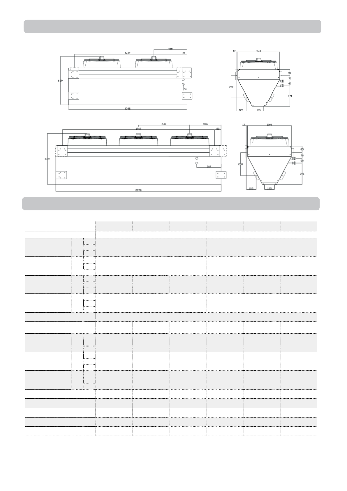
2. DIMENSIONS................................................................................................................................................... 3
3. TECHNICAL DATA......................................................................................................................................... 3
4. INSTALATION................................................................................................................................................. 4
4.1. INSTALATION SOLANO INDUSTRY-E.................................................................................................... 4
4.2. HARIZONTAL INSTALATION ................................................................................................................... 4
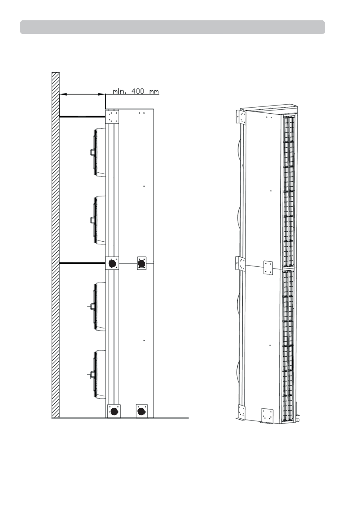
4.3. VERTICAL INSTALLATION....................................................................................................................... 5
5. CONTROL SYSTEMS .................................................................................................................................... .6
5.1. CONTROL ELEMENTS ............................................................................................................................... 6
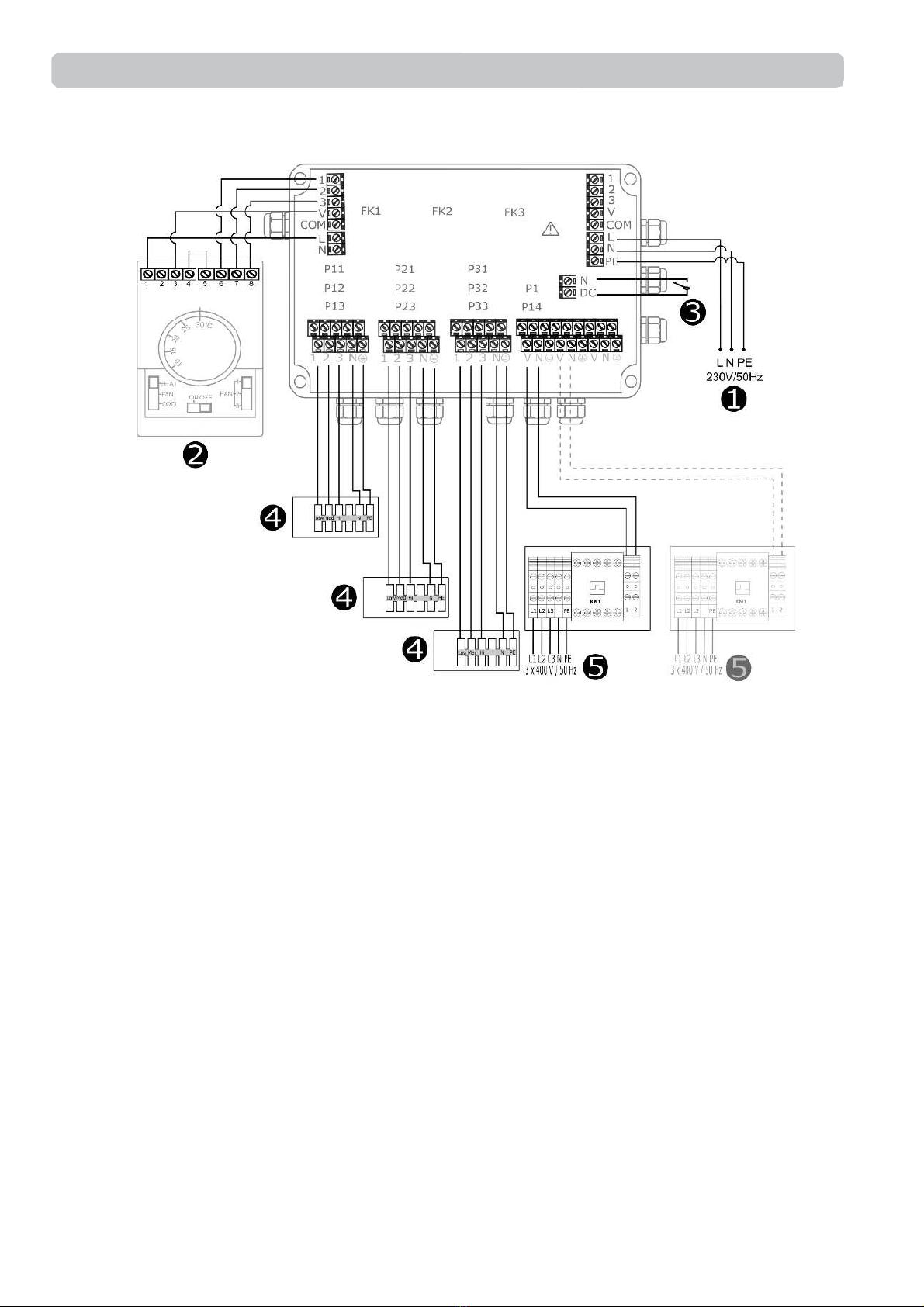
5.2. CONNECTING DIAGRAM .......................................................................................................................... 7
5.2.1 WIRING SCHEME SOLANO INDUSTRY W/N (S-C) .............................................................................. 7
5.2.2 WIRING SCHEME SOLANO INDUSTRY E (S-C) ................................................................................... 8
6. GUIDELINES FOR CONNECTION WITH POWER SUPPLY ...................................................................... 9
7. GUIDELINES FOR CONNECTION WITH PIPELINE................................................................................... 9
8. OPERATION .................................................................................................................................................... 9
9. CLEANING AND CONSERVATION ........................................................................................................... 10
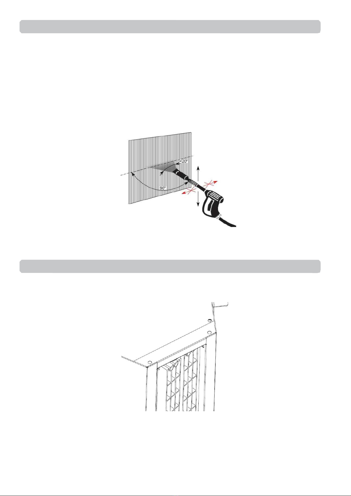
10. AIR BLADES REGULATION ..................................................................................................................... 10
11. HEATING CAPACITY ................................................................................................................................ 47
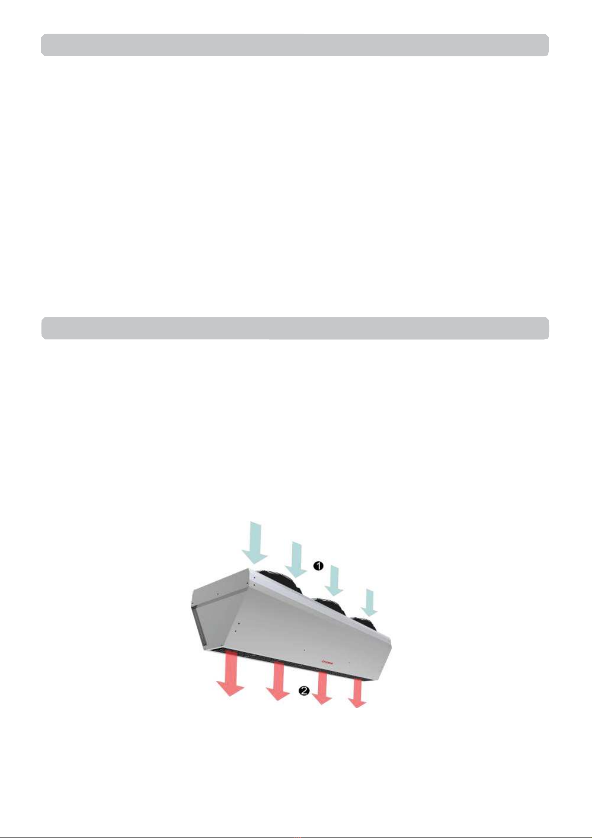
SOLANO INDUSTRY air curtain generating an air barrier which protects interior from external environment
(its temperature, solids and smog).
SOLANO INDUSTRY TYPES:
INDUSTRY-W-150 - curtain with water heat exchanger max. range 7 m*;
INDUSTRY-N-150 - curtain without heat exchanger (ambient); max. range 7,5 m*
INDUSTRY-E-150 - curtain with electric heat exchanger max. range 7 m*;
INDUSTRY-W-200 - curtain with water heat exchanger max. range 7 m*;
INDUSTRY-N-200 - curtain without heat exchanger (ambient); max. range 7,5 m*.
INDUSTRY-E-200 - curtain with electric heat exchanger max. range 7 m*;
* Vertical range of nonisothermal stream (at velocity boundary equal above 3,0 m/s),
Œair inlet; •air outlet;
1. GENERAL INFORMATION
TABLE OF CONTENTS

3
SOLANO INDUSTRY: N-150; W-150; E-150
SOLANO INDUSTRY: N-200; W-200; E-200
* INDUSTRY- W temperature increase at inlet air 10ºC and heating agent temperature 90/70ºC / INDUSTRY -E temperature increase
at inlet air 10oC
** Acoustic pressure level has been measured 3 m from the unit in a 500 m3space with a medium sound absorption coefficient.
W-150 N-150 E-150 W-200 N-200 E-200
Fan power supply [V/Hz]
230 / 50
Fan power consumption
[kW]
Step
1
0,34
0,42
7,5
0,36
0,44
11,5
2
3
Fan current
consumption [A]
Step
1
1,5
1,9
11
1,6
2,0
16,6
2
3
Air flow [m
3/h]
Step
1
4000
5100
6200
4300
5400
6500
4100
5200
6300
5100
6200
8100
5400
6500
8600
520
6300
8200
2
3
Max acoustic pressure
level [dB(A)]**
Step
1
49
54
60
51
56
62
2
3
IP
-Insulation class 54
Heating elements power supply
[V/Hz]
- - 3x400/50 - - 3x400/50
Heating capacity [kW]
Step
1
- -
9,0
10,5
12,0
- -
16,5
18,5
20,0
2
3
Current consumption
[A]
Step
1
- -
13
15
17
- -
23
26
29
2
3
Temperature rise ΔT*
[°C]
Step
1
- -
12
9
7
- -
12
9
7
2
3
Weight
[kg] 47,4 43 49,8 62 58 58
Weight of unit filled with water
[kg]
49,7 - - 64,3 - -
Max. water temperature [°C]
130 - - 130 - -
Max. water pressure [MPa]
1,6 - - 1,6 - -
Connection
[”] 3/4 - - 3/4 - -
3. TECHNICAL DATA
2. DIMENSIONS

4
SOLANO INDUSTRY air curtains are delivered with set of hangers which allow install them horizontally as
well as vertically. Installation pins and screws required for fix unit to the wall/floor/post are not included.
Max size of covered doorway:
•vertical single side installation: max width 7,5 m,
•vertical double side installation: max width 13 m,
•horizontal installation: max height level 7,5 m,.
Attention:
Screw air curtain to the wall/floor/post before first start up.
For air curatins equipped with electrical heaters is recomended to mounting electric heaters on interior side.
In case of horizontal installation use installation plate 偁and mount unit via threaded pins M10 (no included).
Single unit is mounted on 4 installation plates, two units on 6 pcs. Installation plates are used to screw units
among themselves as show on drawing.
4.2. HARIZONTAL INSTALATION
4.1. INSTALATION SOLANO INDUSTRY-E
4. INSTALATION
1
1
1

5
Vertical installation is executed via included in set installation plates 偁, which should mount unit to the floor.
Next air curtain should be putted on the first one and screwed with it via installation plate 偁and 偂, those
installation plates must be anchored to the wall/post (drawing).
4.3. VERTICAL INSTALLATION
1
2
1
1

6
S-SPLIT –splitter allow:
• Supply and protect up to three 3-steps air curtain;
• Room thermostat connection*;
•Valve acturattor connection*;
•Door switch connection*
* optional equipment
S
-C - 3-speed fan switch with room thermostat
Temperature range:
:
+10 … +30
oC
Operating temperature range
:
0 … +40
oC
IP/Insulation class:
: IP30
Max current
:
inductive
5A, resistive 6A
Power supply: 230V/50Hz
S
-TOUCH
Temperature range:
+5 … +35
oC
Operating temperature range
: -10 … +60oC
IP/Insulation class
: IP30
Power supply: 24VDC
S
-V-2-1/2” –two-way 1/2 valve with
actuator IP/Insulation class:
IP20 Power supply:
200
–240V 50/60Hz
Max water temperature: +93
oC
Max water pressure: 2,1MPa
Kvs: 3,0 m3/h
Opening time: 18 s
S
-V-3-1/2” –three-way 1/2 valve
with actuator
IP/Insulation class: IP20
Power supply:
200
–240V 50/60Hz
Max water temperature: +93
oC
Max
water pressure: 2,1MPa
Kvs: 3,4 m3/h
Opening time: 18 s
S
-DS-MEC –mechanical door switch
Operating temperature range:
-10 -+80oC
IP/Insulation class:
IP 65 Connectors: 1xNC i 1xNO
Max current:
resistive 10A –inductive 3A
Max Power load: 300VAC or
250VDC
5.1. CONTROL ELEMENTS
5. CONTROL SYSTEMS

7
N-150; W-150; N-200; W-200
To supply curtain with power connect it by
connection box closest to unit side. Protract cable
by glands and connect wires according to scheme
from box cover.
E-150; E-200
To start up curtain connect 3 x 400 V / 50 Hz
current to junction box placed between fan's
nozzles.
Nex
t connect terminals 1; 2 with S-
SPLIT
.
ŒPower supply: 230 V / 50 Hz (OMY 3x1,5 mm2)
•Air curtain step switch with thermostat S-C
(OMY 5x0,5 mm2)
HEAT –heating mode
FAN –room thermostat deactivated
COOL –cooling mode
1;2;3 –step of fan
ŽDoor contact S-DS-MEC (door closed –closed
contats; door opened –opened contacts)
(OMY 2x0,5mm2)
•Air curtain power supply (OMY 5x1,0 mm2)
•Valve S-V-2-1/2” (OMY 3x0,75mm2) or
S-V-3-1/2” (OMY 3x0,75mm2)
FK1; FK2; FK3 - overload protector (6,3 A);
5.2.1 WIRING SCHEME SOLANO INDUSTRY W/N (S-C)
5.2. CONNECTING DIAGRAM

8
ŒPower supply: 230 V / 50 Hz
(OMY 3x1,5 mm2)
•Air curtain step switch with thermostat S-C
(OMY 5x0,5 mm2)
HEAT –heating mode
FAN –room thermostat deactivated
COOL –cooling mode
1;2;3 –step of fan
ŽDoor contact S-DS-MEC (door closed –closed
contats; door opened –opened contacts) (OMY
2x0,5 mm2)
•Air curtain power supply (OMY 5x1,0 mm2)
•Power supply junction box 3x400 V /50Hz:
•
SOLANO INDUSTRY-E-150
(min. 5x4,0 mm2)(overcurent B25)
•
SOLANO INDUSTRY-E-200
(min. 5x6,0 mm2)(overcurent B40)
•
Control signal to junction box
(OMY min. 2x0,5 mm2)
FK1; FK2; FK3 - overload protector (6,3 A);
5.2.2 WIRING SCHEME SOLANO INDUSTRY E (S-C)

9
•Before connecting the power, supply check the correctness of connection of the fan motor and the
controllers.
These connections should be executed in accordance with their technical documentation.
• Before connecting the power supply check whether the mains voltage is in accordance with the voltage on
the device data shield.
• Starting the device without connecting the ground conductor is forbidden.
•Before connecting the power, supply check the correctness of connection of the fan motor and the
controllers. These connections should be executed in accordance with their technical documentation.
•Before connecting the power supply check whether the mains voltage is in accordance with the voltage on
the device data shield.
•The connection should be executed in a way which does not induce stresses.
•It is recommended to install vent valves at the highest point of the system.
•The system should be executed so that, in the case of a failure, it is possible to disassemble the device. For
this purpose it is best to use shut-off valves just by the device.
•The system with the heating medium must be protected against an increase of the heating medium
pressure above the permissible value (1.6 MPa).
•While screwing exchanger to pipeline - connecting stubs has to be hold by wrench.
•The device is designed for operation inside buildings, at temperatures above 0oC. In low temperatures
(below 0ºC) there is a danger of freezing of the medium
The manufacturer bears no responsibility for damage of the heat exchanger resulting from freezing
of the medium in the exchanger.
It is forbidden to place any objects on the heater or to hang any objects on the connecting stubs.
•The device must be inspected periodically. In the case of incorrect operation of the device it should be
switched off immediately.
It is forbidden to use a damaged device. The manufacturer bears no responsibility for damage
resulting from the use of a damaged device.
•For the time of performing inspection or cleaning the device, the electrical power supply should be
disconnected.
• In case water is drained from the device for a longer period of time, the exchanger tubes should be emptied
with compressed air.
.
8. OPERATION
7. GUIDELINES FOR CONNECTION WITH PIPELINE
6. GUIDELINES FOR CONNECTION WITH POWER SUPPLY

10
Periodically need to be checked exchanger condition. Exchanger filled with dirt causes in heat output and air
flow drop.
If cleaning of heat exchanger is needed use listed guidelines.
•Disconnect power supply of unit.
•Dismount inlet grill guard
•It is recommended to use pressured air to clean the exchanger, air stream need to be directed
perpendicular to exchanger and moved along lamellas.
Cleaning heating elements with water is prohibited
•It is prohibited to use water or sharp items to clean exchanger.
•Other installed equipment do not need be cleaned.
Air blades can be regulated in range ± 10º. To change an angle of air stream is needed to put stress at the
same time for both ends of blades
10. AIR BLADES REGULATION
9. CLEANING AND CONSERVATION
This manual suits for next models
5
Table of contents
Other Cairox Heater manuals
Popular Heater manuals by other brands

ProFusion
ProFusion Salamander PS-10241P owner's manual

Kero-Sun
Kero-Sun KPT/R 2000 instruction manual

Pur Line
Pur Line CHD210A user manual

Procom
Procom ML100HBAHR OWNER'S OPERATION AND INSTALLATION MANUAL

BE Power Equipment
BE Power Equipment PIN HE050-3 owner's manual

Silvercrest
Silvercrest 90852 operating instructions