INSTRUCTIONS
FOR
INSTALLING
ALe
SERIES
LEVER
HANDLE
SETS
OUTSIDE
LEVER
I*THRUBOLTS
ARE
PROVIDED
AND
RECOMMENDED
FOR
USE
ON
HIGH
FREQUENCY
DOORS,I
THRUBOLTS
Al
C
SERifS
ARE
PACKED
lJNASSEMBI
ED
INSIDE
BoX
I
Of{
CONVENIENCl':: &
QUICK
INS
IAl_LA! ION.
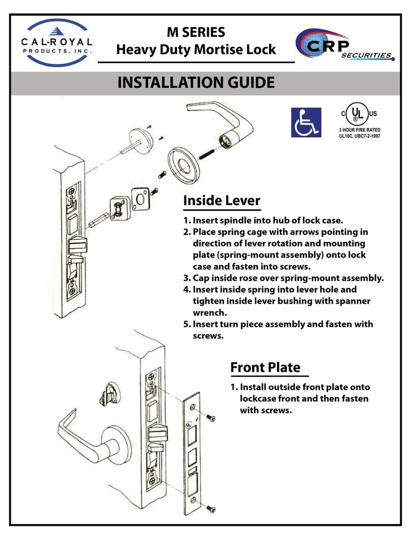
MOUNTING INSIDE LOCK BODY
Must
use M6x12
If
thru SCREW MOUNTING
INSIDE
MOUNTING SPRING CAGE
SCREW
bolt not installed,
_______
.
INSIDE
LEVER
---.
M6X12
INSIDE
ROSE
SUPPORT
SCREWS
PLATE
REMOVE
WHITE
PAPER
SPACER
BEFORE
INSTALLING
INSIDE
LEVER
,.
DOOR
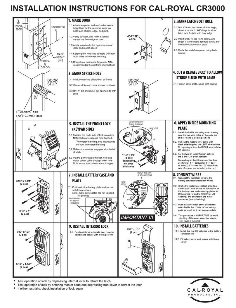
PREPARATION.
(Figure
1,)
HIGH
EDGE
OF
BEVEL
DOOR
TEMPLATE
HEIGHT
LINE
5/3'"
SUGGESTED
38"
NOTCH
FROM
FLOOR
CROSS
BORE
(CENTER
LINE
HOLE
2~'
DlA
OF
LATCHBOLT)
'CROSSBORE
HOlE21,'
DIA
!
BACKET
1,Check
loCk
lor
proper
backset
and
body
outside
stud
bolt
type
before
drilling.
2.Place
paper
template
(supplied)
on
door
and
mark
lor
holes.
Drill
the
corss,bore
hole,
and
then
the
latch
hole.
NOTE
Put
in
notches
on
21/8"
corss-bor.
hole
for
steel
door(Reler
to
lig.2.)
,
1"
(FOR
2-318'S.5.)
LATCH
HOLE
CENTER
DOOR
THICKNESS
71S'OIAFOR
2-3/S'B.S.
71S'OR
l'
FOR
2·3/4'
B.S.
71a"OIA.
HOLE
/SCREW
N1ilI--
.....
-
LATCH
BOLT
.....
BEVEL
(Figure
2.)
3.Mortise
latch
unit
front
5/32"into
door
edge
to
dimensions
shown
in
flg.2.
4.1nsert
latch
unit
with
sleeve
if
hole
is
l'
dia,
or
without
sleeve
into
7/8"
dia.
Make
certain
that
latch
bolt
bevel
laces
direction
01
closing
door.
5.Drlll
two
1/8"
dia.
holes
and
secure
latch
unit
with
combi'screws
supplied.
ASA
"
STRIKE----tt-
DISASSEMBLE
A
LOCK
INSIDE
~~~~G
A}
INSIDE
~
1
~~~
..•
~,~~""'"
INSIDE
A-
PLATE
LEVER
1.
Disassemble
inside
lever.
2.
Disassemble
inside
rose
assembly
and
inside
mounting
plate.
OUTSIDE
MOUNTING
PLATE
A
OUTSIDE
TRIM .'
\
CYLINDER
'·ASSEMBLY
KEY
TOOLS REQUIRED
PUSH PIN (PROVIDED)
NO.2
PHILLIPS
SCREWDRIVER
1I8-INCH DRILL BIT
3/B-INCH DRILL
BIT
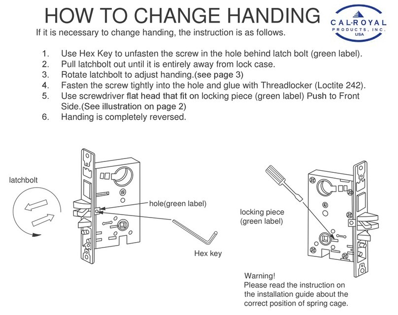
DOOR HANDING
INSIDE
lEFT
HAND
~~~RrGHTHAND
INSIDE
lEFT
HAND
____
..
___
RIGHT HAND
REVERSE
-~
~
REVERSE
BEVEL OUTSIDE BEVEL
DOOR HANDS DETERMINED FROM
OUTSIDE·
"'"
FIT
FOR
1-3/8"
DOOR
THICKNESS
Outsh;l.e
·m~r.nt,"g
B
I CENTER LINE
OUTSIDE
TRIM
Catch
hole
can
not
be
covered
by rose.
.
.'\,.,
Fohhlckness
which
Is
1-3/8':
follow
the
steps
AorBfor
adJusting:
A
1.
Screw
off
4
small
screws.'
2.
Turn
outside
mounting
plate
to
adjust
center
line
01
lock
body
to
match
"the
centerline
of
the
door.
.
3'.
Screw
4
small
screws
back
to
outside
mounting
plate
for
next
install
I
all(ln.1
8
1.
Refer
to
6A,
move
outside
lever,
depress
catch,
keep
turning
I
rose
to
make
it
fit
for
1-3/8"
door.
2.Reler
to
68
and
6C,
put
back
outside
lever.
CA45
·,
,
I
I
I
I
I
I
I
I
I
I
I
I
I
I
I
I
I
I
I
I
I
I
I
ct
I
-I,
I
I
I
I
I
I
1\
I '
I
I
I
I
I
I
I
I
&
,
1---
1
'/a"
DR
-..;!
1---
13
/,'
DR
---0-1
.'
13A3a
HOIH
0::
o
Uo<!)
Wz
~3
D..j5
:&U)
Wz
1--
3H3H
HOV.L30
13A3S
HElIH
•
