manuals.online logo
Brands
  1. Home
  2. •
  3. Brands
  4. •
  5. CalAmp
  6. •
  7. Modem
  8. •
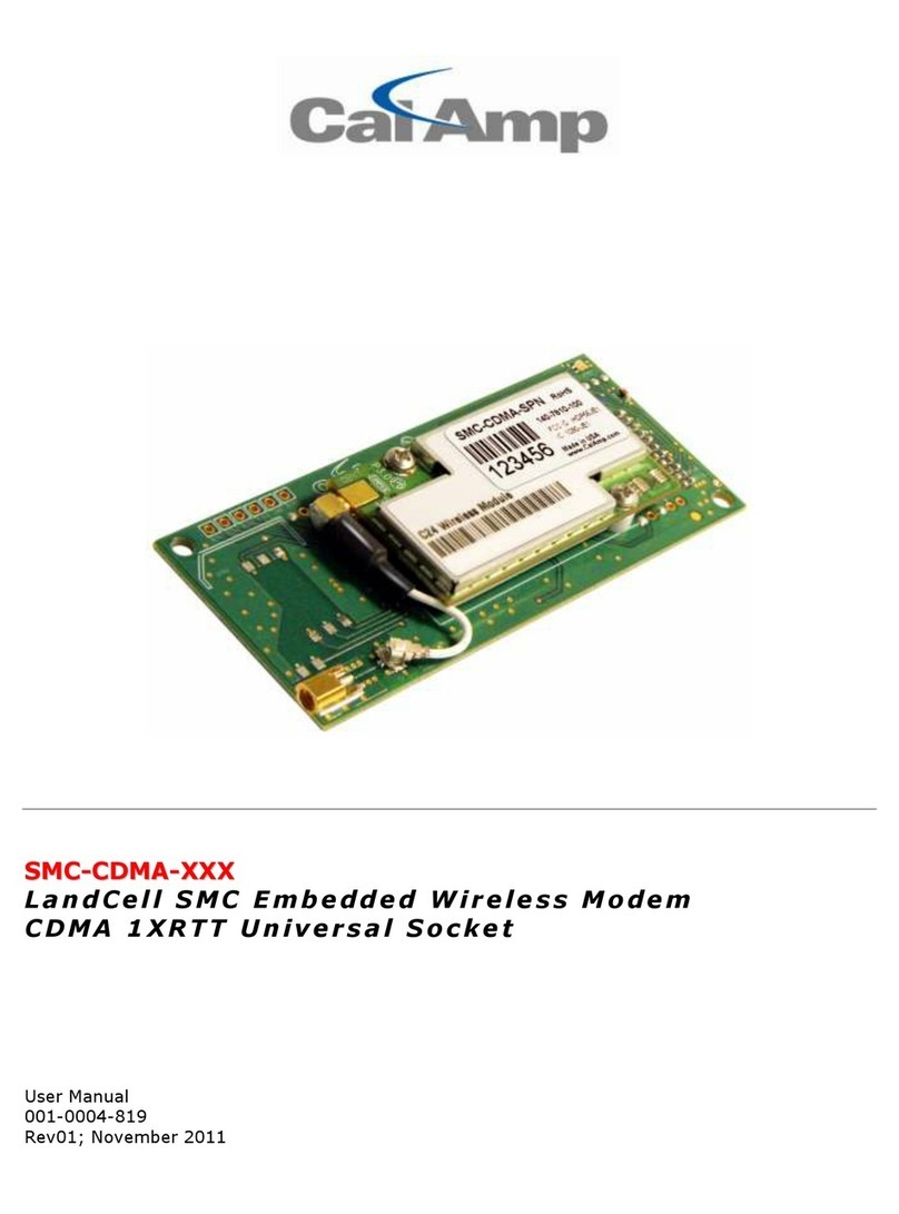
  9. CalAmp SMC-GPRS Series User manual

CalAmp SMC-GPRS Series User manual

S
SM
MC
C-
-G
GP
PR
RS
S-
-X
XX
XX
X
L a n d C e l l S M C E m b e d d e d W i r e l e s s M o d e m
G S M G P R S U n i v e r s a l S o c k e t
User Manual
001-0004-829
Rev00; October 2009
REVISION HISTORY
Rev00 Released 10/06/2009 C. Polloc
TABLE OF CONTENTS
SECTION 1 - PREFACE ...........................................................................................5
Copyright Notice...................................................................................................5
Modem Use..........................................................................................................5
Interference Issues...............................................................................................5
Mobile Application Safety.......................................................................................6
Related Documents...............................................................................................6
SECTION 2 - ABBREVIATIONS ................................................................................7
SECTION 3 - PRODUCT OVERVIEW..........................................................................8
Module Identification.............................................................................................8
General Description ..............................................................................................8
Features and Benefits ...........................................................................................8
Catalog Part Number Brea down ............................................................................8
SMC Module Description ........................................................................................9
Top side reference .............................................................................................9
Bottom side reference ......................................................................................10
Pin Descriptions...............................................................................................11
SECTION 4 - DEVELOPMENT/TEST BOARD INTERFACE.............................................12
Development/Test board .....................................................................................12
Accessories.....................................................................................................13
SECTION 5 - GETTING STARTED USING THE SMC TEST BOARD................................14
Connecting Up the SMC Test Board.......................................................................14
HyperTerminal Settings .......................................................................................14
Verify SMC Modem Connectivity ...........................................................................15
Define the Pac et Data Protocol (PDP) Context.......................................................16
Connect using the Dial-Up-Networ Connection ......................................................17
SECTION 6 - SIM CARD SPECIFIC INFORMATION....................................................20
What to do if PIN or password authentication fails?.................................................21
SECTION 7 - CALL SETUP INFORMATION ...............................................................23
Circuit Switched Data (CSD) ................................................................................23
CSD Incoming Calls .........................................................................................24
CSD Outgoing Calls..........................................................................................24
General Pac et Radio Service (GPRS)....................................................................25
GPRS Attach/Detach ........................................................................................25
Define the GPRS Context..................................................................................26
GPRS PDP Context activation/ deactivation .........................................................26
GPRS Data Mode .............................................................................................26
Short Message Service (SMS) ..............................................................................27
Initializing SMS ...............................................................................................27
Writing SMS....................................................................................................28
Reading SMS ..................................................................................................28
Deleting SMS ..................................................................................................28
Sending SMS ..................................................................................................28
Receiving SMS ................................................................................................28
SMS Status Report ..........................................................................................28
Internet Services................................................................................................29
Step-by-step instructions on how to configure and use TCP/IP communications: .....29
Maximum number of profiles defined / used: ......................................................29
SECTION 8 - SMC MODEM MODULE PROFILES ........................................................31
SECTION 9 - COMMON AT COMMAND REFERENCE GUIDE ........................................32
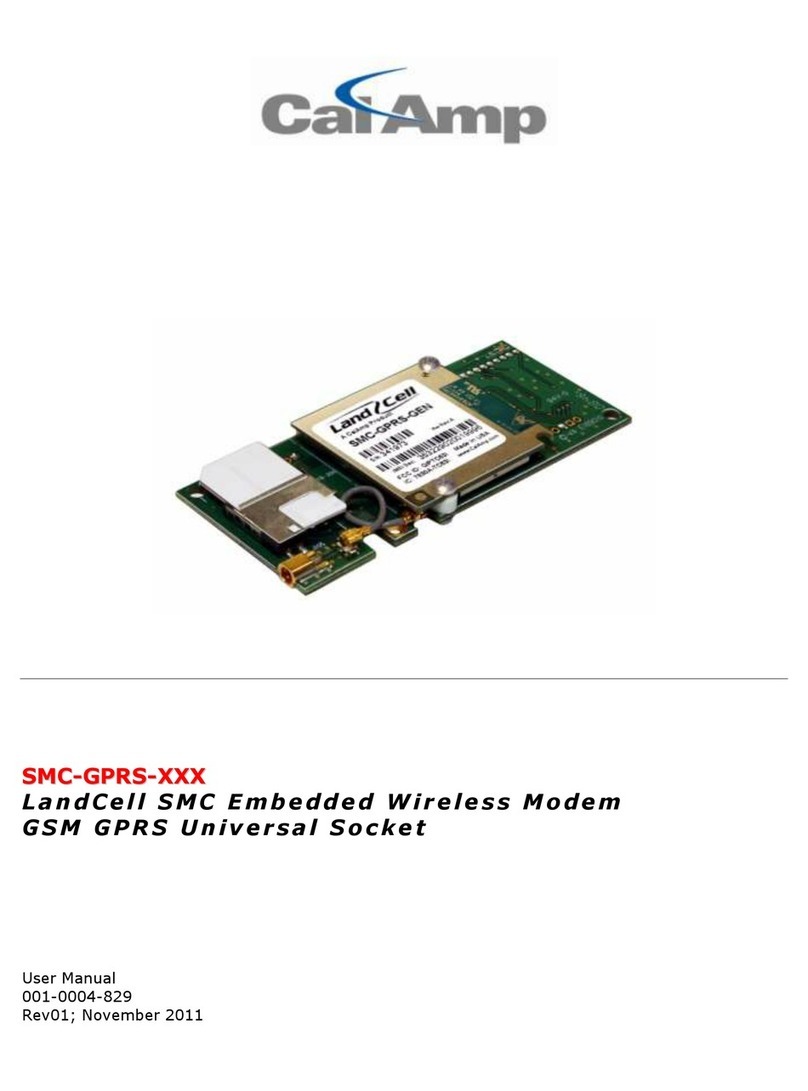
TABLE OF CONTENTS
SECTION 10 - AT COMMAND REFERENCE..............................................................34
AT Command Types ............................................................................................34
Command Line Syntax ........................................................................................34
Result Codes......................................................................................................35
Configuration Commands ....................................................................................35
Status Control Commands ...................................................................................37
Serial Interface Control Commands.......................................................................38
Security Commands............................................................................................39
Identification Commands .....................................................................................40
Call Related Commands.......................................................................................40
Networ Service Commands ................................................................................42
Internal Internet Service Commands.....................................................................45
GPRS Commands................................................................................................46
Short Message Service (SMS) Commands..............................................................49
SIM Related Commands ......................................................................................50
Hardware Related Commands ..............................................................................51
Factory Default AT Command values.....................................................................52
SECTION 11 - SPECIFICATIONS...........................................................................54
General Specifications .........................................................................................54
Data Transmission Specifications ..........................................................................55
Mechanical Specifications.....................................................................................56
SECTION 12 - SERVICE AND SUPPORT .................................................................57
Product Warranty, RMA and Contact Information ....................................................57
RMA Request .....................................................................................................57
Product Documentation .......................................................................................57
Technical Support...............................................................................................57
A
AP
PP
PE
EN
ND
DI
IX
X
A
A
–
–
P
PO
OW
WE
ER
R
S
SU
UP
PP
PL
LY
Y
D
DE
ES
SI
IG
GN
N
I
IN
NF
FO
OR
RM
MA
AT
TI
IO
ON
N...............................................58
Power Supply Issues ...........................................................................................58
SMC-GPRS Power Supply Requirements ................................................................59
A
AP
PP
PE
EN
ND
DI
IX
X
B
B
–
–
C
CR
RE
EA
AT
TI
IN
NG
G
A
A
D
DI
IA
AL
L-
-U
UP
P
N
NE
ET
TW
WO
OR
RK
KI
IN
NG
G
C
CO
ON
NN
NE
EC
CT
TI
IO
ON
N ...............................61
Windows XP .......................................................................................................61
Add Standard Windows Modem .........................................................................61
Configuring the Modem ....................................................................................65
Create a Dial-Up Networ ing (DUN) Connection...................................................66
Windows Vista....................................................................................................73
Add Standard Windows Modem .........................................................................73
Configuring the Modem ....................................................................................77
Create a Dial-Up Networ ing (DUN) Connection...................................................78
A
AP
PP
PE
EN
ND
DI
IX
X
C
C
–
–
W
WA
AR
RR
RA
AN
NT
TY
Y
S
ST
TA
AT
TE
EM
ME
EN
NT
T ....................................................................84
001-0004-829 Rev00
Page 5 of 84
S
SE
EC
CT
TI
IO
ON
N
1
1
-
-
P
PR
RE
EF
FA
AC
CE
E
Copyright Notic
©2009 CalAmp. All Rights Reserved.
This manual covers the operation of the CalAmp SMC-GPRS Embedded Wireless Modem.
Specifications described are typical only and are subject to normal manufacturing and
service tolerances.
CalAmp reserves the right to modify the equipment, its specification or this manual without
prior notice, in the interest of improving performance, reliability or servicing. At the time of
publication all data is correct for the operation of the equipment at the voltage and/or
temperature referred to. Performance data indicates typical values related to the particular
product.
No part of this documentation or information supplied may be divulged to any third party
without the express written consent of CalAmp.
Products offered may contain software which is proprietary to CalAmp. The offer or supply
of these products and services does not include or infer any transfer of ownership.
Mod m Us
The SMC-GPRS modem is designed and intended for use in fixed and mobile applications.
“Fixed” assumes the device is physically secured at one location and not easily moved to
another location. Please eep the cellular antenna of the SMC-GPRS at a safe distance from
your head and body while the modem is in use (see below).
Important
Maintain a distance of at least 20 cm (8 inches) between the transmitter’s antenna and any
person while in use. This modem is designed for use in applications that observe the 20 cm
separation distance.
Int rf r nc Issu s
Avoid possible radio frequency (RF) interference by following these guidelines:
•The use of cellular telephones or devices in aircraft is illegal. Use in aircraft may
endanger operation and disrupt the cellular networ . Failure to observe this
restriction may result in suspension or denial of cellular services to the offender,
legal action or both.
•Do not operate in the vicinity of gasoline or diesel-fuel pumps unless use has been
approved and authorized.
•Do not operate in locations where medical equipment that the device could interfere
with may be in use.
•Do not operate in fuel depots, chemical plants, or blasting areas unless use has been
approved and authorized.
•Use care if operating in the vicinity of protected personal medical devices, i.e.,
hearing aids and pacema ers.
•Operation in the presence of other electronic equipment may cause interference if
equipment is incorrectly protected. Follow recommendations for installation from
equipment manufacturers.
001-0004-829 Rev00
Page 6 of 84
Mobil Application Saf ty
•Do not change parameters or perform other maintenance of the SMC-GPRS while
driving.
•Road safety is crucial. Observe National Regulations for cellular telephones and
devices in vehicles.
•Avoid potential interference with vehicle electronics by correctly installing the
SMC-GPRS. CalAmp recommends installation by a professional.
R lat d Docum nts
[1] Cinterion Wireless Application Developer’s Guide WM_AN24_DevGuide_v07
[2] Cinterion Wireless AT Command Set, TC63i TC63i_ATC_V01.100
[3] Cinterion Power Supply for Wireless Applications WM_AN26_PwrSupply_v04
001-0004-829 Rev00
Page 7 of 84
S
SE
EC
CT
TI
IO
ON
N
2
2
-
-
A
AB
BB
BR
RE
EV
VI
IA
AT
TI
IO
ON
NS
S
Abbreviation Description
APN Access Point Name
CDMA Code Division Multiple Access
CSD Circuit Switched Data
CTS Clear to Send
DCD Data Carrier Detect
DCE Data Communication Equipment
DTE Data Terminal Equipment
EDGE Enhanced Data rates for Global Evolution
GPRS General Packet Radio Service
GPS Global Positioning System
GSM Global System for Mobile communication
IMEI International Mobile Electronic Identity
LED Light Emitting Diode
ME Mobile Equipment
MS Mobile Station
OTA Over the Air
PDP Packet Data Protocol
PPP Point to Point Protocol
PRL Preferred Roaming List
RSSI Receive Signal Strength Indication
RX Receive
TA Terminal Adapter
TE Terminal Equipment
TX Transmit
001-0004-829 Rev00
Page 8 of 84
S
SE
EC
CT
TI
IO
ON
N
3
3
-
-
P
PR
RO
OD
DU
UC
CT
T
O
OV
VE
ER
RV
VI
IE
EW
W
Modul Id ntification
Lab l Information
The label contains the CalAmp part number, serial number, FCC ID, and the IMEI number.
IMEI: The International Mobile Equipment Identifier of the cellular module in decimal format.
G n ral D scription
The LandCell SMC-GPRS embedded wireless modem from CalAmp is a versatile, cost-effective
wireless communications device designed for the industry-standard universal soc et. Quad-
band GSM/GPRS offers compatibility with cellular networ s around the world.
The SMC-GPRS embedded modem is ideal for OEM customers loo ing to add cellular wireless
communications to their products. Applications include: monitoring, metering, diagnostics,
security, data collection, and other applications requiring wireless connectivity.
F atur s and B n fits
Industry-standard Universal Soc et open interface
GSM/GPRS Quad-Band 850/900/1800/1900 MHz
Supports GPRS Class 12
TCP/IP stac access via AT commands
Circuit Switch Data
Short Message Service (SMS)
Pac et Data
MMCX Antenna Connector
Optimized for OEM applications
Catalog Part Numb r Br akdown
SMC-GPRS-XXX (XXX = Carrier Identifier)
GEN = Generic
001-0004-829 Rev00
Page 9 of 84
SMC Modul D scription
Top sid r f r nc
Fig. 2.1 SMC-GPRS Top Side
SMC-GPRS top side components:
1. Pow r: Green LED indicating cell module power on.
2. DCD: Red LED indicating Data Carrier Detect from cellular networ .
3. RF (ant nna): MMCX soc et, primary antenna connection.
4. SIM: SIM Card Slot (SIM card purchased separately).
5. GSM C ll Modul
4
3
5
2
1
001-0004-829 Rev00
Page 10 of 84
Bottom sid r f r nc
Fig. 2.2 SMC-GPRS Bottom Side
SMC-GPRS bottom side soc et pins:
1. VCC/GND pins
2. –R s t/GND pins
3. SERIAL pins
Figure 2.3 SMC Pins, Top View
2
1
3
001-0004-829 Rev00
Page 11 of 84
Pin D scriptions
Pin # Pin
Nam
I/O
Typ D scription
24 -RESET
Input
This signal is used to force a reset procedure by providing a low
level for at least 10 ms. Data stored in volatile memory will be lost.
This line must be driven by an open drain or open collector. If
unused, eep line open.
26, 41, 63
GND Ground
33 -RTS Input Request to Send. Signal used for hardware flow control
34 -RXD Output Received Data. Line used to send received data and modem
responses to the DTE (Data Terminal Equipment)
35 -TXD Input Transmitted Data. Line used to send data and transmit commands
from the DTE.
36 -RI Output Ring Indicator. Output low (ON) indicates the presence of a ring
signal.
37 -DSR Output Data Set Ready. Line used to indicate modem status to the DTE.
38 -CTS Output Clear to Send. Line controlled by the modem to indicate whether or
not the modem is ready to transmit data.
39 -DCD Output Data Carrier Detect. Line asserted by the DTE to indicate connection
status.
40 -DTR Input Data Terminal Ready. Line asserted by the DTE to indicate
that it is
ready to transmit or receive data.
61 VCC Power +5 VDC ±0.25 VDC
Digital Input lines: Input High, Min 3.675 V
Input Low, Max 1.4 V
Digital Output Lines: Output High, Min 4.0 V
Output Low, Max 0.4 V
Digital Line Current Drive: 2.0 mA
NOTE: VCC is th maximum voltag rating on S rial UART input pins.
001-0004-829 Rev00
Page 12 of 84
S
SE
EC
CT
TI
IO
ON
N
4
4
-
-
D
DE
EV
VE
EL
LO
OP
PM
ME
EN
NT
T/
/T
TE
ES
ST
T
B
BO
OA
AR
RD
D
I
IN
NT
TE
ER
RF
FA
AC
CE
E
D v lopm nt/T st board
The Development/Test board is required to interface the SCM-GPRS modem to a standard RS232
serial connection. The SMC test board also supplies the SMC-GPRS modem with the required +5VDC
supply voltage from an externally supplied 10 to 28 VDC power source, +12VDC typical.
Figure 4.1 SMC modem wit DK test board
SMC-GPRS test board components:
1. SMC-GPRS mod m
2. MMCX to SMA RF cabl : Provides connection to external antenna.
3. RS-232 Port: Standard D-Sub, 9 pin, female connector.
4. Pow r Conn ctor: Molex 4-pos 3MM receptacle (lower left: GND, lower right: +VDC).
5. Blu LED: Power Indicator
6. Y llow LED: DCD Indicator
7. Gr n LED: RXD Indicator
8. R d LED: TXD Indicator
9. RESET Switch: Bottom side of DK test board (under SIM card holder)
Not : USB connector reserved for future use.
1
5
4
6
7
8
2
3
9
001-0004-829 Rev00
Page 13 of 84
RS-232 S rial Port Int gration Param t rs
Table 4.2 provides the serial cable design information for the SMC-GPRS using the DK test
board.
Table 4.2 Standard RS-232 DE-9 Pin out
Pin Name Direction Description
1 CD «— Carrier Detect
2 RX «— Receive Data
3 TX —» Transmit Data
4 DTR —» Data Terminal Ready
5 GND System Ground
6 DSR «— Data Set Ready
7 RTS —» Request to Send
8 CTS «— Clear to Send
9 RI «— Ring Indicator
Note: Direction is DTE relative DCE
.
Table 4.3 Default RS-232 Communication Parameters
Bits Per Second
115,200
Data Bits 8
Parity None
Stop Bits 1
Flow Control Hardware
Acc ssori s
Antenna 3” Mag Mount Antenna L2-ANT0003
Antenna Adapter Cable MMCX to SMA cable 497-7500-003 or
697-7500-003
Power Supply 110 VAC input
DC Power Cable
150-7001-001
150-7500-002
Interface Cable Serial Cable L2-CAB0002
Primary Ant nna
The primary antenna connection on the SMC-GPRS is a MMCX connector. Mounting options and
cable lengths are user’s choice and application specific.
001-0004-829 Rev00
Page 14 of 84
S
SE
EC
CT
TI
IO
ON
N
5
5
-
-
G
GE
ET
TT
TI
IN
NG
G
S
ST
TA
AR
RT
TE
ED
D
U
US
SI
IN
NG
G
T
TH
HE
E
S
SM
MC
C
T
TE
ES
ST
T
B
BO
OA
AR
RD
D
This section describes the use of the SMC test board to set up the SMC modem for internet access
using HyperTerminal and a dial-up networ connection (DUN). Please refer to App ndix B for
details on setting up a modem driver for a DUN connection.
Conn cting Up th SMC T st Board
Connect the Power cable, RS232 cable, Antenna cable to the SMC test board as shown in Figure 5.1.
Insert an active SIM card into the SMC modem.
Figure 5.1 SMC test board connections
Hyp rT rminal S ttings
Open a HyperTerminal session and configure the properties for the COM port used to connect the
SMC test board.
Set HyperTerminal properties for:
Bits per second: 115200
Data bits: 8
Parity: Non
Stop bits: 1
Flow control: Hardwar
001-0004-829 Rev00
Page 15 of 84
V rify SMC Mod m Conn ctivity
Power on the SMC test board (+12VDC typical) and observe the HyperTerminal window for
^SYSSTART
, indicating the SMC modem successfully powered on.
Figure 5.2 HyperTerminal screen responses
The ATI command prints the cell module product information. If you get an Error or no
communication, verify the modem is connected to the proper COM port and powered on. Refer to
Figure 5.2 for all the AT commands listed below.
Confirm your SIM card is properly installed with the AT^SCID command. A reply of ^SCID:<20
digit CID number> indicates the modem recognizes the SIM card and displays it’s ID number.
Confirm the phone number currently in the modem with the AT+CNUM command. It should be 11
digits i.e. 18052162288. For some carriers the phone number may not display but will respond with
“OK”. If the SIM card is not in the unit or not activated properly, the modem will reply with “ERROR”.
Verify the modems International Mobile Equipment Identity (IMEI) number with the AT+CGSN
command. The IMEI is used to identify GSM mobile equipment to the GSM networ .
001-0004-829 Rev00
Page 16 of 84
Confirm that the SIM’s PIN has been authenticated by the networ using the AT+CPIN? command.
The reply should read “+CPIN: READY”. See Section 6 for SIM related information if “READY” does
not display.
Verify good signal strength with the AT+CSQ command. A typical reply is +CSQ 25, 99. The first
number is signal strength and ranges from 0 to 31 (the higher the number, the stronger the signal).
D fin th Pack t Data Protocol (PDP) Cont xt
Next, the Access Point Name (APN) must be defined using the PDP Context command
AT+CGDCONT=1,“IP”,<apn> command. The <apn> is the access point name for a specific
cellular provider (for example AT+CGDCONT=1,”IP”,internet). The At+CGDCONT? command can be
issued to verify the PDP Context information.
The PDP context information can be set to non-volatile by issuing the
AT^SCFG=GPRS/P rsist ntcont xts=1 command. GPRS PDP context will not be reset by an
AT&F command. Refer to Figure 5.3.
Figure 5.3 Set PDP Contexts, APN
Exit HyperTerminal before attempting to connect using a Dial-Up-Networ ing connection.
001-0004-829 Rev00
Page 17 of 84
Conn ct using th Dial-Up-N twork Conn ction
Go to the Networ Connections screen and double clic on the newly created Dial-Up connection (i.e.
SMC-GPRS).
When the connect window appears, set the username and password as defined for your carrier
(usually blan ). Enter the phone number as *99***1# and clic the Dial button.
001-0004-829 Rev00
Page 18 of 84
The modem will attempt to connect to the provider networ . If the configured baud rate for the COM
port, the modem, and the DUN do not match, the DUN will not be able to tal to the modem
properly and you will get a hardware error message. Otherwise the DUN will contact the cellular
networ and authenticate the user on the networ .
Once connected you should be able to browse the internet thorough the DUN session. To confirm
this, disable any other networ connections you may have running.
001-0004-829 Rev00
Page 19 of 84
Right clic on the connected Dial-Up connection icon and select the Details tab. The status of the
connection will be displayed, including the IP address assigned by the carrier networ .
001-0004-829 Rev00
Page 20 of 84
S
SE
EC
CT
TI
IO
ON
N
6
6
-
-
S
SI
IM
M
C
CA
AR
RD
D
S
SP
PE
EC
CI
IF
FI
IC
C
I
IN
NF
FO
OR
RM
MA
AT
TI
IO
ON
N
The SIM card can be used to store a Personal Idetification Number (PIN) to authenticate users on
the networ .
The AT+CPIN write command can be used to enter one of the passwords listed below. The read
command can be used to chec whether or not the ME is waiting for a password, or which type of
password is required.
This may be for example the SIM PIN1 to register to the GSM networ , or the SIM PUK1 to replace a
disabled SIM PIN1 with a new one, or the PH-SIM PIN if the client has ta en precautions for
preventing damage in the event of loss or theft etc. If requested by the ME AT+CPIN may also be
used for the SIM PIN2 or SIM PUK2. If no PIN1 request is pending (for example if PIN1
authentication has been done and the same PIN1 is entered again) SMC modem responds "+CME
ERROR: operation not allowed"; no further action is required.
Each time a password is entered with AT+CPIN the module starts reading data from the SIM. The
duration of reading varies with the SIM card. This may cause a delay of several seconds before all
commands which need access to SIM data are effective.
AT+CPIN=<pin>[, <new pin>]
<pin>: Password (string type), usually SIM PIN1. If the requested password was a Pin Unloc Code
(PUK), such as SIM PUK1 or PH-FSIM PUK or another password, then <pin> must be followed by
<new pin>.
<new pin>: If the requested code was a PUK: specify a new password or restore the former disabled
password. See section “What to do if PIN or password authentication fails?” for more information
about when you may need to enter the PUK.
Successful PIN authentication only confirms that the entered PIN was recognized and correct. The
output of the result code OK does not necessarily imply that the mobile is registered to the desired
networ . Typical example: PIN was entered and accepted with OK, but the ME fails to register to the
networ . This may be due to missing networ coverage, denied networ access with currently used
SIM card, no valid roaming agreement between home networ and currently available operators etc.
The SMC modem offers various options to verify the present status of networ registration: For
example, the AT+COPS command indicates the currently used networ . With AT+CREG you can also
chec the current status and activate an unsolicited result code which appears whenever the status
of the networ registration changes (e.g. when the ME is powered up, or when the networ cell
changes).
The <pin> and <new pin> can also be entered in quotation mar s (e.g. "1234").
To chec the number of remaining attempts to enter the passwords use the AT^SPIC command.
See AT+CPWD and AT^SPWD for information on passwords.
See AT+CLCK and AT^SLCK for information on loc types.

Other manuals for SMC-GPRS Series

1

This manual suits for next models

2

Other CalAmp Modem manuals

CalAmp GUARDIAN User manual

CalAmp

CalAmp GUARDIAN User manual

CalAmp LMU 2630MB User manual

CalAmp

CalAmp LMU 2630MB User manual

CalAmp 819-GPRS series User manual

CalAmp

CalAmp 819-GPRS series User manual

CalAmp GUARDIAN User manual

CalAmp

CalAmp GUARDIAN User manual

CalAmp 882-GPRS series User manual

CalAmp

CalAmp 882-GPRS series User manual

CalAmp Vanguard 5530 User manual

CalAmp

CalAmp Vanguard 5530 User manual

CalAmp LandCell 819?1XRT User manual

CalAmp

CalAmp LandCell 819?1XRT User manual

CalAmp 882?GPRS?GEN User manual

CalAmp

CalAmp 882?GPRS?GEN User manual

CalAmp TSLM User manual

CalAmp

CalAmp TSLM User manual

CalAmp SMC-CDMA Series User manual

CalAmp

CalAmp SMC-CDMA Series User manual

CalAmp GEMINI G3 User manual

CalAmp

CalAmp GEMINI G3 User manual

CalAmp 819-1XRT SERIES User manual

CalAmp

CalAmp 819-1XRT SERIES User manual

CalAmp Dataradio HiPR-900 User manual

CalAmp

CalAmp Dataradio HiPR-900 User manual

CalAmp 882?EVDO?XXX User manual

CalAmp

CalAmp 882?EVDO?XXX User manual

CalAmp 822-1XRT User manual

CalAmp

CalAmp 822-1XRT User manual

CalAmp SMC-GPRS Series User manual

CalAmp

CalAmp SMC-GPRS Series User manual

CalAmp Integra-Tr User manual

CalAmp

CalAmp Integra-Tr User manual

CalAmp Integra-Tr User manual

CalAmp

CalAmp Integra-Tr User manual

CalAmp NU850 User manual

CalAmp

CalAmp NU850 User manual

Popular Modem manuals by other brands

2-Wire HomePortal 1500CW user guide

2-Wire

2-Wire HomePortal 1500CW user guide

B-Link Usb modem quick start guide

B-Link

B-Link Usb modem quick start guide

Multitech MTSMC-E manual

Multitech

Multitech MTSMC-E manual

Black Box MD5010A Specifications

Black Box

Black Box MD5010A Specifications

Black Box LDM-MR 19.2 instruction manual

Black Box

Black Box LDM-MR 19.2 instruction manual

Black Box ME109A Specifications

Black Box

Black Box ME109A Specifications

Multitech MultiModem MT5634ZBA-V.92 quick start guide

Multitech

Multitech MultiModem MT5634ZBA-V.92 quick start guide

Multitech MultiModem MTCBA-C-N1 user guide

Multitech

Multitech MultiModem MTCBA-C-N1 user guide

Multitech MultiModem SocketModem MT9234 Series AT Commands Reference Guide

Multitech

Multitech MultiModem SocketModem MT9234 Series AT Commands Reference Guide

Uni-Com USRobotics Courier Lite 5686G-PRO user guide

Uni-Com

Uni-Com USRobotics Courier Lite 5686G-PRO user guide

Multitech MultiModem ZPX quick start guide

Multitech

Multitech MultiModem ZPX quick start guide

Zte Z288L user manual

Zte

Zte Z288L user manual

Cisco 605 quick start

Cisco

Cisco 605 quick start

MTX MTX-GTW Hardware user's guide

MTX

MTX MTX-GTW Hardware user's guide

Tramigo T21 installation guide

Tramigo

Tramigo T21 installation guide

D-Link DSL-320B Technical specifications

D-Link

D-Link DSL-320B Technical specifications

Motorola 3460 Fast'R reference guide

Motorola

Motorola 3460 Fast'R reference guide

Dataradio G3 user manual

Dataradio

Dataradio G3 user manual

manuals.online logo
manuals.online logoBrands
  • About & Mission
  • Contact us
  • Privacy Policy
  • Terms and Conditions

Copyright 2025 Manuals.Online. All Rights Reserved.