manuals.online logo
Brands
  1. Home
  2. •
  3. Brands
  4. •
  5. CalAmp
  6. •
  7. Modem
  8. •
  9. CalAmp LMU 2630MB User manual

CalAmp LMU 2630MB User manual

LMU 2630MB Quick Install Guide
This guide provides instructions on how to install and set up
the Safe Fleet LMU (Location Messaging Unit) model 2630MB
(part # VLP-LMUE1Y1). This device sends GPS data over
cellular networks to an online web server, allowing customers
to track the location of their vehicles using software.
Customers and installers should have received an Installation Record document (see sample below) with the
Device IDs column pre-populated. The Device ID (sometimes referred to as ESN) is a 10 digit number found on
the label of the LMU, and is required in order to properly provision and test your device.
1 Record Vehicle Installation
Contact Support
• Phone: 1-844-899-7366
• Email: PTsupport@safeeet.net
© Safe Fleet | May 2022 | All rights reserved | Part #: 700-1283 R1
NOTE: DVR Firmware Compatibility with LMU 2630MB
When installing the LMU 2630MB with a Safe Fleet
recorder, you’ll need to ensure that your recorder has the
most current rmware. To conrm your rmware version,
please contact Technical Support for assistance.
If the Installation Record is unavailable, contact the eet administrator for it or create a form and record the
following vehicle information for each LMU Controller that is installed.
Device ID: Bus ID:
License Plate No: Odometer:
FDate Installed: Notes:
The following checklist will help you track the LMU installation process. Ensure that everything on this
checklist is veried before wrapping up.
Service & Support
If your product is to be returned for service, please contact the Safe Fleet technical support team, provide the part and/or serial
# of your unit, and ask for a Return Merchandise Authorization (RMA) number.
An RMA # allows the support team to better track your product when it comes in for service. Please show the RMA # on the
outside of the package.
ANY PRODUCT SENT WITHOUT AN RMA # MAY BE REFUSED!
This guide along with other documentation and product warranties can be found on the Safe Fleet
Community website https://community.safeeet.net/
To access LMU documentation, scan the QR code on the right with your mobile device.
2002/96/EC (WEEE directive): This product cannot be disposed of as unsorted municipal waste in the European
Union. For proper recycling, return the product to your local supplier upon the purchase of equivalent new
equipment, or dispose of it at designated collection points, for more information, see www.recyclethis.info.
2006/66/EC (battery directive): This product does not contain batteries.
Record Installation Details
Device ID License Plate
Bus ID Install Date
Odometer
Power Harness
Check for tight mounting of hardware and connections
LMU Position
Check for tight mounting of LMU
Label is facing outwards towards sky
LEDs
Ensure that both Comm and GPS LED light up solid
Recorder (Optional)
Ensure that DVR Firmware is compatible with the LMU
Installation Checklist
Documentation and Warranty
Use the following diagram to connect the LMU Controller with the other system components.
Install signal connections as required.
3 Connect LMU Controller
Aux 1
Cable Harness
and Connector
LMU Controller Connections
Typical System Setup for DVR with 2x2 GPS Socket
LMU
to GPS
Adaptor
Cable
Power Harness
060-1018
060-1012
GPS4-CBL
(20ft / 6.1m)
Red, black, white wires
LMU Controller VLP-LMU26M
LMU Controller
Harness LED end
Comm LED
GPS LED
1x5 Microfit
connector
2x2 Microfit
connector
To
DVR
options
Pin 1
Pin 1
Pin 11
Pin 11
Pin 10Pin 10
Pin 20Pin 20
GPS4 Extension
Cable
ETHERNET POWER
SIGNALS GPS
CAM2CAM1
CONTROL
ALARM
Battery Negative (black)
Vehicle + 12/24V (red)
Ignition (white)
3 wires
3A
3A
Black wire from pin 16 to black on
extension cable
Pin 16 - Alarm Button
(black wire, active low)
Pin 3 - Stop Arm
(blue wire, active high)
Orange wire from pin 12 to red on
extension cable
Pin 12 - Alarm Button
(orange wire, active low)
Alarm Button 060-0061
With the supplied alcohol wipe, clean the vehicle surface where the LMU will be installed, ensuring to choose a
dry location with easy access to the electrical panel and cable connections.
The LMU contains a built-in GPS antenna, which can be obstructed by metal objects. The best place to mount
the LMU for optimal GPS reception is on top of the front dash panel, with the label facing out towards the sky.
2 Install and Mount the LMU Controller 4 Install Signal Connections
Once you connect the harness, you’ll need to verify whether the device is powered and communicating with
the Safe Fleet Cloud servers. The following table describes the LED patterns on the LMU. Ensure that the
device reaches solid orange and solid green before moving onto the next step.
Once all of your devices are installed, powered, and communicating properly, you’ll need to provision the
devices with Safe Fleet software. A detailed walk-through of the provisioning procedure can be found on our
Safe Fleet Community customer support portal. Open a web browser on your device and navigate to https://
community.safeeet.net/installer. Then, select the LMU provisioning procedure and follow the instructions
outlined on that page.
5 Verify LEDs
6 Provision the LMU
LED Status Indicator
Comm LED - Orange Condition GPS LED - Green Condition
Off Modem Off Off GPS Off
Slow Blinking Comm On - Searching Slow Blinking GPS On
Fast Blinking Network Available Fast Blinking GPS Time Sync
Fast Blink to Solid Registered - No Inbound
Acknowledgment
Solid GPS Fix
Solid Registered - Inbound
Acknowledgment
NOTE: Safe Fleet Community Access
You’ll need to log into the SF Community’s installer page in order to view the tutorials. If you do not have a
username and password to the site, then you’ll need to contact the customer support team for assistance.
IMPORTANT: DH Series
If you have a DH video recorder (except DH4C), scan the QR code included in the documentation section
at the end of this guide to access instructions on how to connect the LMU to the video recorder.
Alarm Button / Extension Cable
To connect the extension cable,
use supplied butt connectors (2x)
to connect the alarm button ying
leads to the extension harness
ying leads (Red to Red, Black to
Black). Cut the 2x1 Molex connector
off the extension cable and use
supplied butt connectors (2x) to
connect the extension harness
red wire to the LMU harness pin
12, orange wire. Then, connect the
extension harness black wire to the
LMU harness pin 16, black wire.

Other manuals for LMU 2630MB

1

This manual suits for next models

1

Other CalAmp Modem manuals

CalAmp 819-GPRS series User manual

CalAmp

CalAmp 819-GPRS series User manual

CalAmp 819-1XRT SERIES User manual

CalAmp

CalAmp 819-1XRT SERIES User manual

CalAmp Integra-Tr User manual

CalAmp

CalAmp Integra-Tr User manual

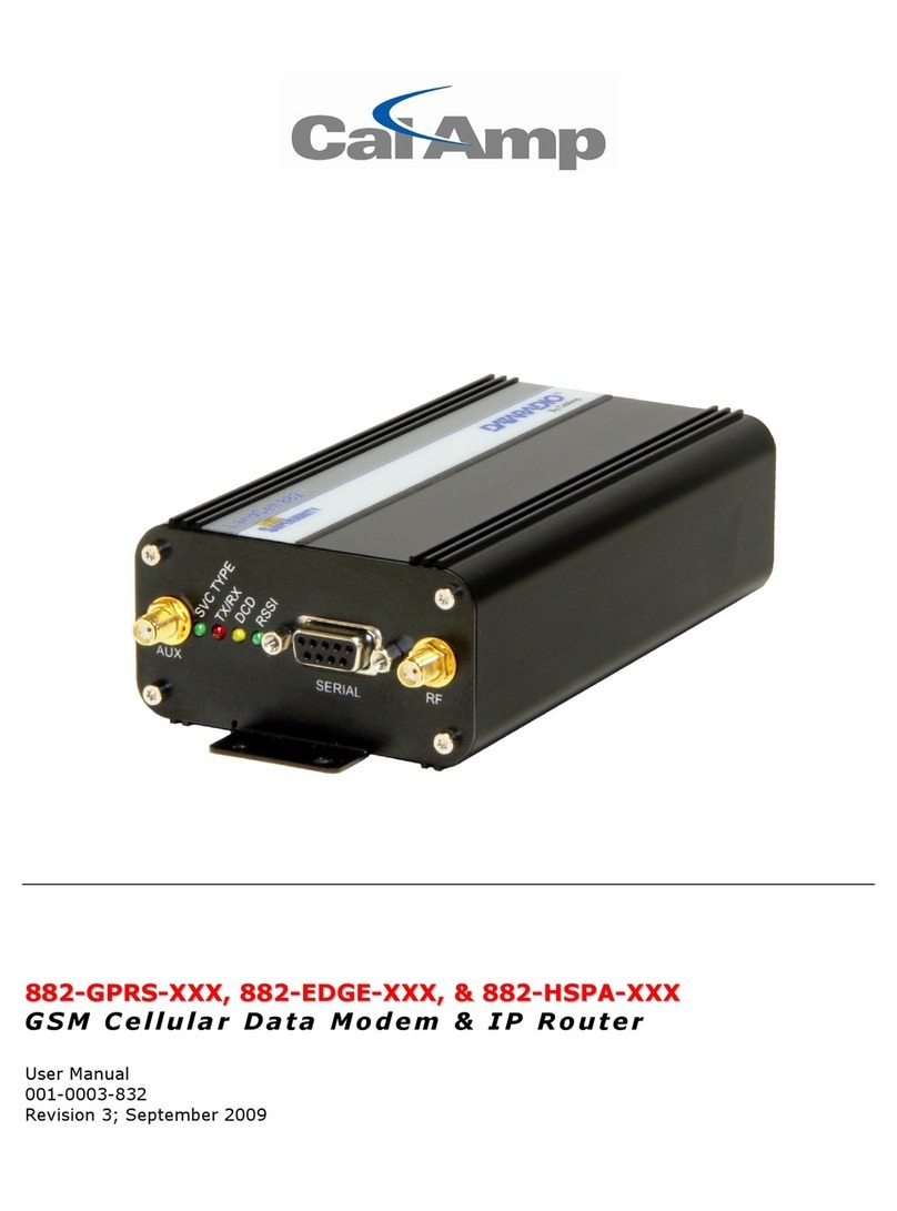
CalAmp 882-GPRS series User manual

CalAmp

CalAmp 882-GPRS series User manual

CalAmp NU850 User manual

CalAmp

CalAmp NU850 User manual

CalAmp 822-1XRT User manual

CalAmp

CalAmp 822-1XRT User manual

CalAmp LandCell 819?1XRT User manual

CalAmp

CalAmp LandCell 819?1XRT User manual

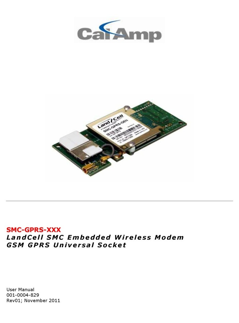
CalAmp SMC-GPRS Series User manual

CalAmp

CalAmp SMC-GPRS Series User manual

CalAmp GEMINI G3 User manual

CalAmp

CalAmp GEMINI G3 User manual

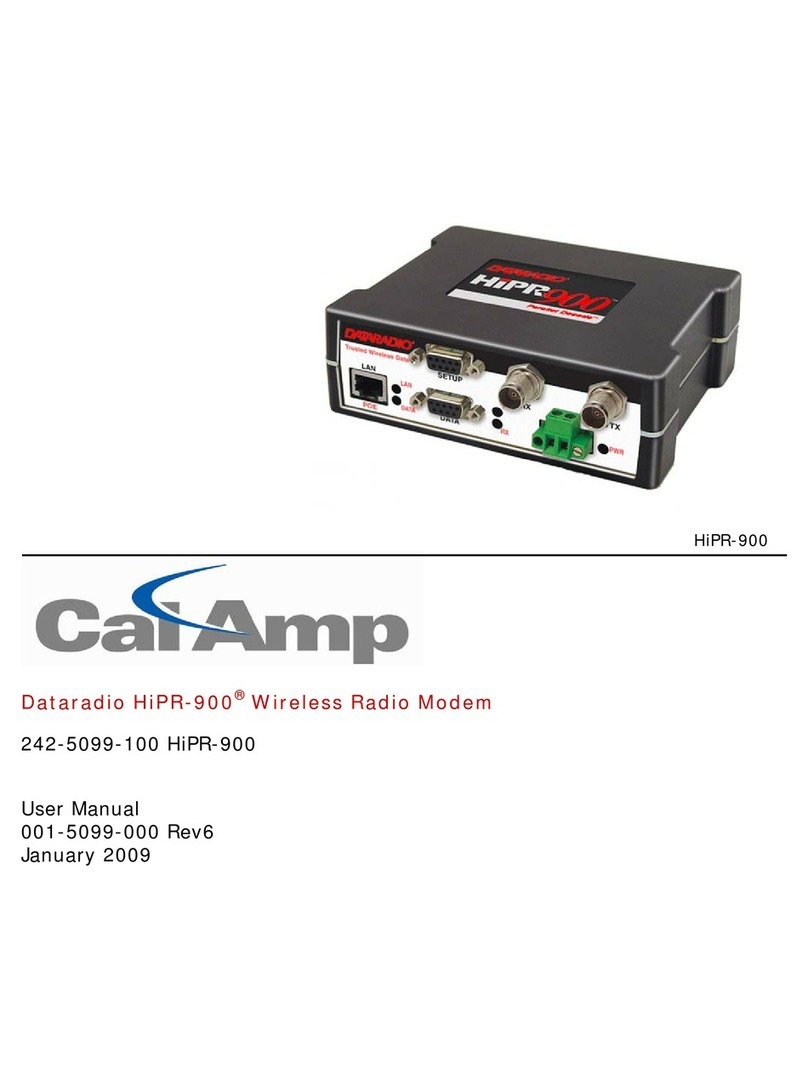
CalAmp Dataradio HiPR-900 User manual

CalAmp

CalAmp Dataradio HiPR-900 User manual

CalAmp SMC-CDMA Series User manual

CalAmp

CalAmp SMC-CDMA Series User manual

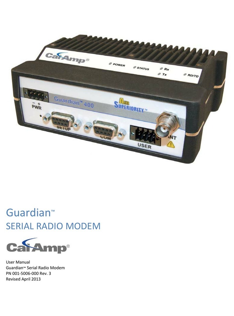
CalAmp GUARDIAN User manual

CalAmp

CalAmp GUARDIAN User manual

CalAmp SMC-GPRS Series User manual

CalAmp

CalAmp SMC-GPRS Series User manual

CalAmp Vanguard 5530 User manual

CalAmp

CalAmp Vanguard 5530 User manual

CalAmp 882?EVDO?XXX User manual

CalAmp

CalAmp 882?EVDO?XXX User manual

CalAmp Integra-Tr User manual

CalAmp

CalAmp Integra-Tr User manual

CalAmp TSLM User manual

CalAmp

CalAmp TSLM User manual

CalAmp 882?GPRS?GEN User manual

CalAmp

CalAmp 882?GPRS?GEN User manual

CalAmp GUARDIAN User manual

CalAmp

CalAmp GUARDIAN User manual

Popular Modem manuals by other brands

Ebyte MA02-XXCX0080 user manual

Ebyte

Ebyte MA02-XXCX0080 user manual

Ubee DDM3521 user guide

Ubee

Ubee DDM3521 user guide

Paradyne COMSPHERE 3910 Installation and operation manual

Paradyne

Paradyne COMSPHERE 3910 Installation and operation manual

Cronyx Qlink-3000/2E1 Installation and operation guide

Cronyx

Cronyx Qlink-3000/2E1 Installation and operation guide

Huawei Mobile WiFi user guide

Huawei

Huawei Mobile WiFi user guide

Arris Touchstone TM602A Quick install guide

Arris

Arris Touchstone TM602A Quick install guide

Lucent Pavilion 9880 user guide

Lucent

Lucent Pavilion 9880 user guide

Telstra TURBO Getting started guide

Telstra

Telstra TURBO Getting started guide

Dataradio T-96SR installation manual

Dataradio

Dataradio T-96SR installation manual

ZyXEL Communications P-664HN-T1 quick start guide

ZyXEL Communications

ZyXEL Communications P-664HN-T1 quick start guide

Motorola M-Series user guide

Motorola

Motorola M-Series user guide

Camatel NetVito 5300 Series quick start guide

Camatel

Camatel NetVito 5300 Series quick start guide

Siemens SE505 user manual

Siemens

Siemens SE505 user manual

Robustel GoRugged M1000 USBV2 user guide

Robustel

Robustel GoRugged M1000 USBV2 user guide

Huawei MT886 user guide

Huawei

Huawei MT886 user guide

Cricket A600 user manual

Cricket

Cricket A600 user manual

Meridian DT-2V2K/2K Installation and operation instructions

Meridian

Meridian DT-2V2K/2K Installation and operation instructions

COX Technicolor CGM4331 Getting started

COX

COX Technicolor CGM4331 Getting started

manuals.online logo
manuals.online logoBrands
  • About & Mission
  • Contact us
  • Privacy Policy
  • Terms and Conditions

Copyright 2025 Manuals.Online. All Rights Reserved.