CALI neonLEDs NLED User manual

Installation Instructions Overview
neonLEDs™NLED
CALIFORNIA ACCENT LIGHTING, INC.
2034 E. Lincoln Ave. #431, Anaheim, CA 92806
ph. 800.921.CALI (2254) or 714.535-7900 \ fx. 714.535.7902
© CALI. All rights reserved. CALI reserves the right to make changes or withdraw specications without prior notice.
1 of 10
• Electric Compound Miter Saw
• 14.4 to 28 Volt Cordless Drill
• Wire Strippers for 22 and 15
gauge wire (24V verison)
• Pliers
• Wire Cutter (24V version)
• Phillips Bits - Sufficient Quantity
• Carbide Masonry Drill Bits -
Sufficient Quantity
• Concrete Tapcon Screws
• Self Drill Metal Screws #8 x 1/2”
- Sufficient Quantity
• Electrical Cords
• Electrical Three Way
• Safety Glasses
• Measuring Tape
• Marker
• Chalk Line
NLED POWER CONNECTOR
LN 1/17/17
NLED-PC-180D NLED-PC-90D
90D housing
(included)
Power Connector
(#NLED-PC-4Amp-120V)
Neon LED
(#NLED)
End Cap
(#NLED-EC)
Mounting Channel
(#NLED-UC)
Mounting Clip
(#NLED-MC)
4” Minimum
Bend Radius
5’
4.3”
1.3”
WARNINGS
• Do not power or light neonLEDs when tightly coiled. Maintain at least
one half inch spacing between parts when lit.
• Do not cover neonLEDs as the covering may cause it to overheat, melt,
and even ignite
• Do not puncture, cut, shorten, or splice neonLEDs
• Do not route neonLEDs through walls, doors, windows, or building
structures
• Do not roll out neonLEDs on rough surfaces or over sharp corners.
• Do not use neonLEDs if damaged, such as, broken outer jacket, loose
connections, or frayed wire insulation. Inspect periodically
• Do not secure neonLEDs with staples, nails, or like means that might
damage the insulation. Secure it by using mounting channel or
mounting clips
• Do not submerge neonLEDs in liquid or install near standing water or
other liquids
• Do not install neonLEDS where it is subject to continuous flexing
• Do not mount neonLEDs inside cabinets, tanks, or enclosures of any
kind without proper ventilation
• Do not run neonLEDs at an operation temperature below -40°C (-40°F)
or above 55°C (131°F)
• Do not replace the attached polarized plug for 120V applications which
contains a safety fuse (120V, 5A)
• Use only standard outdoor extensions cords, such as, SW, STW, STOW,
SJW, SJOW, SJTW, SJTOW, and so on
• Ground Fault Circuit Interruptor (GFCI) protection is required on
circuits or outlets when NeonLEDs is used for outdoor applications
• Surge protector must be set up for electrical power system to avoid
damaging NeonLED lighting system
INSTALLATION TOOLS REQUIRED
Mounting Clip
(#NLED-MC)
Mounting Channel
(#NLED-UC)
Connector Power Cord
(#NLED-PC-180D)
Neon LEDs
(#NLED)
End Cap
(#NLED-EC)
1.06
0.64
END VIEW
1.92
0.82
0.64
0.84
MOUNTING OPTIONS
Mounting Channel
(#NLED-UC)
Mounting Clip
(#NLED-MC)
MOUNTING OPTIONS
Mounting Clip
(#NLED-MC)
Mounting Channel
(#NLED-UC)
Connector Power Cord
(#NLED-PC-180D)
Neon LEDs
(#NLED)
End Cap
(#NLED-EC)
1.06
0.64
END VIEW
1.92
0.82
0.64
0.84
MOUNTING OPTIONS
Mounting Channel
(#NLED-UC)
Mounting Clip
(#NLED-MC)
END VIEW
IMPORTANT VERIFY CORRECT
LUMINAIRE WAS RECEIVED WITH
CORRECT COLOR TEMPERATURE
AND VOLTAGE BEFORE CUTTING
OR INSTALLING. CALI WILL NOT
BE RESPONSIBLE IF INCORRECT
LUMINAIRE IS INSTALLED. DO NOT
CUT WET LOCATION NLED. CONSULT
FACTORY FOR ADDITIONAL DETAILS.

Installation Instructions Overview
neonLEDs™NLED
CALIFORNIA ACCENT LIGHTING, INC.
2034 E. Lincoln Ave. #431, Anaheim, CA 92806
ph. 800.921.CALI (2254) or 714.535-7900 \ fx. 714.535.7902
© CALI. All rights reserved. CALI reserves the right to make changes or withdraw specications without prior notice.
2 of 10
FEATURES
APPLICATIONS Decorative Lighting
VOLTAGE 24V or 120V
LAMP TYPE LEDs
DIMMING 120V: Not Dimmable
24V: 0-10V Dimming (TRA-E)
MAXIMUM RUN 32’ (24V), 150’ (120V)
FINISH White
FEED Power Connector
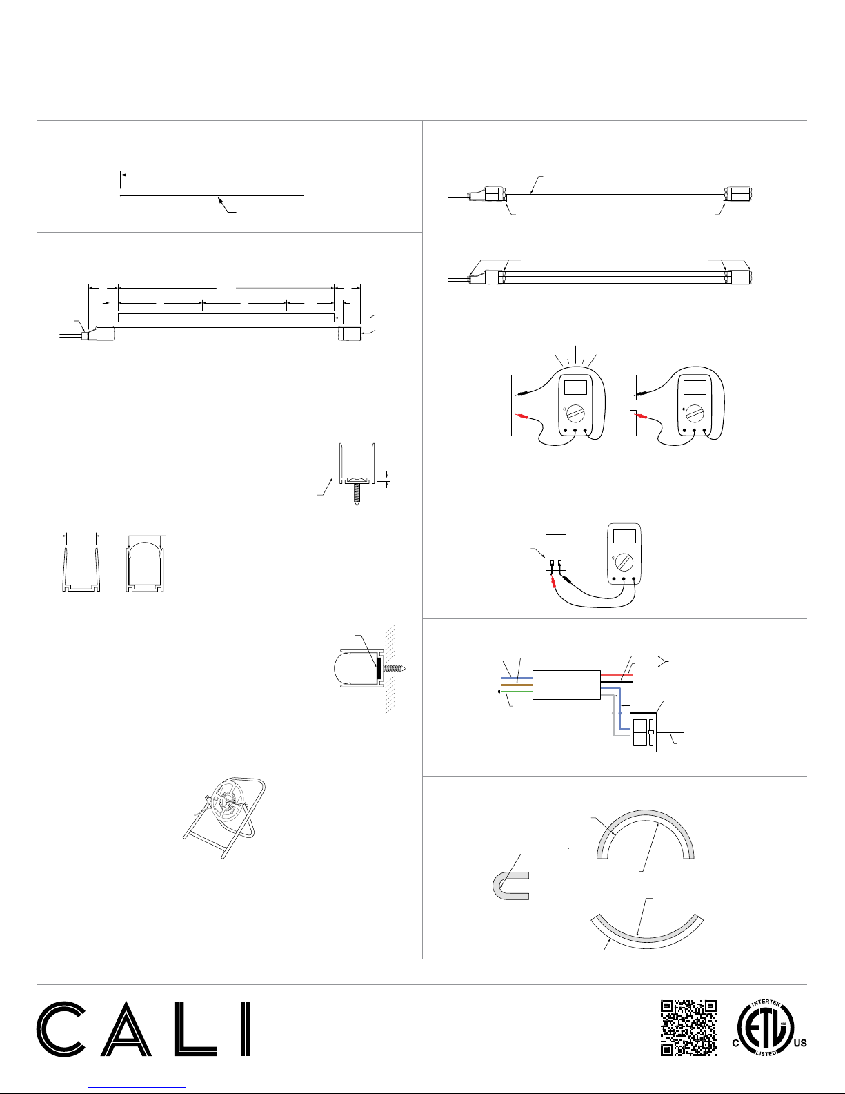
MOUNTING U-Channel or Mounting Clip
LISTING Dry or Wet Location
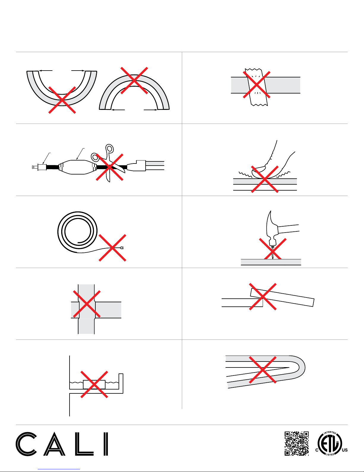
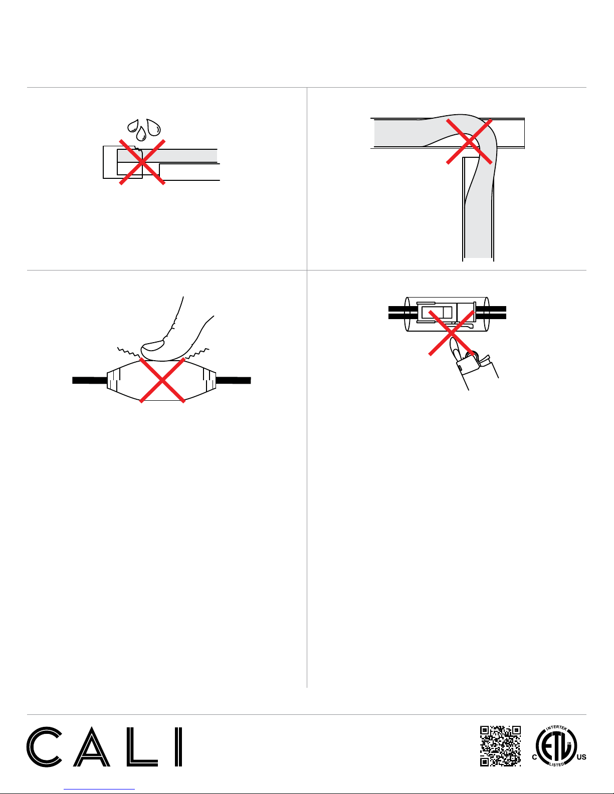
WARNING
When using NLED for any application, basic safety precautions should
always be followed to reduce the risk of fire, electric shock, and
personal injury. NLED must be installed in accordance with the NEC or
CEC as applicable.
• Do not exceed maximum length per circuit. Each maximum run requires
additional power feed from the transformer
• Do not cover NLED as the covering may cause it to overheat, melt,
or ignite.
• Do not install NLED in hazardous locations or closer than 6 inches
from any curtain or similar combustible material.
• Do not install NLED in places where it is subject to continuous
flexing.
• Do not install wet location model in areas where water will collect.
NLED 24V DIMMING PROTOCOL (0-10V)
NLED is available in 120 or 277 volts with a dimmable remote driver. The
remote driver is available with 0-10V dimming capabilities.
The following applies to 0-10V dimming interfaces. A 0-10v fluorescent
dimmer will not dim the LEDs.
Technical Requirements For Control Equipment (0-10V Protocol)
• The output current level of the dimmable driver is controlled by DC voltage
(0-10V) applied to the control terminals (blue and white). The light output of
LEDs is controlled by the amount of output current from the dimmable driver.
• The control device must be capable of sinking a DC current flow from the driver.
The maximum amount under any condition is 500 microamps (uA) per driver.
• The control terminals of the dimmable driver are isolated from the power lines
and are suitable for use as Class 2 wiring. Multiple drivers are desired for use
with same control device, the control terminals may be connected in parallel in a
bus configuration.
• Since the control bus is Class 2 wiring, all control devices that are connected
to the power line must have proper isolation between the power line and the
control terminals/bus.
• The control device, which intends to control more than one dimmable driver,
must be capable of sinking the total current supplied to control bus by the drivers.
• If the control terminals/bus is shorted in any case, the current on the control
terminals/bus will be 500 microamps (uA) per driver maximum.
• If the control terminals are opened, the voltage on the control terminals will them
be 10V ± 0.5 volt. As a result, dimmable driver supplies maximum output current
to LEDs under this condition.
• The driver is intended for use with control voltages between 0 and 10 VDC. The
control equipment must not impose a voltage greater than 11 V peak maximum
on the driver control terminals.
• Order transformer with TRA-E prefix.
(TRA-E) 0-10V Dimming

Installation Instructions
neonLEDs™NLED
CALIFORNIA ACCENT LIGHTING, INC.
2034 E. Lincoln Ave. #431, Anaheim, CA 92806
ph. 800.921.CALI (2254) or 714.535-7900 \ fx. 714.535.7902
© CALI. All rights reserved. CALI reserves the right to make changes or withdraw specications without prior notice.
3 of 10
Product Care
Do not bend neonLED to a diameter of less than the following:
Concave Convex
Channel must be on flat, flush surface
Do not cut power cord.
The power cord contains a 5A safety fuse and rectifier.
Do not connect neonLED to power source while spooled or coiled
Do not overlap neonLED at any location
Do not penetrate neonLED with any foreign object
Do not apply excessive pressure to surface of neonLED
Do not cover neonLED with any material
<12”
<8”
<12”
<8”
<12”
<8”
<12”
<8”
<12”
<8”
<12”
<8”
<12”
<8”
Do not overlap U-channel in any way
Do not install neonLED in a zig zag fashion
<12”
<8”
<12”
<8”
Do not install wet location in outdoor cove without proper drainage
<12”
<8”
<12”
<8”
Rectifier
Safety fuse

Installation Instructions
neonLEDs™NLED
CALIFORNIA ACCENT LIGHTING, INC.
2034 E. Lincoln Ave. #431, Anaheim, CA 92806
ph. 800.921.CALI (2254) or 714.535-7900 \ fx. 714.535.7902
© CALI. All rights reserved. CALI reserves the right to make changes or withdraw specications without prior notice.
4 of 10
Product Care
Do not install neonLED with damaged seals
or without shrink tube in wet location
Do not cross U-channels and twist neonLED to overlap
Do not apply excessive pressure to rectifier
<12”
<8”
<12”
<8”
<12”
<8”
Do not use a lighter to heat shrink tube
2” 2”
<1.5”
<1.5”
(<38.1mm)
(<38.1mm)
White (-)
Red (+)
Black (-)
Blue
(Neutral)
Brown
(Hot)
Line
Green
(Ground)
Optional Dimmer
(not included)
Blue (+)
TRA
6”
4”
<1.5”
<1.5”

Installation Instructions
neonLEDs™NLED
CALIFORNIA ACCENT LIGHTING, INC.
2034 E. Lincoln Ave. #431, Anaheim, CA 92806
ph. 800.921.CALI (2254) or 714.535-7900 \ fx. 714.535.7902
© CALI. All rights reserved. CALI reserves the right to make changes or withdraw specications without prior notice.
5 of 10
Application Guidelines
One person on one end applies pressure
to neonLED, securing it into U-channel
Leave a 0.5” gap between end of U-channel and
beginning of sealed power cord and end cap
NEONLED REQUIRES A TEAM EFFORT TO ENSURE SECURE AND CORRECT INSTALLATION
Another person unreels NLED from
spool, holding neonLED at 45° angle
45°
Push NLED firmly
into U-channel
Feed from wire puller stand
U-Channel

Installation Instructions
neonLEDs™NLED
CALIFORNIA ACCENT LIGHTING, INC.
2034 E. Lincoln Ave. #431, Anaheim, CA 92806
ph. 800.921.CALI (2254) or 714.535-7900 \ fx. 714.535.7902
© CALI. All rights reserved. CALI reserves the right to make changes or withdraw specications without prior notice.
6 of 10
Power Cord
5’ 5’
5’
5’
White (+)
Black (-)
3.3”
3.3”
White (+)
Black (-)
18”
37”
18”
37”
1.25”
1.25”
3.3”
1.25”
5’ 5’
5’
5’
White (+)
Black (-)
3.3”
3.3”
White (+)
Black (-)
18”
37”
18”
37”
1.25”
1.25”
3.3”
1.25”
5’
5’
5’
5’
White (+)
Black (-)
3.3”
3.3”
White (+)
Black (-)
18”
37”
18”
37”
1.25”
1.25”
3.3”
1.25”
5’ 5’
5’
5’
White (+)
Black (-)
3.3”
3.3”
White (+)
Black (-)
18”
37”
18”
37”
1.25”
1.25”
3.3”
1.25”
NLED-PC-180D-120V-4A-5’
NLED-PC-180D-120V-1.6A-5’
NLED-PC-180D-24V-5’ NLED-PC-90D-24V-5’
NLED-PC-90D-120V-1.6A-5’
NLED-PC-90D-120V-4A-5’
Maximum neonLED run with
4 Amp power connector: 150’
5’
5’
5’
5’
White (+)
Black (-)
3.3”
3.3”
White (+)
Black (-)
18”
37”
18”
37”
1.25”
1.25”
3.3”
1.25”
Rectifier measures 4.3” x 1.3”
Maximum neonLED run with
1.6 Amp power connector: 60’
Maximum neonLED run with
4 Amp power connector: 150’
Maximum neonLED run with
1.6 Amp power connector: 60’
Maximum 24V neonLED run: 32’
5’ 5’
5’
5’
White (+)
Black (-)
3.3”
3.3”
White (+)
Black (-)
18”
37”
18”
37”
1.25”
1.25”
3.3”
1.25”
Rectifier measures 3.7” x .94”
Rectifier measures
4.3” x 1.3”
Rectifier measures
3.7” x .94”

Installation Instructions
neonLEDs™
CALIFORNIA ACCENT LIGHTING, INC.
2034 E. Lincoln Ave. #431, Anaheim, CA 92806
ph. 800.921.CALI (2254) or 714.535-7900 \ fx. 714.535.7902
© CALI. All rights reserved. CALI reserves the right to make changes or withdraw specications without prior notice.
7 of 10
Step by Step (24V)
NLED-24V
1. Measure area where neonLEDs will be installed.
RECOMMENDATION: Use chalk line to ensure a straight installation.
4. Mount NLED into channel, leaving a one half inch gap between
the channel and sealed power cord and sealed end cap.
3. Install NLED into channel. Use a wire puller stand to ensure secure
and correct installation.
2. Cut U-Channel as necessary and secure with screws (by others), then
mount NLED to U-Channel.
2b. Screw head must be flush to Line A.
RECOMMENDATION: Use pan head screws with
head thickness less than .1”.
4b. After installing, apply silicone on both ends for a complete seal.
Check the U-Channel opening.
2c. Apply double stick tape to hold NLED securely in U-Channel for
applications facing outward or downward.
RECOMMENDATION:
- 3M 4008 double stick tape 3/8” width (not included).
- Leave open spaces where screws are present.
NOTE:
- Do not install power lead or end cap into U-Channel.
- Do not interfere with silicone or shrink tube while installing NLED into U-Channel.
- Cut U-Channel if it interferes with sealed shrink tube.
- When installing, do not pull on power leads or end caps. Pulling on NLED and extending
flexible lights will cause the lights to expand during installation, then contract,
compromising the seal.
PUSH PUSH
PUSHPUSH
PUSH PUSH
PUSH PUSH
PUSH PUSH
Chalk line
20’
9/16”
or
smaller
Friction keeps
NLED from falling
Double stick tape
Apply silicone
(not included)
Male pin
connector
180° 120V connector
power cord
Apply silicone
(not included)
End cap
Shrink tube
NLED
.95”
Line A
3” 3”
.5”.5”
19’6”
8’8’ 3’6”
U-Channel
Power cord
End cap
Lateral bend
4” minimum radius
Convex bend 4”
minimum radius
Bottom of
extrusion
Bottom of
extrusion
Concave bend 6”
minimum radius
Apply silicone Apply silicone
Cutting line
Top of
extrusion
LLED
0.64”
0.84”
1.92”
0.84”
0.5” gap
U-channel
0.5” gap
5. Conduct continuity test.
6. Set voltmeter to DC voltage, then test power source before connecting.
8. Minimum bend radius.
7. Connect power source to power connector.
If a conductive
path is formed
between positive
and negative wire,
the multimeter will
beep. You need to
trouble shoot to
find the short.
If there is no
conductive path, the
multimeter will not
beep.
Troubleshoot Good
VAC
OFF VDC
ACOM
Ω
VΩ
VAC
OFF VDC
ACOM
Ω
VΩ
+ -
DCA
OFF DCV
ACOM
Ω
VΩ
DCA
OFF DCV
ACOM
Ω
VΩ
VAC
OFF VDC
ACOM
Ω
VΩ
VAC
OFF VDC
ACOM
Ω
VΩ
+ -
DCA
OFF DCV
ACOM
Ω
VΩ
DCA
OFF DCV
ACOM
Ω
VΩ
Confirm the correct
voltage, depending on
the light strip.
TRA power
source
DCV
VAC
OFF VDC
ACOM
Ω
VΩ
VAC
OFF VDC
ACOM
Ω
VΩ
+ -
DCA
OFF DCV
ACOM
Ω
VΩ
DCA
OFF DCV
ACOM
Ω
VΩ
Wire puller stand
2” 2”
<1.5”
<1.5”
(<38.1mm)
(<38.1mm)
White (-)
Red (+)
Black (-)
Blue
(Neutral)
Brown
(Hot)
Line
Green
(Ground)
Optional Dimmer
(not included)
Blue (+)
TRA
6”
4”
<1.5”
<1.5”
White (-)
24VDC
Red (+)
Black (-)
Blue
(Neutral)
Brown
(Hot)
Line
Green
(Ground)
Optional Dimmer
(not included)
Blue (+)
TRAXXX-E/UNV/24VDC/-10V
(Refer to page 4 for additional details)
(Refer to page 6 for additional details)

Installation Instructions
neonLEDs™
CALIFORNIA ACCENT LIGHTING, INC.
2034 E. Lincoln Ave. #431, Anaheim, CA 92806
ph. 800.921.CALI (2254) or 714.535-7900 \ fx. 714.535.7902
© CALI. All rights reserved. CALI reserves the right to make changes or withdraw specications without prior notice.
8 of 10
NLED-24V
Troubleshooting (24V)
TROUBLESHOOT
• Do not reset breaker multiple times.
• If the unit is overloaded the breaker will trip shutting off the
transformer and lights.
• If the breaker reset button has been held down by hand or any type
of pressure (example: duct tape), or if the breaker has been reset
multiple times without trouble shooting, the unit will:
- Burn the transformer bobbin
- Burn the primary or secondary wires due to high amperage caused
by overload and/ or short circuit in line which will not allow the
breaker to reset
- Damage the lighting
1. Turn off power before beginning. Check for any twisting or damage to
the circuit in the neonLED. If there is excessive damage and
circuit is broken, the lightstrip must be replaced.
2. Check for metal particles or other foreign objects causing the short.
3. Check if cut is clean and not frayed, causing positive and negative
copper nodes to touch.
4. Ensure the run is not too long and overlapping.
5. Ensure copper nodes are not making contact with aluminum extrusion.
6. Check for water inside end cap or power connector. Water needs to be
removed before connecting to power.
7. After above items have been checked, refer to continuity test:
(Steps 5 - 7 on page 5).
White (-)
24VDC
Red (+)
Black (-)
Blue
(Neutral)
Brown
(Hot)
Line
Green
(Ground)
Optional Dimmer
(not included)
Blue (+)
Frayed end
White (-)
24VDC
Red (+)
Black (-)
Blue
(Neutral)
Brown
(Hot)
Line
Green
(Ground)
Optional Dimmer
(not included)
Blue (+)
Metal flakes
Foreign object
White (-)
24VDC
Red (+)
Black (-)
Blue
(Neutral)
Brown
(Hot)
Line
Green
(Ground)
Optional Dimmer
(not included)
Blue (+)
Metal flakes
Foreign object
White (-)
24VDC
Red (+)
Black (-)
Blue
(Neutral)
Brown
(Hot)
Line
Green
(Ground)
Optional Dimmer
(not included)
Blue (+)
Damaged lightstripTorn lightstrip
White (-)
24VDC
Red (+)
Black (-)
Blue
(Neutral)
Brown
(Hot)
Line
Green
(Ground)
Optional Dimmer
(not included)
Blue (+)
Twisted lightstrip
White (-)
24VDC
Red (+)
Black (-)
Blue
(Neutral)
Brown
(Hot)
Line
Green
(Ground)
Optional Dimmer
(not included)
Blue (+)
Excess lightstrip overlapping and
held down with tape or other force
White (-)
24VDC
Red (+)
Black (-)
Blue
(Neutral)
Brown
(Hot)
Line
Green
(Ground)
Optional Dimmer
(not included)
Blue (+)
Copper nodes touching extrusion
White (-)
24VDC
Red (+)
Black (-)
Blue
(Neutral)
Brown
(Hot)
Line
Green
(Ground)
Optional Dimmer
(not included)
Blue (+)
Water inside power connector
Compromised seal
White (-)
24VDC
Red (+)
Black (-)
Blue
(Neutral)
Brown
(Hot)
Line
Green
(Ground)
Optional Dimmer
(not included)
Blue (+)
Water inside power connector
Compromised seal
Water inside end cap
White (-)
24VDC
Red (+)
Black (-)
Blue
(Neutral)
Brown
(Hot)
Line
Green
(Ground)
Optional Dimmer
(not included)
Blue (+)
Compromised seal
Water inside end cap
White (-)
24VDC
Red (+)
Black (-)
Blue
(Neutral)
Brown
(Hot)
Line
Green
(Ground)
Optional Dimmer
(not included)
Blue (+)
Compromised seal

Installation Instructions
neonLEDs™
CALIFORNIA ACCENT LIGHTING, INC.
2034 E. Lincoln Ave. #431, Anaheim, CA 92806
ph. 800.921.CALI (2254) or 714.535-7900 \ fx. 714.535.7902
© CALI. All rights reserved. CALI reserves the right to make changes or withdraw specications without prior notice.
9 of 10
Step by Step (120V)
NLED-120V
1. Measure area where neonLEDs will be installed.
RECOMMENDATION: Use chalk line to ensure a straight installation.
4. Mount NLED into channel, leaving a one half inch gap between
the channel and sealed power cord and sealed end cap.
3. Install NLED into channel. Use a wire puller stand to ensure secure
and correct installation.
2. Cut U-Channel as necessary and secure with screws (by others), then
mount NLED to U-Channel.
2b. Screw head must be flush to Line A.
RECOMMENDATION: Use pan head screws with
head thickness less than .1”.
4b. After installing, apply silicone on both ends for a complete seal.
Check the U-Channel opening.
2c. Apply double stick tape to hold NLED securely in U-Channel for
applications facing outward or downward.
RECOMMENDATION:
- 3M 4008 double stick tape 3/8” width (not included).
- Leave open spaces where screws are present.
NOTE:
- Do not install power lead or end cap into U-Channel.
- Do not interfere with silicone or shrink tube while installing NLED into U-Channel.
- Cut U-Channel if it interferes with sealed shrink tube.
- When installing, do not pull on power leads or end caps. Pulling on NLED and extending
flexible lights will cause the lights to expand during installation, then contract,
compromising the seal.
PUSH PUSH
PUSHPUSH
PUSH PUSH
PUSH PUSH
PUSH PUSH
Chalk line
20’
9/16”
or
smaller
Friction keeps
NLED from falling
Double stick tape
Apply silicone
(not included)
Male pin
connector
180° 120V connector
power cord
Apply silicone
(not included)
End cap
Shrink tube
NLED
.95”
Line A
3” 3”
.5”.5”
19’6”
8’8’ 3’6”
U-Channel
Power cord
End cap
Lateral bend
4” minimum radius
Convex bend 4”
minimum radius
Bottom of
extrusion
Bottom of
extrusion
Concave bend 6”
minimum radius
Apply silicone Apply silicone
Cutting line
Top of
extrusion
LLED
0.64”
0.84”
1.92”
0.84”
0.5” gap
U-channel
0.5” gap
9/16”
or
smaller
Friction keeps
NLED from falling
Double stick tape
Apply silicone
(not included)
Male pin
connector
180° 120V connector
power cord
Apply silicone
(not included)
End cap
Shrink tube
NLED
.95”
Line A
3” 3”
.5”.5”
19’6”
8’8’ 3’6”
U-Channel
Power cord
End cap
Lateral bend
4” minimum radius
Convex bend 4”
minimum radius
Bottom of
extrusion
Bottom of
extrusion
Concave bend 6”
minimum radius
Apply silicone Apply silicone
Cutting line
Top of
extrusion
LLED
0.64”
0.84”
1.92”
0.84”
0.5” gap
U-channel
0.5” gap
9/16”
or
smaller
Friction keeps
NLED from falling
Double stick tape
Apply silicone
(not included)
Male pin
connector
180° 120V connector
power cord
Apply silicone
(not included)
End cap
Shrink tube
NLED
.95”
Line A
3” 3”
.5”.5”
19’6”
8’8’ 3’6”
U-Channel
Power cord
End cap
Lateral bend
4” minimum radius
Convex bend 4”
minimum radius
Bottom of
extrusion
Bottom of
extrusion
Concave bend 6”
minimum radius
Apply silicone Apply silicone
Cutting line
Top of
extrusion
LLED
0.64”
0.84”
1.92”
0.84”
0.5” gap
U-channel
0.5” gap
9/16”
or
smaller
Friction keeps
NLED from falling
Double stick tape
Apply silicone
(not included)
Male pin
connector
180° 120V connector
power cord
Apply silicone
(not included)
End cap
Shrink tube
NLED
.95”
Line A
3” 3”
.5”.5”
19’6”
8’8’ 3’6”
U-Channel
Power cord
End cap
Lateral bend
4” minimum radius
Convex bend 4”
minimum radius
Bottom of
extrusion
Bottom of
extrusion
Concave bend 6”
minimum radius
Apply silicone Apply silicone
Cutting line
Top of
extrusion
LLED
0.64”
0.84”
1.92”
0.84”
0.5” gap
U-channel
0.5” gap
9/16”
or
smaller
Friction keeps
NLED from falling
Double stick tape
Apply silicone
(not included)
Male pin
connector
180° 120V connector
power cord
Apply silicone
(not included)
End cap
Shrink tube
NLED
.95”
Line A
3” 3”
.5”.5”
19’6”
8’8’ 3’6”
U-Channel
Power cord
End cap
Lateral bend
4” minimum radius
Convex bend 4”
minimum radius
Bottom of
extrusion
Bottom of
extrusion
Concave bend 6”
minimum radius
Apply silicone Apply silicone
Cutting line
Top of
extrusion
LLED
0.64”
0.84”
1.92”
0.84”
0.5” gap
U-channel
0.5” gap
9/16”
or
smaller
Friction keeps
NLED from falling
Double stick tape
Apply silicone
(not included)
Male pin
connector
180° 120V connector
power cord
Apply silicone
(not included)
End cap
Shrink tube
NLED
.95”
Line A
3” 3”
.5”.5”
19’6”
8’8’ 3’6”
U-Channel
Power cord
End cap
Lateral bend
4” minimum radius
Convex bend 4”
minimum radius
Bottom of
extrusion
Bottom of
extrusion
Concave bend 6”
minimum radius
Apply silicone Apply silicone
Cutting line
Top of
extrusion
LLED
0.64”
0.84”
1.92”
0.84”
0.5” gap
U-channel
0.5” gap
9/16”
or
smaller
Friction keeps
NLED from falling
Double stick tape
Apply silicone
(not included)
Male pin
connector
180° 120V connector
power cord
Apply silicone
(not included)
End cap
Shrink tube
NLED
.95”
Line A
3” 3”
.5”.5”
19’6”
8’8’ 3’6”
U-Channel
Power cord
End cap
Lateral bend
4” minimum radius
Convex bend 4”
minimum radius
Bottom of
extrusion
Bottom of
extrusion
Concave bend 6”
minimum radius
Apply silicone Apply silicone
Cutting line
Top of
extrusion
LLED
0.64”
0.84”
1.92”
0.84”
0.5” gap
U-channel
0.5” gap
5. Conduct continuity test.
6. Set voltmeter to AC voltage, then test power source before connecting.
8. Minimum bend radius.
7. Connect polarized plug which contains a safety fuse (120V, 5A).
If a conductive
path is formed
between hot and
neutral wires on
power plug, the
multimeter will
beep. You need to
trouble shoot to
find the short.
If there is no
conductive path
between hot and
neutral wires, the
multimeter will
not beep.
Troubleshoot Good
VAC
OFF VDC
ACOM
Ω
VΩ
VAC
OFF VDC
ACOM
Ω
VΩ
+ -
DCA
OFF DCV
ACOM
Ω
VΩ
DCA
OFF DCV
ACOM
Ω
VΩ
VAC
OFF VDC
ACOM
Ω
VΩ
VAC
OFF VDC
ACOM
Ω
VΩ
+ -
DCA
OFF DCV
ACOM
Ω
VΩ
DCA
OFF DCV
ACOM
Ω
VΩ
Confirm the correct
voltage 120VAC
Power source
ACV
VAC
OFF VDC
ACOM
Ω
VΩ
VAC
OFF VDC
ACOM
Ω
VΩ
+ -
DCA
OFF DCV
ACOM
Ω
VΩ
DCA
OFF DCV
ACOM
Ω
VΩ
White (-)
24VDC
Red (+)
Black (-)
Blue
(Neutral)
Brown
(Hot)
Line
Green
(Ground)
Optional Dimmer
(not included)
Blue (+)
Leave clearance
Mount rectifier
outside of GFCI
GFCI not included
Wire puller stand
2” 2”
<1.5”
<1.5”
(<38.1mm)
(<38.1mm)
White (-)
Red (+)
Black (-)
Blue
(Neutral)
Brown
(Hot)
Line
Green
(Ground)
Optional Dimmer
(not included)
Blue (+)
TRA
6”
4”
<1.5”
<1.5”
(Refer to page 8 for additional details)
(Refer to page 4 for additional details)
GFCI

Installation Instructions
neonLEDs™
CALIFORNIA ACCENT LIGHTING, INC.
2034 E. Lincoln Ave. #431, Anaheim, CA 92806
ph. 800.921.CALI (2254) or 714.535-7900 \ fx. 714.535.7902
© CALI. All rights reserved. CALI reserves the right to make changes or withdraw specications without prior notice.
10 of 10
Troubleshooting (120V)
NLED-120V
TROUBLESHOOT
• Do not reset breaker or GFCI multiple times.
• If the unit is overloaded the breaker will trip shutting off the lights.
• If the breaker or GFCI reset button has been held down by hand or
any type of pressure (example: duct tape), or if the breaker has been
reset multiple times without trouble shooting, the unit will:
- Burn the primary or secondary wires due to high amperage caused
by overload and/ or short circuit in line which will not allow the
breaker to reset
- Damage the lighting
1. Turn off power before beginning. Check for any twisting or damage to
the circuit in the LED lightstrip. If there is excessive damage and
circuit is broken, the lightstrip must be replaced.
2. Check for metal particles or other foreign objects causing the short.
3. Check if cut is clean and not frayed, causing positive and negative
copper nodes to touch.
4. Ensure the run is not too long and overlapping.
5. Ensure copper nodes are not making contact with aluminum extrusion.
6. Check for water inside end cap or power connector. Water needs to be
removed before connecting to power.
7. After above steps have been checked, replace 5A fuse, then follow
steps 5 - 7 on page 7.
White (-)
24VDC
Red (+)
Black (-)
Blue
(Neutral)
Brown
(Hot)
Line
Green
(Ground)
Optional Dimmer
(not included)
Blue (+)
Frayed end
White (-)
24VDC
Red (+)
Black (-)
Blue
(Neutral)
Brown
(Hot)
Line
Green
(Ground)
Optional Dimmer
(not included)
Blue (+)
Metal flakes
Foreign object
White (-)
24VDC
Red (+)
Black (-)
Blue
(Neutral)
Brown
(Hot)
Line
Green
(Ground)
Optional Dimmer
(not included)
Blue (+)
Metal flakes
Foreign object
White (-)
24VDC
Red (+)
Black (-)
Blue
(Neutral)
Brown
(Hot)
Line
Green
(Ground)
Optional Dimmer
(not included)
Blue (+)
Damaged lightstripTorn lightstrip
White (-)
24VDC
Red (+)
Black (-)
Blue
(Neutral)
Brown
(Hot)
Line
Green
(Ground)
Optional Dimmer
(not included)
Blue (+)
Twisted lightstrip
White (-)
24VDC
Red (+)
Black (-)
Blue
(Neutral)
Brown
(Hot)
Line
Green
(Ground)
Optional Dimmer
(not included)
Blue (+)
Excess lightstrip overlapping and
held down with tape or other force
White (-)
24VDC
Red (+)
Black (-)
Blue
(Neutral)
Brown
(Hot)
Line
Green
(Ground)
Optional Dimmer
(not included)
Blue (+)
Copper nodes touching extrusion
White (-)
24VDC
Red (+)
Black (-)
Blue
(Neutral)
Brown
(Hot)
Line
Green
(Ground)
Optional Dimmer
(not included)
Blue (+)
Water inside power connector
Compromised seal
White (-)
24VDC
Red (+)
Black (-)
Blue
(Neutral)
Brown
(Hot)
Line
Green
(Ground)
Optional Dimmer
(not included)
Blue (+)
Water inside power connector
Compromised seal
Water inside end cap
White (-)
24VDC
Red (+)
Black (-)
Blue
(Neutral)
Brown
(Hot)
Line
Green
(Ground)
Optional Dimmer
(not included)
Blue (+)
Compromised seal
Water inside end cap
White (-)
24VDC
Red (+)
Black (-)
Blue
(Neutral)
Brown
(Hot)
Line
Green
(Ground)
Optional Dimmer
(not included)
Blue (+)
Compromised seal
White (-)
24VDC
Red (+)
Black (-)
Blue
(Neutral)
Brown
(Hot)
Line
Green
(Ground)
Optional Dimmer
(not included)
Blue (+)
Remove screw at end of
power plug to replace fuse.

Installation Instructions
neonLEDs™NLED
CALIFORNIA ACCENT LIGHTING, INC.
2034 E. Lincoln Ave. #431, Anaheim, CA 92806
ph. 800.921.CALI (2254) or 714.535-7900 \ fx. 714.535.7902
© CALI. All rights reserved. CALI reserves the right to make changes or withdraw specications without prior notice.
11 of 10
Transformer
SECONDARY
VOLTAGE
WIRE
SIZE
40
VA
80
VA
120
VA
160
VA
200
VA
240
VA
260
VA
280
VA
300
VA
320
VA
12V
24V
14GA 75’ 37’ 25’ 19’ 15’ 12’ 12’ 11’ 10’ 9’
12GA 118’ 59’ 39’ 30’ 24’ 18’ 18’ 17’ 16’ 15’
10GA 188’ 94’ 63’ 47’ 38’ 29’ 29’ 27’ 25’ 24’
8GA 299’ 149’ 100’ 75’ 60’ 46’ 46’ 43’ 40’ 37’
PERCENT LIGHT OUTPUT TABLE
WIRE
SIZE
DIST.
FROM
TRANS.
50 VA 100 VA 150 VA 200 VA 250 VA 300 VA
12GA 20’ 99 98 97 95 94 89
40’ 98 95 89 83 80 79
60’ 97 89 82 82 72 70
80’ 95 83 79 71 63 56
100 90 80 73 63 54 52
160’ 83 71 56 45 35 26
10GA 20’ 99 99 98 97 96 92
40’ 99 97 92 91 88 84
60’ 98 92 89 84 81 80
80’ 98 91 84 80 78 73
100’ 97 88 81 78 72 65
160’ 90 80 73 63 55 51
200’ 88 78 65 55 45 40
8GA 20’ 99 99 99 99 98 98
40’ 99 98 98 98 97 97
60’ 99 98 98 97 89 88
80’ 99 99 97 97 88 83
100’ 98 97 89 83 81 79
160’ 97 88 81 78 72 65
200’ 92 83 80 72 64 56
400’ 83 72 57 45 39 27
ONLY LOAD TRANSFORMERS TO 80%
WATTS (VA) PER CIRCUIT
MAXIMUM WIRE LENGTH TABLE TO PREVENT VOLTAGE DROP

Installation Instructions Overview
neonLEDs™NLED
CALIFORNIA ACCENT LIGHTING, INC.
2034 E. Lincoln Ave. #431, Anaheim, CA 92806
ph. 800.921.CALI (2254) or 714.535-7900 \ fx. 714.535.7902
© CALI. All rights reserved. CALI reserves the right to make changes or withdraw specications without prior notice.
12 of 10
CLEANING MATERIALS NLED
The use of solvents and/or cleaners which are not compatible with polycarbonate will result in the softening, crazing, and/or cracking of the
plastic part. This is especially true of polycarbonate lamps and mounting bases which may be under stress in their normal applications.
COMPATIBLE WITH POLYCARBONATE:
• Mild soap and water • Mineral Spirits • Isobutyl alcohol
• VM and P Naphtha • Varsol No.2 • Mexane
• Freone TF and TE-35 • Ethanol • Dirtex
• 2% Sol. Reg. Joy • 10% Sol Bon Ami • White Kerosene
• Methyl alcohol • Heptane • Petroleum Ether/65 degrees C
• Isopropyl alcohol • Lacryl PCL-2035 polycarbonate cleaner
NOT COMPATIABLE WITH POLYCARBONATE
• Trichlor • Gasoline • ll Liquid Detergents
• Acetone • Carbon Tetrachloride • Pink Lux (Phosphate free)
• Triclene • Chlorinated Hydrocarbons •#1 & #3 denatured alcohol
• Methyl Ethyl Keytone (MEK) • Texize-8006, 8129, 8758 • MIBK
• Liquid Cleaner – 8211 • Toluol • Agitene
• Benzol • Ajax • Kleenol Plastics
• Lysol • Stanisol Naphtha • Oils
• Lemon Joy (phosphate free) • Diversol • Lestoil
Table of contents
Other CALI Lighting Equipment manuals