Calira BC 722 Instruction manual

B51 080992 00
40A
16
20
24
18
22
26
17
21
25
19
23
27
1
5
3
2
6
4
G
3
3
2
2pol. 5pol.
7pol.
5
Anschlußplan
25A
10mm² RT
4mm² RT
4mm² GN/GE
12V-Verbraucher 1 (10A)
12V-Verbraucher 2 (10A)
12V-Verbraucher 3 (15A)
Sofortlicht (10)
Wasserpumpe (5A)
0,75mm² BR
0,75mm² RT
10mm² RT
4mm² BL
H
In die Tanks Löcher mit 9,5-
10,0mm bohren.
Bohrungen von außen, und möglichst
auch von innen, entgraten
9,5-10mm
Meßfühler zusammensetzen,
Schrauben dabei mit Dicht-
masse oder elastischem
Kleber einsetzen, Schrauben
zunächst nur lose von Hand
anziehen
-Meßfühler in die Tankbohrung
einsetzen
-Kabelfarben beachten- und mit
Schraubendreher fest anziehen.
Der Rand der Gummidichtung
wird dabei gegen die Außenwand
des Tanks gepreßt. Innen bildet
sich eine Gummiwulst, welche die
Bohrung zuverlässig abdichtet
BC 722 - EVS 17/16-DS/IU Art.-Nr.H08 012 0722 00
I
II
III
Bord Control 722
1/1
0
1/2
3/4
13V
<11.5V
+
ON
(RESET)
I
Made in Germany
EVS 17/16-DS/IU
Kühlschrank (15A)
230V/50Hz
230V Verteilung
230V Eingang
230V Ausgang
Potential-
ausgleich
Stecker
4-polig
Stecker 6-polig
Stecker
12-polig
Stiftgehäuse
7-polig
+ Ladestrom
D+Lichtmaschine
B+Meßleitung/Test
+Versorgen
minus
Kabelstrang EVS-BC
Batterie 12V
Batterie 12V
(starten)
(versorgen)
40A
16mm²
2A
Tank I
Tank II
(Frischwasser)
(Abwasser)
Kuppiungs-
stecker
orange
weiß
X=min.50mm
3/4H
2A
7
7
9
8
10
7
9
8
10
CALIRA Electronic GmbH & Co. KG Lerchenfeldstraße 9 87600 Kaufbeuren-Neugablonz

B51 080993 00
40A
16
20
24
18
22
26
17
21
25
19
23
27
1
5
3
2
6
4
G
3
3
2
2pol. 5pol.
7pol.
5
Connection diagram
25A
10mm² RD
0,75mm² RD
0,75mm² BR
4mm² RD
4mm² GN/YE
12V-Consumer 1 (10A)
230V Distribution
12V-Consumer 2 (10A)
12V-Consumer 3 (15A)
Continuous power (10A)
Water pump (5A)
Refrigerator (15A)
10mm² RD
4mm² BU
H
Drill holes into the tanks with 9,5-
10,0mm diameter.
Burr the holes from both sides.
9,5-10mm
Compose the sensor, insert the screw
with sealing compound and fasten
screws first only by hand.
Insert the sensor into the hole in the
tank and fasten it with a srew driver.
Note the wire colours. The edge of the
rubber gasket is pressed against the
outer surface of the tank. Inside the
tank it forms a rubber fold, which seals
up the hole sure.
BC 722 - EVS 17/16-DS/IU Art.-Nr.H08 012 0722 00
I
II
III
Bord Control 722
1/1
0
1/2
3/4
13V
<11.5V
+
ON
(RESET)
I
Made in Germany
CALIRA Electronic GmbH & Co. KG Lerchenfeldstraße 9 87600 Kaufbeuren-Neugablonz
Tank II Tank I
(Waste water) (Fresh water)
Connection
plug
Battery 12V Battery 12V
(supply) (start) Cable EVS - BC
Connector
7pole
Plug
12pole
Plug
6pole
Plug 6pole
Plug
4pole
230V Output
Potential
equalization
230V Input
+Supply
D Generator+
B+ Measuring cable/Test
minus
+Charging current
Fuses must be assembled near
to the +poles of the batteries
and D+ of the generator
orange
white
230V/50Hz
EVS 17/16-DS/IU
Made in Germany
40A
2A
2A
16mm²
7
3/4H
X=min.50mm
7
9
8
10
7
9
8
10

1
7 9
246
810
35
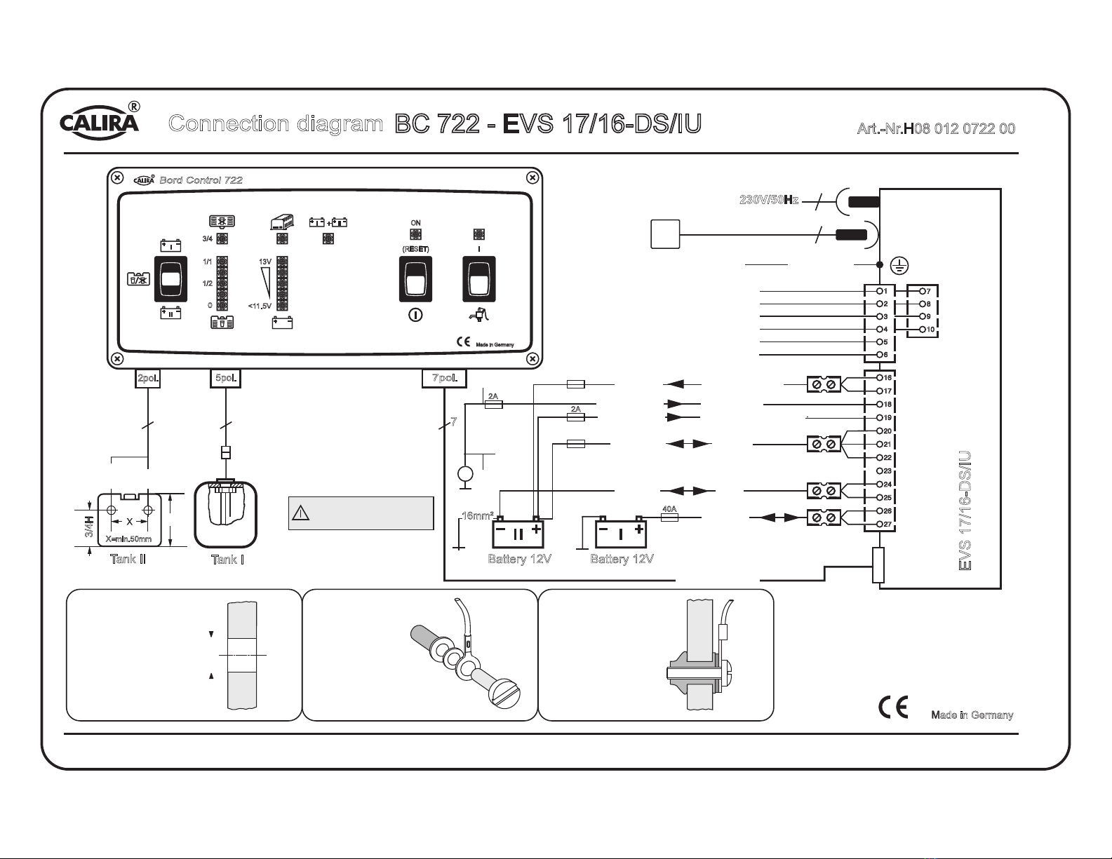
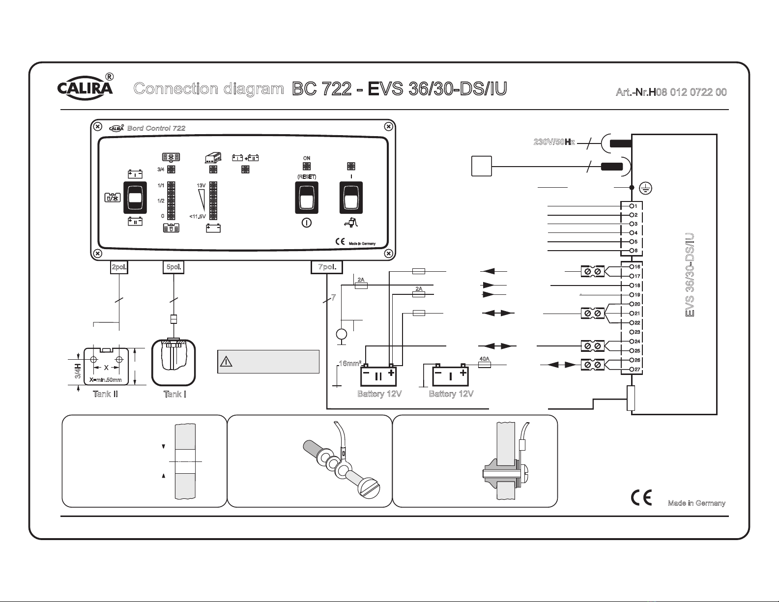
Funktionsbeschreibung
Bord Control 722
Taster zur Abfrage der Batteriespannungen und der Füllstände
des Frisch- und Abwassertanks.
LED zur Füllstandsanzeige des Abwassertanks. Leuchtet sobald
Abwassertank mehr als 3/4 gefüllt ist.
LED´s zur Füllstandsanzeige des Frischwassertanks in 1/4-
Stufen.
LED zur Anzeige des Ladevorganges.
LED´s zur Spannungsanzeige von Batterie I oder Batterie II.
LED zur Parallelschaltungsanzeige von Batterie I und II.
Hauptschalter für das Bord Control und Steuerschalter für das
Verbraucherrelais in der Elektroversorgung. Integrierte NOT-EIN-
Funktion zur kurzzeitigen Versorgung der Verbraucher, falls die
Unterspannungsabschaltung angesprochen hat.
Hauptschalter Kontroll-LED, leuchtet bei eingeschaltetem Hauptschalter,
geht aus, wenn die Unterspannungsabschaltung angesprochen hat.
Pumpenschalter zur Ansteuerung des Pumpenrelais in der
Elektroversorgung. Funktioniert nur bei eingeschaltetem Hauptschalter.
Pumpenschalter Kontroll-LED, leuchtet bei eingeschaltetem
Pumpenschalter.
1
2
3
4
5
6
7
8
9
10
I
II
III
Bord Control 722
1/1
0
1/2
3/4
13V
<11.5V
+
ON
(RESET)
I
Made in Germany

1
7 9
246
810
35
Pushbutton for checking the voltage of the batteries and the
content level of the fresh and waste water tank.
LED chain to show the tank content level of the fresh water
tank in quarters.
Charging control LED.
LED
LED to show the parallel connection of Battery I und II.
Level indicator LED waste water tank . Lights red if the waste
water tank is filled up to 3/4 or more.
chain to show the voltage of Battery I (start) or Battery II
(supply).
Main switch for the Bord Control and control switch for the consumer
relay in the power supply (EVS). Integrated emergency start function. The
consumers can be briefly activated if they were switched off by the
undervoltage protection circuit.
Main switch indicator LED, shines with switched on main switch and
goes out if the undervoltage protection circuit switched off.
Pumpe switch, controls the pump relay in the power supply (EVS). Works
only with switched on main switch.
Pump switch indicator LED, lights if the pump switch in switched on.
1
2
3
4
5
6
7
8
9
10
I
II
III
Bord Control 722
1/1
0
1/2
3/4
13V
<11.5V
+
ON
(RESET)
I
Made in Germany
Function description
Bord Control 722

B51 080994 00
40A
16
20
24
18
22
26
17
21
25
19
23
27
1
5
3
2
6
4
G
3
3
2
2pol. 5pol.
7pol.
5
Anschlußplan
40A
10mm² RT
6mm² RT
4mm² GN/GE
12V-Verbraucher 1 (20A)
12V-Verbraucher 2 (20A)
12V-Verbraucher 3 (20A)
Sofortlicht (20A)
Wasserpumpe (10A)
0,75mm² BR
0,75mm² RT
10mm² RT
6mm² BL
H
In die Tanks Löcher mit 9,5-
10,0mm bohren.
Bohrungen von außen, und möglichst
auch von innen, entgraten
9,5-10mm
Meßfühler zusammensetzen,
Schrauben dabei mit Dicht-
masse oder elastischem
Kleber einsetzen, Schrauben
zunächst nur lose von Hand
anziehen
-Meßfühler in die Tankbohrung
einsetzen
-Kabelfarben beachten- und mit
Schraubendreher fest anziehen.
Der Rand der Gummidichtung
wird dabei gegen die Außenwand
des Tanks gepreßt. Innen bildet
sich eine Gummiwulst, welche die
Bohrung zuverlässig abdichtet
BC 722 - EVS 36/30-DS/IU Art.-Nr.H08 012 0722 00
I
II
III
Bord Control 722
1/1
0
1/2
3/4
13V
<11.5V
+
ON
(RESET)
I
Made in Germany
EVS 36/30-DS/IU
Kühlschrank (20A)
230V/50Hz
230V Verteilung
230V Eingang
230V Ausgang
Potential-
ausgleich
Stecker
6-polig
Stecker
12-polig
Stiftgehäuse
7-polig
+ Ladestrom
D+Lichtmaschine
B+Meßleitung/Test
+Versorgen
minus
Kabelstrang EVS-BC
Batterie 12V
Batterie 12V
(starten)
(versorgen)
40A
16mm²
2A
Tank I
Tank II
(Frischwasser)
(Abwasser)
Kuppiungs-
stecker
orange
weiß
X=min.50mm
3/4H
2A
7
CALIRA Electronic GmbH & Co. KG Lerchenfeldstraße 9 87600 Kaufbeuren-Neugablonz

B51 080995 00
40A
16
20
24
18
22
26
17
21
25
19
23
27
1
5
3
2
6
4
G
3
3
2
2pol. 5pol.
7pol.
5
Connection diagram
25A
10mm² RD
0,75mm² RD
0,75mm² BR
6mm² RD
4mm² GN/YE
12V-Consumer 1 (20A)
230V Distribution
12V-Consumer 2 (20A)
12V-Consumer 3 (20A)
Continuous power (20A)
Water pump (10A)
Refrigerator (20A)
10mm² RD
6mm² BU
H
Drill holes into the tanks with 9,5-
10,0mm diameter.
Burr the holes from both sides.
9,5-10mm
Compose the sensor, insert the screw
with sealing compound and fasten
screws first only by hand.
Insert the sensor into the hole in the
tank and fasten it with a srew driver.
Note the wire colours. The edge of the
rubber gasket is pressed against the
outer surface of the tank. Inside the
tank it forms a rubber fold, which seals
up the hole sure.
BC 722 - EVS 36/30-DS/IU Art.-Nr.H08 012 0722 00
I
II
III
Bord Control 722
1/1
0
1/2
3/4
13V
<11.5V
+
ON
(RESET)
I
Made in Germany
Tank II Tank I
(Waste water) (Fresh water)
Connection
plug
Battery 12V Battery 12V
(supply) (start) Cable EVS - BC
Connector
7pole
Plug
12pole
Plug
6pole
230V Output
Potential
equalization
230V Input
+Supply
D Generator+
B+ Measuring cable/Test
minus
+Charging current
Fuses must be assembled near
to the +poles of the batteries
and D+ of the generator
orange
white
230V/50Hz
EVS 36/30-DS/IU
Made in Germany
40A
2A
2A
16mm²
7
3/4H
X=min.50mm
CALIRA Electronic GmbH & Co. KG Lerchenfeldstraße 9 87600 Kaufbeuren-Neugablonz
This manual suits for next models
1
Table of contents
Languages:
Other Calira Batteries Charger manuals