CAME G4040EZ Owner's manual

AUTOMATIC BARRIERS
FA00124-EN
English
EN
INSTALLATION AND OPERATION
G4040EZ

p.
2
- Manual code:
FA00124-EN
FA00124-EN v.
3
- 04/2017 - © Came S.p.A. - The manual's contents may be edited at any time without notice.
WARNING!
Important safety instructions.
READ CAREFULLY
PREMISE
• THIS PRODUCT MUST ONLY BE USED FOR THE PURPOSE FOR WHICH IT WAS DE-
SIGNED. ANY OTHER USE IS DANGEROUS. CAME S.P.A. IS NOT LIABLE FOR ANY
DAMAGE CAUSED BY IMPROPER, WRONGFUL AND UNREASONABLE USE. • PRODUCT
SAFETY AND CORRECT INSTALLATION ARE SUBJECT TO RESPECTING THE PRODUCT'S
TECHNICAL CHARACTERISTICS AND THE CORRECT INSTALLATION PROCEDURE, IN LINE
WITH PROFESSIONAL STANDARDS, SAFETY REGULATIONS AND USAGE SPECIFICATIONS,
AS SET OUT IN THE TECHNICAL DOCUMENTATION THAT COMES WITH THE PRODUCT. •
KEEP THESE PRECAUTIONS TOGETHER WITH THE INSTALLATION AND USAGE MANUALS
THAT COME WITH THE OPERATOR SYSTEM.
BEFORE INSTALLING
(CHECK THE CONTENTS: IF SOMETHING IS MISSING, DO NOT CONTINUE UNTIL YOU
HAVE COMPLIED WITH ALL SAFETY PROVISIONS)
• FITTING AND TESTING MUST ONLY BE PERFORMED BY QUALIFIED TECHNICIANS • LAY
THE CABLES, INSTALL AND CONNECT UP THE PRODUCT, AND RUN TESTING FOLLOWING
PROFESSIONAL PROCEDURES IN COMPLIANCE WITH THE STANDARDS AND REGULATIONS
IN FORCE • BEFORE BEGINNING ANY OPERATION, READ ALL INSTRUCTIONS CAREFULLY;
INCORRECT INSTALLATION MAY CAUSE SERIOUS HARM TO PEOPLE OR PROPERTY •
MAKE SURE THE BOOM IS IN GOOD MECHANICAL ORDER, BALANCED AND ALIGNED,
AND THAT IT OPENS AND CLOSES PROPERLY. IFREQUIRED, FIT SUITABLE PROTECTIVE
DEVICES OR USE SUITABLE ADDITIONAL SAFETY SENSORS • IFTHE OPERATOR IS TO BE
INSTALLED AT AHEIGHT OF OVER 2.5 MFROM THE GROUND OR OTHER ACCESS LEVEL,
MAKE SURE YOU HAVE ANY NECESSARY PROTECTIVE DEVICES OR WARNINGS IN PLACE •
MAKE SURE THAT THE OPENING AUTOMATIC BARRIER DOES NOT CREATE AHAZARD •
DONOT INSTALL THE OPERATOR UPSIDE DOWN OR ON ELEMENTS THAT COULD BEND.
IFNECESSARY, ADD SUITABLE REINFORCEMENTS TO THE ANCHORING POINTS • MAKE
SURE THE TEMPERATURE RANGE SHOWN ON THE OPERATOR IS SUITABLE FOR THE
INSTALLATION SITE • DONOT INSTALL ON SLOPING OR UNEVEN SURFACES • MAKE
SURE ANY SPRINKLER SYSTEMS CANNOT WET THE OPERATOR FROM THE GROUND UP.
INSTALLATION
• SUITABLY SECTION OFF AND DEMARCATE THE ENTIRE INSTALLATION SITE TO PRE-
VENT UNAUTHORISED PERSONS FROM ENTERING THE AREA, ESPECIALLY MINORS AND
CHILDREN • BECAREFUL WHEN HANDLING OPERATORS THAT WEIGH OVER 20 KG.
IFNEED BE, USE PROPER SAFETY HOISTING EQUIPMENT • THE CE-MARKED SAFETY
DEVICES (PHOTOCELLS, STEPPING PLATES, SAFETY EDGES, EMERGENCY BUTTONS,
ETC.) MUST BE FITTED IN COMPLIANCE WITH PROFESSIONAL STANDARDS AND THE
REGULATIONS IN FORCE, TAKING INTO ACCOUNT THE ENVIRONMENT, TYPE OF SER-
VICE REQUIRED AND THE WORKING FORCES APPLIED TO THE MOVING BARRIERS. ANY
POINTS AT WHICH THERE IS ARISK OF CRUSHING, SHEARING OR CONVEYING MUST
BE SENSOR-PROTECTED • ANY RESIDUAL RISKS MUST BE CLEARLY SHOWN • ALL
OPENING CONTROLS (BUTTONS, KEY-SWITCH SELECTORS, MAGNETIC READERS, ETC.)
MUST BE INSTALLED AT LEAST 1.85 MFROM THE PERIMETER OF THE BARRIER'S
WORKING AREA, OR WHERE THEY CANNOT BE REACHED FROM THE OUTSIDE THROUGH
THE BARRIER. ANY DIRECT CONTROLS (BUTTONS, TOUCH PANELS, ETC.) MUST BE
INSTALLED AT LEAST 1.5 MFROM THE GROUND AND MUST NOT BE ACCESSIBLE TO
UNAUTHORISED PERSONS • THE AUTOMATIC BARRIER MUST BEAR VISIBLE IDENTIFICA-
TION DATA . • BEFORE CONNECTING THE BARRIER TO THE POWER SUPPLY, MAKE SURE
THAT THE IDENTIFICATION DATA CORRESPOND TO THE MAINS DATA • THE AUTOMATIC
BARRIER MUST BE CONNECTED TO AN EFFECTIVE EARTHING SYSTEM THAT COMPLIES
WITH LEGAL STANDARDS.
• THE MANUFACTURER DECLINES ALL LIABILITY FOR USE OF NON-ORIGINAL PROD-
UCTS, WHICH WOULD ALSO RESULT IN WARRANTY LOSS • ALL HOLD-TO-RUN CON-
TROLS MUST BE FITTED IN PLACES FROM WHICH THE MOVING BARRIER AND TRANSIT/
MANOEUVRING AREAS ARE VISIBLE • WHERE MISSING, APPLY APERMANENT SIGN
SHOWING THE POSITION OF THE RELEASE DEVICE • BEFORE DELIVERING THE PRODUCT
TO THE USER, MAKE SURE THE SYSTEM IS COMPLIANT WITH STANDARDS EN 12453
AND EN 12445 (REGARDING IMPACT FORCES), AND ALSO MAKE SURE THE SYSTEM
HAS BEEN PROPERLY ADJUSTED AND THAT ANY SAFETY, PROTECTION AND MANUAL
RELEASE DEVICES ARE WORKING PROPERLY • APPLY WARNING SIGNS WHERE NECES-
SARY AND IN AVISIBLE PLACE (E.G. APANEL ON THE BARRIER).
USER INSTRUCTIONS AND RECOMMENDATIONS
• KEEP BARRIER OPERATION AREAS CLEAN AND FREE OF ANY OBSTRUCTIONS. MAKE
SURE THE OPERATING FIELD OF THE PHOTOCELLS AND MAGNETIC COILS IS CLEAR OF
ANY OBSTRUCTIONS • DONOT ALLOW CHILDREN TO PLAY WITH FIXED COMMANDS, OR
TO LOITER IN THE BARRIER MANOEUVRING AREA. KEEP ANY REMOTE CONTROL DEVICES
(TRANSMITTERS) OR ANY OTHER COMMAND DEVICE OUT OF THE REACH OF CHILDREN,
TO PREVENT THE OPERATOR FROM BEING ACCIDENTALLY ACTIVATED • THE APPARA-
TUS MAY BE USED BY CHILDREN OF EIGHT YEARS AND ABOVE AND BY PEOPLE WITH
PHYSICAL OR COGNITIVE DISABILITIES, OR THOSE LACKING EXPERIENCE OR RELEVANT
KNOWLEDGE, PROVIDED THEY ARE CLOSELY SUPERVISED OR ONCE THEY HAVE BEEN
PROPERLY INSTRUCTED ON HOW TO USE THE APPARATUS SAFELY AND ON THE POTEN-
TIAL HAZARDS INVOLVED. CHILDREN MUST NOT PLAY WITH THE APPARATUS. USER
CLEANING AND MAINTENANCE MUST NOT BE PERFORMED BY UNSUPERVISED CHILDREN
• FREQUENTLY CHECK THE SYSTEM FOR ANY MALFUNCTIONS OR SIGNS OF WEAR AND
TEAR OR DAMAGE TO THE MOVING STRUCTURES, OPERATOR COMPONENTS, ANCHOR-
ING POINTS AND DEVICES, CABLES AND ACCESSIBLE CONNECTIONS. KEEP ANY JOINTS
(HINGES) AND FRICTION POINTS (BOOM FLANGE) CLEAN AND LUBRICATED • PERFORM
FUNCTIONAL CHECKS ON THE PHOTOCELLS EVERY SIX MONTHS. ALWAYS MAKE SURE
THE PHOTOCELL GLASS COVERS ARE CLEAN (USE ADAMP CLOTH; DO NOT USE SOL-
VENTS OR CHEMICALS THAT COULD DAMAGE THE DEVICES) • IFREPAIRS OR MODIFICA-
TIONS ARE REQUIRED TO THE SYSTEM, RELEASE THE OPERATOR AND DO NOT USE IT
UNTIL THE SAFETY CONDITIONS HAVE BEEN RESTORED • CUT OFF THE ELECTRICAL
POWER SUPPLY BEFORE RELEASING THE OPERATOR FOR MANUAL OPENINGS. READ THE
INSTRUCTIONS • IFTHE POWER SUPPLY CABLE IS DAMAGED, IT MUST BE REPLACED BY
THE MANUFACTURER OR ITS AUTHORISED TECHNICAL ASSISTANCE SERVICE OR, IN ANY
CASE, BY SIMILARLY QUALIFIED PERSONS, TO PREVENT ANY RISK • USERS MUST NOT
PERFORM ANY OPERATIONS THAT ARE NOT EXPRESSLY REQUIRED OF THEM AND WHICH
ARE NOT LISTED IN THE MANUALS. FOR ANY REPAIRS, MODIFICATIONS, ADJUSTMENTS
AND NON-SCHEDULED MAINTENANCE, PLEASE CONTACT THE TECHNICAL ASSISTANCE
SERVICE • LOG THE WORK IN THE PERIODIC MAINTENANCE LOG.
FURTHER RECOMMENDATIONS FOR ALL
• KEEP AWAY FROM AND DO NOT LOITER NEAR THE BARRIER BOOM OR MOVING
MECHANICAL PARTS • DONOT ENTER THE AREA OF OPERATION WHEN THE BARRIER
IS MOVING • DONOT COUNTER OR OBSTRUCT THE OPERATOR'SMOVEMENT AS
THIS COULD CAUSE DANGER • ALWAYS PAY SPECIAL ATTENTION TO ANY DANGEROUS
POINTS, WHICH MUST BE LABELLED WITH SPECIFIC PICTOGRAMS AND/OR BLACK AND
YELLOW STRIPES • WHEN USING ASELECTOR SWITCH OR AHOLD-TO-RUN CONTROL,
KEEP CHECKING THAT THERE ARE NO PERSONS WITHIN THE OPERATING RANGE OF ANY
MOVING PARTS, UNTIL THE CONTROL IS RELEASED • THE BARRIER MAY MOVE AT
ANY TIME AND WITHOUT WARNING • ALWAYS CUT OFF THE POWER SUPPLY BEFORE
PERFORMING ANY MAINTENANCE OR CLEANING.
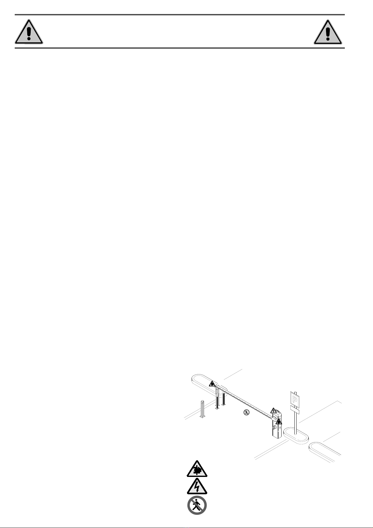
Danger of hand crushing
Danger! High voltage.
No transiting while the barrier is moving

MAX
p.
3
- Manual code:
FA00124-EN
FA00124-EN v.
3
- 04/2017 - © Came S.p.A. - The manual's contents may be edited at any time without notice.
KEY
This symbol shows the parts which must be read with care.
⚠This symbol shows the parts which describe safety issues.
☞This symbol indicates what should be communicated to users.
DESCRIPTION
Barrier with encoder made of varnished galvanised steel set up to fit accessories.
Intended use
The automatic barrier is designed to be used in public and private parking facilities.
Any installation and use other than that specified in this manual is forbidden.
Limits to use
Type G4040EZ
Maximum clearance width of the passage (m) 3.75
Technical data
Type G4040EZ
Protection rating (IP) 54
Power supply (V - 50/60 Hz) 230 AC
Motor power supply (V) 24 DC
Max draw (A) 15
Power (W) 300
Torque (Nm) 200
Opening time at 90° (s) 2 to 6
Duty cycle INTENSIVE SERVICE
Operating temperature (°C) -20 to +55
Reduction ratio (i) 1/202
Protection class I
Weight (Kg) 55
Dimensions (mm)

1
2
3
4
5
7
6
8
9
11
10
p.
4
- Manual code:
FA00124-EN
FA00124-EN v.
3
- 04/2017 - © Came S.p.A. - The manual's contents may be edited at any time without notice.
Description of parts
1. Dome cover
2. Motor shaft plate
3. Intermediate plate
4. Boom-attachment cover
5. Anti-shearing protective cover
6. Cabinet
7. Release lock
8. Inspection hatch lock
9. Rod
10. Inspection hatch
11. Control panel
12. Boom-adjustment mechanical stop
13. Lever arm
14. Gearmotor with encoder
15. EMC01 filter
16. Anchoring plate
17. Anchoring bracket
18. Clamp
Standard installation
1. Barrier with boom
2. Reflective strips
3. Luminous cord
4. Flashing light
5. Photocell casing
6. Photocell
7. Photocell post
8. Fixed rest
9. Coil
10. Control device post
11. Control device (keypad selector, transponder sensor)

p.
5
- Manual code:
FA00124-EN
FA00124-EN v.
3
- 04/2017 - © Came S.p.A. - The manual's contents may be edited at any time without notice.
GENERAL INSTALLATION INSTRUCTIONS
⚠Installation must be carried out by expert qualified personnel and in full compliance with the regulations in force.
Important! Using original CAME control and safety devices and accessories ensures easy installation and system maintenance.
Preliminary checks
⚠Before installation:
• make sure the plate is anchored to a solid spot;
• make sure that the power supply network is equipped with a suitable all-pole disconnection device, which provides full cut-off in category III
power surge conditions, as required by the installation regulations (i.e. contacts are more than 3 mm apart);
• make sure that any connections inside the case (for protective circuit continuity) are fitted with extra insulation as compared to the other
conductive parts inside;
• set up suitable tubes and conduits for the electric cables to pass through, making sure they are protected from any mechanical damage.
Tools and materials
Make sure you have all the tools and materials you need to install the product in complete safety and in compliance with the current regulations.
The following figure shows some basic equipment needed by the installer.
Types of cable and minimum sizes
Connection Type of cable Cable length
1 < 15 m
Cable length
15 < 30 m
Control panel power supply 230 V AC H05RN-F 3G x 1.5 mm23G x 2.5 mm2
Photocell transmitters FROR CEI 20-22
CEI EN
50267-2-1
2 x 0.5 mm2
Receiver photocells 4 x 0.5 mm2
Control and safety devices 2 x 0.5 mm2
Antenna RG58 max 10 m
Metal mass detector (see product literature)
If cable lengths dier from those specified in the table, establish the cable sections depending on the actual power draw of the connected
devices and according to the provisions of regulation CEI EN 60204-1.
For multiple, sequential loads along the same line, the dimensions in the table need to be recalculated according to the actual power draw and
distances. When connecting products that are not specified in this manual, please refer to the documentation provided with those products.

500
340
400
r 40
p.
6
- Manual code:
FA00124-EN
FA00124-EN v.
3
- 04/2017 - © Came S.p.A. - The manual's contents may be edited at any time without notice.
INSTALLATION
⚠The following illustrations are examples. The space for fastening the barrier and accessories varies depending on where it is installed. The
installer must find the most suitable solution.
⚠Caution! Use hoisting equipment to transport and position the barrier.
During set-up and installation, the barrier could be unstable and tip over. Be careful and do not lean on it until it is fully fastened.
Preparing the fastening plate
⚠If the flooring does not provide a sturdy surface to fasten the cabinet to, use a cement slab.
Dig a hole for the foundation frame.
Prepare the corrugated tubes you will need for the cables coming out of the junction pit.
The number of tubes depends on the type of system and the accessories you are going to fit.
Prepare a foundation frame that is larger than the anchoring plate and sink it into the dug hole.
Insert an iron cage into the foundation frame to reinforce the concrete.
Attach the four anchoring clamps to the anchoring plate.
Place the plate over the iron cage.
Fill the foundation frame with concrete. The base must be perfectly level and the bolts entirely above surface.
Wait at least 24 hrs for the concrete to solidify.
Remove the foundation frame.

1
NM
4
2
3
p.
7
- Manual code:
FA00124-EN
FA00124-EN v.
3
- 04/2017 - © Came S.p.A. - The manual's contents may be edited at any time without notice.
⚠Caution! The barrier is set up for installing on the left.
If it is installed on the right, invert the boom opening direction, following the procedure below:
- remove the rod from the transmission arm ;
- release the gearmotor using the key;
- turn the transmission arm ;
- lock the motor again;
- fasten the rod to the opposite hole in the arm ;
- invert the motor phases M and N.
Left
Right
Fill the hole with earth around the concrete block.
Remove the nuts and washers from the bolts.
Insert the electric cables into the tubes so that they protrude by about 600 mm.
Preparing the barrier
Remove the screws from the dome cover, insert the key in the lock and turn it anti-clockwise.
Lift up the dome cover and remove the inspection hatch .

G03756
G03750
UNI5931 M8X20
p.
8
- Manual code:
FA00124-EN
FA00124-EN v.
3
- 04/2017 - © Came S.p.A. - The manual's contents may be edited at any time without notice.
Attach the intermediate plate and boom-attachment cover to the attachment plate with a screw. Leave the screw loose to make it easier to insert
the boom.
Attachment plate
Intermediate plate
Boom-attachment
cover
Installing the barrier
The cabinet should be installed with the inspection hatch on the most accessible side to make any adjusting easier.
Place the cabinet onto the anchoring plate and fasten it using nuts and washers.
⚠For assemblies with the G03750 boom, you must insert the
G03756 reinforcement.

UNI5931 M8x12
UNI5931 M8x20
L
1
3
4
2
UNI6954 ø2,9x13
UNI6954 ø3,9x19
p.
9
- Manual code:
FA00124-EN
FA00124-EN v.
3
- 04/2017 - © Came S.p.A. - The manual's contents may be edited at any time without notice.
Fit the boom into the attachment cover and fasten it using the screws.
Cut the groove covers to the required length and insert them in the boom conduits on both sides .
Insert the shockproof rubber profile in the boom and cut off the excess .
Fit the boom cap using the screws .
Place the anti-shearing protective cover over the boom-attachment cover and fasten it in place using the screws. .

1
2
3
p.
10
10 - Manual code:
FA00124-EN
FA00124-EN v.
3
- 04/2017 - © Came S.p.A. - The manual's contents may be edited at any time without notice.
Release the gearmotor and position the boom vertically . Lock the gearmotor again.
Screw the eyelet rod on the end of the spring . Screw the spring on the rod fixed to the lever arm .
PASSAGE CLEARANCE (max. 3.75 m)
A
001G02040 Ø 40 mm spring
B
001G04060 Ø 50 mm spring
C001G06080 Ø 55 mm spring
BOOM COMPOSITION
1.5 to 1.75 1.75 to 2.25 2.25 to 2.75 2.75 to 3.25 3.25 to 3.5 3.5 to 3.75
Boom with shockproof profile
AAABBC
Boom with shockproof profile and 001G028401
luminous cord
AABBBC
Boom with 001G0465 skirt
A B B C C
Boom with 001G028401 luminous cord and
001G0465 skirt
A B B C C
Boom with shockproof profile and 001G02808 swing
rest
A B B C
Boom with shockproof profile, 001G028401 luminous
cord and 001G02808 swing rest
A B B C
⚠WARNING!
001G02802 cannot be used on barriers with booms fitted with the 001G0465 skirt or 001G02808 swing post
001G02808 for clearance widths of up to 3 m.
001G02807 MUST be used with clearance widths exceeding 3 m.
001G0465 - 001G02808 cannot be used together.
The boom includes the transparent groove cover and end cap.
Balancing the boom
Before proceeding, check that the spring you have chosen is suitable for the accessories and the clearance.

45°
45°
4
5
6
p.
11
11 - Manual code:
FA00124-EN
FA00124-EN v.
3
- 04/2017 - © Came S.p.A. - The manual's contents may be edited at any time without notice.
Fix the counter nut and lock the gearmotor again .
Check the spring is working properly.
With the boom positioned vertically, the spring is not taut.
With the boom positioned horizontally, the spring is taut.
Hook the eyelet rod onto the anchoring bracket .
Release the gearmotor and manually turn the spring to increase or reduce the traction . The boom should stabilise at 45°.

17 19
18
4
5
14 13 9 7
16
2
10
11
12 6
21
3
822
3
26V
0V
230
0
20
23
1
15
p.
12
12 - Manual code:
FA00124-EN
FA00124-EN v.
3
- 04/2017 - © Came S.p.A. - The manual's contents may be edited at any time without notice.
ELECTRICAL CONNECTIONS
⚠Warning! Before working on the control panel, cut off the main current supply and remove any batteries.
Power supply to control panel and control devices: 24 V AC/DC.
The input and output contact functions, the timing settings and user management are set and shown on the display.
All connections are quick-fuse protected.
Important! Inside the control panel, apply ferrite (FAIR-RITE 31 SPLIT ROUND CABLE ASSEMBLY art. 0431177081, not supplied)
to the control, signalling and safety device cables.
Description of parts
1. Transformer
2. Terminal board for power supply
3. Terminal board for transformer
4. Terminal board for gearmotor
5. Terminal board for encoder
6. Control-board fuse
7. Voltage signalling LED
8. Programming warning LED
9. Memory roll card connector
10. Programming buttons
11. R700 / R800 card connector
12. RSE card connector
13. AF card connector
14. Terminal board for antenna
15. Terminal board for control and safety devices
16. Terminal board for paired / alternate / CRP connection
17. Terminal board for keypad selector
18. Terminal board for transponder devices
19. Display
20. Accessories fuse
21. Line fuse
22. Terminal board for thermal cut-off switch
23. Ferrite
FUSE TABLE ZL39
- Line 3.15 A-F = 120 V
1.6 A-F = 230 V
- Control board 1 A-F
- Accessories 2 A-F

L1T L2T M N + E -
A B GND A B S1 GND
L1T L2T
24V 0 THERMAL
L N
10 11
L N
+
-
26V
0V
230
0
p.
13
13 - Manual code:
FA00124-EN
FA00124-EN v.
3
- 04/2017 - © Came S.p.A. - The manual's contents may be edited at any time without notice.
Power supply
Power supply to accessories output:
- a 24 V AC normally;
- a 24 V DC when the emergency batteries are operating;
Max. power: 40 W
Red
White
Blue
Orange
Ferrite Transformer
230 V AC - 50/60 Hz
24 V DC gearmotor with
encoder
The gearmotor is already connected.
For installations to the right of the barrier, follow the instructions in the section PREPARING THE BARRIER.
Factory wiring
Ferrite
White
Brown
Green
Brown
Blue
EMC01 filter

10 11 E1 E6 Rx Tx 1 2 3 3P 4 5 7 CX CY
A B GND A B S1 GND
CAME
ACCESSCONTROL
AF
R700
R800
p.
14
14 - Manual code:
FA00124-EN
FA00124-EN v.
3
- 04/2017 - © Came S.p.A. - The manual's contents may be edited at any time without notice.
CLOSE function from control device (N.O. contact).
Warning: in HOLD-TO-RUN mode, the control device must
be connected to 2-4.
Command and control devices
Antenna with RG58 cable
STOP button (N.C. contact). For stopping the boom while
excluding automatic closing. To resume movement either
press the control button or any other control device.
If unused, select 0 (Disabled) from the function F 1.
OPEN-CLOSE-INVERT (step-by-step) function from
control device (N.O. contact).
Keypad selector
Transponder or card reader
Insert the decoding card (R700) for the
TSP00 sensor or LT001 card reader to be
recognised.
Insert the decoding card (R800)
so that the keypad selector is
recognised.
WARNING! Before inserting any plug-in card (e.g. AF, R800), LINE VOLTAGE MUST BE DISCONNECTED. If installed, disconnect the batteries.
Insert the AF card to control the
barrier via a transmitter.
Warning! OPEN function from control device (N.O.
contact), to be connected only for paired or alternate
systems. (See PAIRED or ALTERNATE CONNECTION)
OPEN function from control device (N.O. contact).
Warning: in HOLD-TO-RUN mode, the control device
must be connected to 2-3.
Red
Black
White
Blue

10 11 E1 E6 Rx Tx 1 2 3 3P 4 5 7 CX CY
RX TX
./ # .#
10 11 E1 E6 Rx Tx 1 2 3 3P 4 5 7 CX CY
RX TX
10 11 E1 E6 Rx Tx 1 2 3 3P 4 5 7 CX CY
p.
15
15 - Manual code:
FA00124-EN
FA00124-EN v.
3
- 04/2017 - © Came S.p.A. - The manual's contents may be edited at any time without notice.
DIR
photocells
DELTA-S
photocells
DELTA
photocells
Safety devices
Configure (N.C.) contacts CX or CY, input for
safety devices such as photocells, that comply with standard EN
12978.
Input CX (function F 2) or CY (function F 3).
C1 reopening while closing. When the boom is closing, opening
the contact causes the motion to invert until fully opened;
C4 obstacle stand-by. It stops the boom, if moving, and restarts
movement once the obstacle has been removed.
C5 immediate closing. Closing the boom after a vehicle has
passed through the operating area of the safety devices.
C9 immediate closure with obstacle stand-by during closing.
Closing the boom after a vehicle has passed through the
operating area of the safety devices.
During closing, the devices also run function C4, obstacle
stand-by.
If the CX and CY contacts are not used, they must be
disabled during programming.
Open-barrier signal output (contact rating: 24 V AC - 3 W max).
It shows the barrier status (function F 10).
Luminous cord (contact rating: 24 V AC - 32 W max).
It flashes when the boom opens and closes (function F 15).
Signalling devices
Additional light connection output (contact rating: 24 V AC - 25 W max):
- dome flashing light: it flashes when the barrier opens and closes.
- beacon or courtesy light: outdoor light, which can be positioned freely, for better
illumination in the parking/driveway area.
Beacon: it stays on from the moment the boom begins to open until it is fully closed
(including automatic closing time).
Courtesy light: it stays on for a set time of between 60 and 180 seconds (function F 18).

N.O.
N.C.
C.
+ - + -
DELTA
10 11 E1 E6 Rx Tx 1 2 3 3P 4 5 7 CX CY
FUSIBILE 200mA
TX 2
TX 2
10 2 TX C
-
+ -
NC
+ -
DIR / DELTA S
10 11 E1 E6 Rx Tx 1 2 3 3P 4 5 7 CX CY
N.O.
N.C.
C.
+ - + -
DELTA
10 11 E1 E6 Rx Tx 1 2 3 3P 4 5 7 CX CY
FUSIBILE 200mA
TX 2
TX 2
10 2 TX C
-
+ -
NC
+ -
DIR / DELTA S
10 11 E1 E6 Rx Tx 1 2 3 3P 4 5 7 CX CY
A B GND
A B GND
UTP CAT 5
1 2 3 4
1
2
3
4
RSE
p.
16
16 - Manual code:
FA00124-EN
FA00124-EN v.
3
- 04/2017 - © Came S.p.A. - The manual's contents may be edited at any time without notice.
Connecting the safety devices (safety test)
At each opening and closing command, the control board assesses the efficiency
of the safety devices (e.g. photocells).
Any anomaly found inhibits any command and the message Er4 shows on the
display.
Activate function F 5 from programming.
Connecting the safety devices (sleep mode)
The "Sleep mode" function reduces the energy consumption in stand-by.
Select 1 from the function F 60.
Insert the RSE card.
Connection for paired or alternate operation and for Came Remote Protocol (CRP only for ZL39EX)

~1°
~89°
+-
+
-
~1°
~89°
+
-
+
-
p.
17
17 - Manual code:
FA00124-EN
FA00124-EN v.
3
- 04/2017 - © Came S.p.A. - The manual's contents may be edited at any time without notice.
Establishing the limit-switch points
Close the inspection hatch and power the system. Activate the boom to check whether it is parallel to the road surface when closed and at about
89° when open.
⚠The inspection hatch must be closed when the boom opens and closes.
To correct the vertical position of the boom:
- lower the boom;
- open the inspection hatch;
- turn the mechanical opening stop clockwise to increase the boom travel or anticlockwise to decrease it .
Fasten the stop using a counter nut .
To correct the horizontal position:
- lift the boom;
- turn the mechanical closing stop clockwise to increase the boom travel or anticlockwise to decrease it .
Fasten the stop using a counter nut .

Fi
Fi
F2
F3
0
i
03
i3
S1 GND
{
{
{
p.
18
18 - Manual code:
FA00124-EN
FA00124-EN v.
3
- 04/2017 - © Came S.p.A. - The manual's contents may be edited at any time without notice.
To enter the menu, press and hold
the ENTER key for at least one
second.
To select a menu item,
use the arrow keys...
... then press ENTER
also use the arrow keys
for the submenus...
To increase or decrease
a value, use the arrow
keys...
...to exit the menu, wait 10 seconds or press
ESC.
...then press ENTER to
confirm...
Menu navigation
... then press ENTER
Display
Description of setting commands
⚠During programming, the barrier must be stopped.
PROGRAMMING
The ESC key is for:
- exiting the menu;
- cancelling modifications.
The < > keys are for:
- shifting from one menu item to another;
- increasing or decreasing values.
The ENTER key is for:
- entering the menu;
- confirming and saving the values set.

p.
19
19 - Manual code:
FA00124-EN
FA00124-EN v.
3
- 04/2017 - © Came S.p.A. - The manual's contents may be edited at any time without notice.
Functions mapping
F 1 Total stop function (1-2)
F 2 Function associated with CX input
F 3 Function associated with CY input
F 5 Safety test function
F 6 Hold-to-run function
F 9 Obstruction detection function with motor idle
F 10 Function associated with the open-barrier signal output
F 11 Exclude encoder
F 14 Sensor type selection function
F 15 Luminous cord intermittence function
F 18 Additional light function
F 19 Automatic closing time
F 21 Pre-flashing time
F 22 Working time
F 25 Courtesy light time
F 28 Opening speed adjustment
F 29 Closing speed adjustment
F 30 Opening slow-down speed adjustment
F 31 Closing slow-down speed adjustment
F 33 Calibration speed adjustment
F 34 Sensitivity during travel
F 35 Sensitivity during slow-down
F 37 Adjustment of opening slow-down starting point
F 38 Adjustment of closing slow-down starting point
F 49 Managing serial connection
F 50 Save data to the memory roll
F 51 Read data on the memory roll
F 52 Parameter transfer from Master to Slave
F 56 Peripheral number
F 60 Sleep mode
F 61 Pre-flashing function
F 63 Change COM speed
U 1 Entering a user with an associated command
U 2 Delete a single user
U 3 Delete all users
A 1 Set boom type
A 2 Motor test
A 3 Travel calibration
A 4 Parameter reset
A 5 Manoeuvre count
H 1 Software version
Functions menu
IMPORTANT! Start programming these functions first: SET BOOM TYPE (A1), MOTOR TEST (A2), TOTAL STOP (F1) and TRAVEL
CALIBRATION (A3).
F1 Total stop [1-2] 0 = Deactivated (default) / 1 = Activated
N.C. Input – Stop barrier while excluding automatic closing; to resume movement, use the command device. The safety device should be
inserted in [1-2].
F2 Input [2-CX] 0 = Deactivated (default) / 1 = C1 / 4 = C4 / 5 = C5 / 9 = C9
N.C. Input – Possible associations: C1 = reopening during closing by photocells, C4 = obstacle stand-by, C5 = immediate closure,
C9 = immediate closure with obstacle stand-by during closing.
F3 Input [2-CY] 0 = Deactivated (default) / 1 = C1 / 4 = C4 / 5 = C5 / 9 = C9
N.C. Input – Possible associations: C1 = reopening during closing by photocells, C4 = obstacle stand-by, C5 = immediate closure,
C9 = immediate closure with obstacle stand-by during closing.
F5 Safety test 0 = Deactivated (default) / 1 = CX / 2 = CY / 3 = CX+CY
After each opening and closing command, the board checks that the photocells are working correctly.

p.
20
20 - Manual code:
FA00124-EN
FA00124-EN v.
3
- 04/2017 - © Came S.p.A. - The manual's contents may be edited at any time without notice.
F6 Hold-to-run 0 = Deactivated (default) / 1 = Activated
Press and hold a button to open and close the barrier. Opening button on contact 2-3; closing button on contact 2-4. All other command
devices, including radio-controlled devices, are excluded.
F9 Obstruction detection
with motor idle
0 = Deactivated (default) / 1 = Activated
With the barrier open or closed or after a total stop, if the safety devices (photocells or safety edges) detect an obstacle the operator remains
stationary.
F10 Open-barrier signal
output
0 = on with boom raised and moving (default) /
1 = flashes intermittently every half second during opening
flashes intermittently every second during closing
on with boom raised
o with boom lowered
It signals the barrier status. The signalling device is connected to contact 10-5.
F11 Encoder 0 = Activated (default) / 1 = Deactivated*
It manages slow-downs, obstruction detection and sensitivity.
* Connect the micro-switches to F-FC-FA.
F14 Sensor type selection 0 = control with transponder sensor or magnetic card reader /
1 = control with keypad selector (default).
Setting the type of sensor to control the barrier.
F15 Luminous cord signal
output
0 = Boom moving (default) / 1 = Boom moving and closed
It signals the status of the barrier with intermittent lights. Luminous cord connected to contact 10-E6.
F18 Additional light 0 = Flashing light (default) / 1 = Beacon / 2 = Courtesy light
Output on 10-E1.
The flashing light functions during opening and closing.
The beacon stays on from the moment the barrier begins to open until it is fully closed (including automatic closing time). Where the automatic
closing function is not activated, it only stays on during barrier movement.
The courtesy light either stays on for a fixed period of 180 seconds or can be adjusted; see function F 25.
F19 Automatic closing time 0 = Deactivated (default) / 1 = 1 second / ... / 180 = 180 seconds
The waiting time before the barrier closes automatically starts when the limit-switch point is reached during opening. The time can be set to
between 1 second and 180 seconds. The barrier is not closed automatically where the safety devices are triggered by an obstacle, after a total
stop or where there is no power.
F21 Pre-flashing time 0 = Deactivated (default) / 1 = 1 second / … / 5 = 5 seconds
Adjusting the pre-flashing time of the flashing light connected to 10-E1 before each manoeuvre. The flashing time can be set to between 1
second and 10 seconds.
F22 Working time 5 = 5 seconds / … / 120 = 120 seconds (default)
Gearmotor cycle time during opening or closing.
The working time can be set to between 5 seconds and 120 seconds.
F25 Courtesy light time 60 = 60 seconds / … / 180 = 180 seconds (default)
Additional light; it stays on when the barrier opens and closes.
The time can be set to between 5 seconds and 120 seconds.
F28 Opening manoeuvre
speed
70 = Minimum speed / … / 100 = Maximum speed.
Setting the boom opening speed, calculated as a percentage.
⚠Warning: the speed parameter fields vary according to the type of boom:
- for booms with a joint, between 2 m and 4 m, set the speed percentage from 70 to 100;
- for booms between 6 m and 8 m, set the speed percentage from 80 to 100.
F29 Closing manoeuvre
speed
70 = Minimum speed / … / 100 = Maximum speed.
Setting the boom closing speed, calculated as a percentage.
⚠Warning: the speed parameter fields vary according to the type of boom:
- for booms with a joint, between 2 m and 4 m, set the speed percentage from 70 to 100;
- for booms between 6 m and 8 m, set the speed percentage from 80 to 100.
F30 Opening slow-down
speed
15 = Minimum speed / … / 40 = Maximum speed
Setting the boom opening slow-down speed, calculated as a percentage.
⚠Warning: the speed parameter fields vary according to the type of boom:
- for 2 m booms with a joint, set the slow-down speed percentage from 20 to 40;
- for 4 m booms, set the slow-down speed percentage from 20 to 30.
- for booms between 6 m and 8 m, set the slow-down speed percentage from 15 to 40.
Table of contents
Other CAME Automatic Barrier manuals

CAME
CAME GARD series User manual

CAME
CAME CAT Series User manual

CAME
CAME G03003 User manual

CAME
CAME G4001 User manual

CAME
CAME 803XA-0070 User manual

CAME
CAME GARD8 Series User manual

CAME
CAME GARD series User manual

CAME
CAME G40001-316 User manual

CAME
CAME 803XA-0200 User manual

CAME
CAME GARD series User manual

CAME
CAME G4041 User manual

CAME
CAME 803XA-0230 User manual

CAME
CAME GARD PT Series User manual

CAME
CAME Ozak GARD Series User manual

CAME
CAME G2080EZC User manual

CAME
CAME GARD PX Brushless User manual

CAME
CAME GARD PX Series User manual

CAME
CAME G6000T User manual

CAME
CAME G2080Z User manual

CAME
CAME GARD 4 SERIES User manual