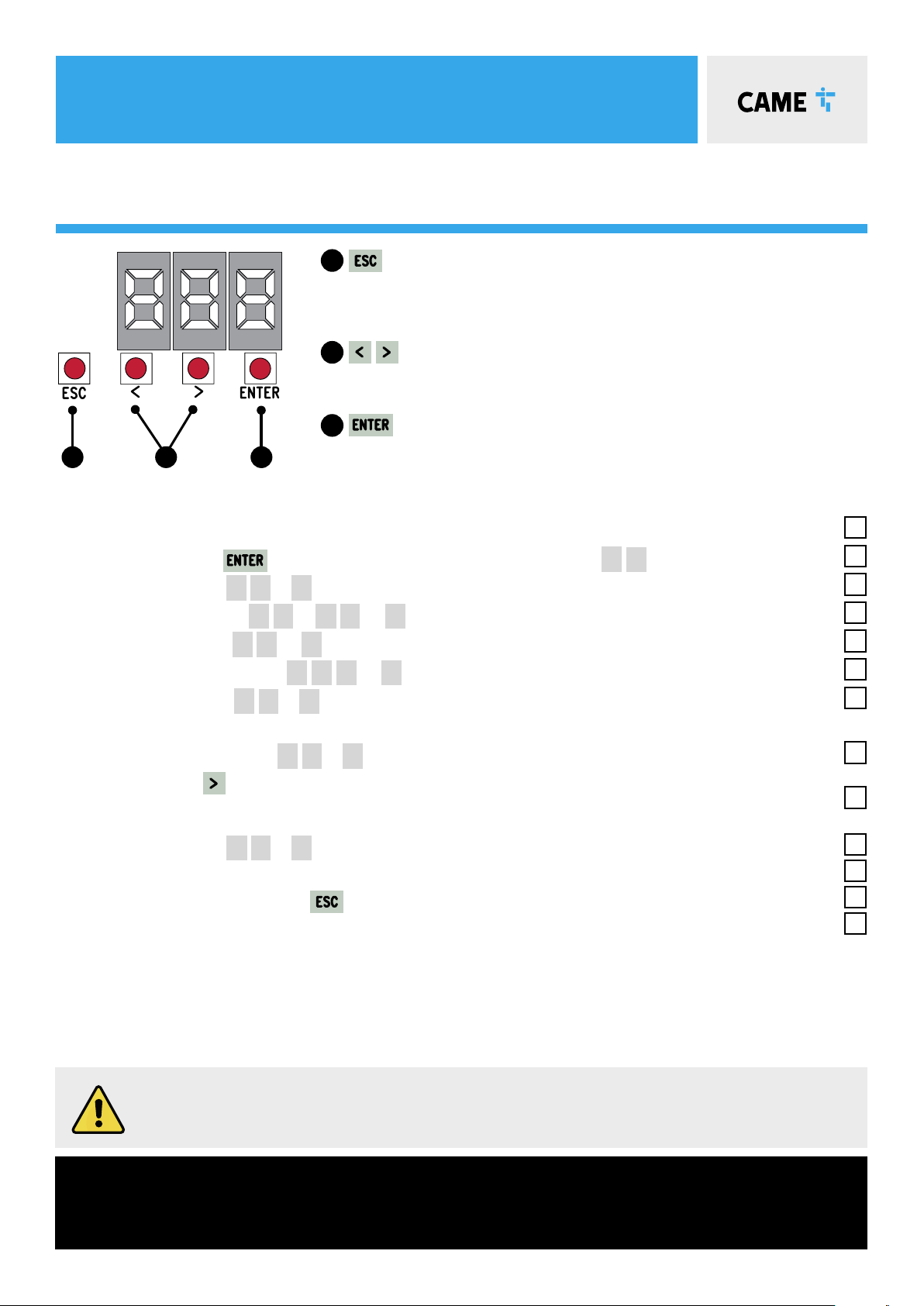
CAME 8K01MB-0572 STYLO KIT User manual

CAME.COM/UK
8K01MB-0572 stylo kit
Complete kit for a single swing gate weighing
up to 100kg per leaf / max. width 1.8m
QUICK SETUP GUIDE
Typical gate setup & geometry
Gate motor manual release
Kit wiring diagram
Control panel guide & safety
TO BE READ IN CONJUNCTION WITH THE FULL INSTRUCTION MANUAL

CONTENTS
DIR10
Pair of Photocells
ZL92Z
Control Panel
top-a433n
Tuned Antenna
STYLO-BS
Articulated Drive Arm
TOP44RBN
Rolling code Transmitter
STYLO-ME
Motor
x2
8K01MB-0572: KIT CONTENTS
AF43S
Radio Frequency Card
1Kit Contents
2Safety Instructions
3Typical Gate Setup
4Geometry
5Manual Release Instructions
6Kit Wiring Diagram
7Control Panel:
Quick Start Guide
8Control Panel:
Programming Transmitters
9Control Panel: Safety
10 Optional Accessories

SAFETY INSTRUCTIONS
When correctly installed in compliance to installation instructions and adhering to all
current electrical, mechanical and manufacturer regulations, your automation system
will provide a high degree of safety and problem free operation.
Please take note of the following warnings that must be followed in order to
prevent accidents during your gate operation:
• Do not allow children to play near the gate.
• Keep all remote control operating devices out of the reach of children.
• Do not pass through the gate whilst in operation. Wait until they are fully open before passing through.
• Do not stop unnecessarily when passing through the gate.
• Keep feet away from the bottom of the gate during operation.
• Do not operate the gate by remote control unless it is in view.
• Do not attempt to block or interfere with the gate movement during operation.
• Under no circumstances should you attempt to modify the gate automation system.
• Ensure that your gate is serviced at 3 to 12 month intervals (dependent on number of openings) by your installation/
maintenance company.
• Report any signs of malfunction to your installation/maintenance company immediately.
• In the case of malfunction, isolate the power supply, release any additional locking mechanism, manually open the
gate (see manual release instruction booklet) and call your installation/maintenance company.
• If you are in any doubt regarding the operation of your gate, call your installation/maintenance company.

STYLO: TYPICAL GATE SETUP
CONTROL PANEL
PHOTOCELLS
• The control panel should be mounted in an accessible position and not directly behind the gates, to avoid a
potential crushing hazard.
• Use cable glands to connect the devices to the control panel. One of these must be used exclusively for the
power supply cable.
• All holes should be sealed to avoid ingression and maintain the IP54 protection rating.
Only a competent service provider should open the enclosure
and adjust the settings.
• The photocells are used in pairs, one transmitter and one receiver.
• They should be installed between 500-600mm from the ground, facing each other.
• Power for the photocells is taken from the control panel 24v AC.
• The maximum range of the photocell should always be observed.
When the photocell beam is broken, the control panel can be programmed on how to react.
Please see ‘Safety’ section for more information.
1
7
8
9
25
34
6
OUTSIDE OF GATES
INSIDE OF GATES
1STYLO Motor 4Flashing Light (optional) 72nd set of Photocells (optional)
2Control Panel 5Selector Keypad (optional) 8Mechanical End Stop (not supplied)
3Reception Antenna 6Photocells (on outside of gate posts) 9Photocell column (optional accessory)

stylo-BS: GEOMETRY
Ø 3,5 x 9,5
Preliminary checks
Side hung gate GEOMETRY: STYLO-ME / STYLO-BS
Tick
1. Check that the gate structure is sturdy enough, the hinges work eciently and that there is
no friction between the fixed and moving parts
2. Make sure that measurement Cdoes not exceed the value shown in the reference table
3. Make sure that you have fitted opening and closing mechanical gate stops
• The greater the motor angle, the greater the opening speed
and the slower the gear motor’s thrust.
• The smaller the motor angle, the slower the opening speed
and the greater the gear motor’s thrust.
i
i= 300 mm max
with 90° opening
DA
C
OUTward OPENING gates
For outward opening gate geometry
please refer to the full Installation Manual.
Remove the lower cap
from the gearmotor
Secure the gearmotor to
the flange using the four
bolts supplied
Secure the upper cap
Securing the transmission arm
1. Assemble the hinged arm by joining the two half-arms
with nuts and bolts. Lubricate the rotation pins (1).
2. Insert the hinged arm onto the gearmotor shaft and
secure it using the screw and washer (2).
3. Release the gearmotor, open the gate leaf and hook
the arm using the nuts and bolts (3).
4. Cover the hole using the cap (4).
UNI 6593 Ø 6x18
UNI 5739 Ø 6x10
Ø 10x39 UNI 5739 Ø 10x14
UNI 6592
Ø 12x24
UNI 6593
Ø 6x18
UNI 5739
M6x10
O-Ring 4100
Opening A (mm) C (mm) D (mm)
90°90 0 ÷ 180 450
90°130 180 450
120°170 0 450

STYLO: MANUAL RELEASE
To manually RELEASE THE NON-REVERSIBLE GEARMOTOR:
1. Slide open the hatch covering the lock A
2. Insert key into lock and turn until it clicks B
3. With your other hand firmly open the gate. The gate should be manually released. Now fully open the gate carefully at
the same speed as the automatic operator.
4. To re-engage, close the gate and turn the key back to its original position. Attempt to manually move the gate to
ensure it is fully engaged.
5. To re-engage, close the gate and return the release lever back to its original position, pushed completely back into
place. Take the key out and replace the cap B. Attempt to manually move the gate to ensure it is fully engaged.
Basic Maintenance: Hints & Tips
• Slide back manual release cover & spray locking
mechanism with suitable penetrating lubricant.
• Lubricate gate hinges.
• Manually release the gates at least once per month.
The STYLO articulated arm swing gate operator has a release mechanism located behind
the hatch at the bottom of the unit.
ALWAYS isolate the power supply as
instructed by your installer (even in a
power cut).
Release any additional locking
device fitted to the gate (eg. electric
lock etc).
a B

STYLOA-S24: wiring diagram
26V
0V
17V
0
230V
L N
S1 GNDA BB1 B2
10 11 EM2 N2 E2E1 ENC2 EB2M1 N1 ENC1 EB1 TS 1 2 3 3P CX CY4 5 7
ZL92Z
Control Panel
STYLO-ME
Gate motor
Cable/length
1m - 20m = 4 Core 1.5mm
20m - 30m = 4 Core 2.5mm
+ -
10 2 TX C NC TX 2
RX TX
DIR
Photocells
Cable/length
RX 4 Core 0.5mm Flex
TX 4 Core 0.5mm Flex
1m - 30m
AF43S
Plug-in
TOP-A433N
Antenna
Cable/length
RG58
Max. 5m
Mains Supply
230 V AC
Cable/length
1m - 20m = 3 Core 1.5mm
20m - 30m = 3 Core 2.5mm

ZL92Z: QUICK START GUIDE
Should the gates not operate as suggested above,
call CAME helpline 0115 921 0430 for technical support.
Important!
Ensure the wiring is complete (refer to the wiring diagram) & any required physical stops are set before
commencing with programming Tick
1. Power on the control panel
2. Press and hold the button for 2 seconds to access programming. ( F1 appears on the display).
3. Disable total stop – F1 – O
4. Disable safety inputs – F2& F3– O
5. Disable safety test – F5– O
6. Set the number of motors – F46– 1
7. Set the motor type – A1 – 1
CAUTION, Ensure the gate movement area is clear of all obstructions
8. Check the motor direction A2– 1
Press and hold
The gate should open, if not reverse the motor cables for motor 2 (Connections M2, N2)
Leave the gate in the halfway position.
9. Setup the Encoder A3– 1
10. The Gate will now perform a close and open cycle.
12. Exit the programming using the button.
13. Check the gate operation by pulsing across connections 2 & 7, the gate will close
Please refer to the main manual for:
Changing automatic closing time, adjusting encoder settings if required
Safety inputs should now be configured and the gate force tested as required.
Please refer to the full manual to complete the commissioning.
The installation must be carried out
by skilled and qualified personnel
button - used to perform the following operations:
• Exit the menu
• Delete the changes
• Go back to the previous screen
buttons - used to perform the following operations:
• Navigate the menu
• Increase or decrease values
button - used to perform the following operations
• Access menus
• Confirm a choice
1
2
3
1 2 3

ZL92: transmitters
Should the transmitter not operate as suggested above,
call CAME helpline 0115 921 0430 for technical support.
Ensure the AF card is fitted (refer to the wiring diagram).
add transmitter button
1. Press and hold the button for 2 seconds to access programming. ( F1 appears on the display).
2 Add a transmitter button - U1
3 Choose the function to be assigned to the button
1 Step-by-step
2Sequential
3Open
4Partial opening
5B1 + B2
A flashing number will now appear on the screen.
Press and release a button on a transmitter, the number on the screen will increment by one for each
button pressed.
A maximum of 25 individual buttons can be saved
Remove transmitter button
1 Press and hold the button for 2 seconds to access programming. (F1 appears on the display).
2 Remove a transmitter button - U2
3 Use the arrow buttons to choose the number associated with the transmitter button you wish to remove.
“ CLr” will appear to confirm deletion
DELETE all transmitters
1 Press and hold the button for 2 seconds to access programming. (F1 appears on the display).
2 Remove all transmitters – U3– 1
All transmitters will be deleted.

ZL92Z: SAFETY
FUNCTIONS > CX Input, CY Input
SAFETY INPUTS
If during the reverse motion a different safety is triggered the automation will perform the appropriate action for the new triggered
safety, should multiple safeties be triggered at the same time the automation will be halted at its current position.
SENSITIVE EDGES
C7 REOPENING DURING CLOSING
• When the automation is in its closing cycle and the safety circuit is triggered the automation will reverse its motion until it reaches its fully open
position again.
• If the auto closing option is enabled and the safety is no longer triggered the auto closing countdown will commence, once completed the
automation will start the closing cycle again.
• If the auto closing option is not enabled the automation will return to the fully open position awaiting another activation from a command device.
C8 RECLOSING DURING OPENING
• When the automation is in its opening cycle and the safety circuit is triggered the automation will reverse its motion until it reaches its fully
closed position again.
• Once the automation has reached the fully closed position it will require another activation from a command device to restart.
The above sequence will be attempted 3 times before the automation is halted, the automation will then
require activation from a command device to restart.
C1 REOPENING DURING CLOSING
• When the automation is in its closing cycle and the safety circuit is triggered the automation will stop and reverse its motion until it reaches its
fully open position again.
• If the auto closing option is enabled and the safety is no longer triggered the auto closing countdown will commence, once completed the
automation will start the closing cycle again.
• If the auto closing option is not enabled the automation will return to the fully open position awaiting another activation from a command device.
C2 RECLOSING DURING OPENING
• When the automation is in its opening cycle and the safety circuit is triggered the automation will stop and reverse its motion until it reaches its
fully closed position again.
• Once the automation has reached the fully closed position it will require another activation from a command device to restart.
C3 PARTIAL STOP
• When the automation is in its opening cycle and the safety circuit is triggered the automation will stop.
• If the auto closing option is enabled and the safety is no longer triggered the auto closing countdown will commence, once completed the
automation will start closing the device.
C4 OBSTRUCTION WAIT
• When the automation is in either its opening or closing cycle and the safety circuit is triggered the automation will stop.
• Once the safety is no longer triggered the automation will carry on the cycle it was performing at the time it was interrupted.

STYLOA-S24: ACCESSORIES
For more kit accessories please contact Sales on 0115 9210 430
Code(s) Description
RADIO KEYPAD SELECTORS
806SL-0170 SELT1W4G - Surface-mounted, 433.92 MHz radio-frequency keypad selector, 12-keys, with blue backlighting. 25 savable
codes and password to access the programming mode. Settable in Rolling Code or Fixed Code mode. RAL7024 Grey colour.
806SL-0180 SELT1W8G - Surface-mounted, 868.35 MHz radio-frequency keypad selector, 12-keys, with blue backlighting. 25 savable
codes and password to access the programming mode. Settable in Rolling Code or Fixed Code mode. RAL7024 Grey colour.
001AF868 Plug-in 868.35 MHz radio frequency control card.
Required for 806SL-0180.
BLUETOOTH SELECTORS
806SL-0210 SELB1SDG1 - Surface-mounted with blue backlighting, for 15 users. RAL7024 Grey colour.
806SL-0240 SELB1SDG2 - Surface-mounted with blue backlighting, for 50 users. RAL7024 Grey colour.
806SL-0250 SELB1SDG3 - Surface-mounted with blue backlighting, for 250 users. RAL7024 Grey colour.
TRANSPONDER SELECTORS
806SL-0300 SELR1BDG - Surface-mounted Bus transponder reader for cards, keyfobs and TAG (Manchester protocol) with blue
backlighting. RAL7024 Grey colour.
806SL-0310 SELR2BDG - Flush-mounted Bus transponder reader for cards, keyfobs and TAG (Manchester protocol) with blue
backlighting. RAL7024 Grey colour.
001R700 Programming board and access control management when used with transponder.
Required for 806SL-0300 and 806SL-0310.
HARDWIRED KEYPAD SELECTORS
806SL-0280 SELT1BDG - Surface-mounted 12 button Bus keypad with blue backlighting.
RAL7024 Grey colour.
806SL-0290 SELT2BDG - Flush-mounted 12 button Bus keypad with blue backlighting.
RAL7024 Grey colour.
001R800 Control board for programming and access-control management via keypad selectors.
Required for 806SL-0280 and 806SL-0290.
TOP - ROLLING CODE
8K06TS-001 TOPD4RXM - 6 packaged dual frequency 4 button rolling code transmitters.
4,294,967,896 combinations.
PHOTOCELLS
Surface mounted. Synchronised beam, multiple pairs of photocells can be applied to the same system,
even at double height and/or close to each other - with no interference issues (cross talk).
001DIR10 Pair of 12 - 24 V AC - DC outdoor photocells - range 10m.
001DIR20 Pair of 12 - 24 V AC - DC outdoor photocells - range 20m.
001DIR30 Pair of 12 - 24 V AC - DC outdoor photocells - range 30m.
PHOTOCELL column
001DIRL Natural finish aluminium post. H = 500mm
001DIRLN Black anodised aluminium post. H = 500mm
001DIRCG Silver RAL9006, PVC post. H = 500mm
ZL92Z: SAFETY
FUNCTIONS > CX Input, CY Input
SAFETY INPUTS
If during the reverse motion a different safety is triggered the automation will perform the appropriate action for the new triggered
safety, should multiple safeties be triggered at the same time the automation will be halted at its current position.
SENSITIVE EDGES
C7 REOPENING DURING CLOSING
• When the automation is in its closing cycle and the safety circuit is triggered the automation will reverse its motion until it reaches its fully open
position again.
• If the auto closing option is enabled and the safety is no longer triggered the auto closing countdown will commence, once completed the
automation will start the closing cycle again.
• If the auto closing option is not enabled the automation will return to the fully open position awaiting another activation from a command device.
C8 RECLOSING DURING OPENING
• When the automation is in its opening cycle and the safety circuit is triggered the automation will reverse its motion until it reaches its fully
closed position again.
• Once the automation has reached the fully closed position it will require another activation from a command device to restart.
The above sequence will be attempted 3 times before the automation is halted, the automation will then
require activation from a command device to restart.
C1 REOPENING DURING CLOSING
• When the automation is in its closing cycle and the safety circuit is triggered the automation will stop and reverse its motion until it reaches its
fully open position again.
• If the auto closing option is enabled and the safety is no longer triggered the auto closing countdown will commence, once completed the
automation will start the closing cycle again.
• If the auto closing option is not enabled the automation will return to the fully open position awaiting another activation from a command device.
C2 RECLOSING DURING OPENING
• When the automation is in its opening cycle and the safety circuit is triggered the automation will stop and reverse its motion until it reaches its
fully closed position again.
• Once the automation has reached the fully closed position it will require another activation from a command device to restart.
C3 PARTIAL STOP
• When the automation is in its opening cycle and the safety circuit is triggered the automation will stop.
• If the auto closing option is enabled and the safety is no longer triggered the auto closing countdown will commence, once completed the
automation will start closing the device.
C4 OBSTRUCTION WAIT
• When the automation is in either its opening or closing cycle and the safety circuit is triggered the automation will stop.
• Once the safety is no longer triggered the automation will carry on the cycle it was performing at the time it was interrupted.

CAME S.p.A.
Came cancelli automatici S.p.A.
is certied for Quality and Environment
UNI EN ISO 9001
UNI EN ISO 14001
BS OHSAS 18001
CAME - North
Unit 1B
Sills Road
Willow Farm Business Park
Castle Donington
DE74 2US
Tel: 0115 921 0430
CAME - South
Liberta House
Maxted Road
Maylands Ind. Est.
Hemel Hempstead
Herts
HP2 7DX
Tel: 01442 230 800
CAME BPT - Ireland
Unit 9
The Westway Centre
Ballymount
Dublin 12
Tel: +353 (0)1 450 7442
© 8K01MB-0572-QS0922 - 2022 - EN
YOU MAY NOT EVEN PARTIALLY REPRODUCE THIS DOCUMENT
CAME RESERVES THE RIGHT TO MAKE ANY CHANGES TO THIS DOCUMENT AT ANY TIME
THE DATA AND INFORMATION SHOWN IN THIS CATALOGUE ARE SUBJECT TO CHANGE WITHOUT OBLIGATION TO GIVE PRIOR NOTICE BY CAME S.P.A, E&OE
Table of contents
Other CAME Garage Door Opener manuals
Popular Garage Door Opener manuals by other brands

Chamberlain
Chamberlain Power Drive Security+ 7520S owner's manual

Linear Pro Access
Linear Pro Access LDCO850 installation instructions

Genius
Genius Blizzard 900 C instruction manual

Dorma
Dorma ES 90 manual

Chamberlain
Chamberlain LiftMaster ATS 2113X owner's manual

Craftsman
Craftsman 139.53985 owner's manual

Craftsman
Craftsman 139.536481DM owner's manual

Ducati
Ducati 8500 SF Assembly instructions

B&D
B&D Firmadoor Series installation instructions

Serai
Serai MT/C4 installation manual

Cardin Elettronica
Cardin Elettronica 311/GL124EBSS instruction manual

FIRMADOOR
FIRMADOOR Remote Control Operator installation instructions