CAME AXI SWN20 User manual

www. came.com
GEARMOTOR
FOR SWING GATES
AXI
Installation manual
SWN20 - SWN25
FA00021-EN
English
EN

p.
2
- Manual code:
FA00021-EN
FA00021-EN v.
4
11/2016 © CAME S.p.A. - The manual's contents may be edited at any time without notice.
WARNING!
Important safety instructions for people:
READ CAREFULLY!
FOREWORD
• THIS PRODUCT MUST ONLY BE USED FOR ITS INTENDED
PURPOSE. ANY OTHER USE IS DANGEROUS. CAME S.P.A.
ISNOT LIABLE FOR ANY DAMAGE CAUSED BY IMPROPER,
WRONGFUL AND UNREASONABLE USE • KEEP THESE
WARNINGS TOGETHER WITH THE INSTALLATION AND
OPERATION MANUALS THAT COME WITH THE GEARMOTOR.
BEFORE INSTALLING
(CHECKING WHAT'STHERE: IF YOUR EVALUATION IS NEGATIVE,
DO NOT PROCEED BEFORE HAVING COMPLIED WITH ALL
SAFETY REQUIREMENTS)
• CHECK THAT THE AUTOMATED PARTS ARE IN GOOD
MECHANICAL ORDER, THAT THE GEARMOTOR IS LEVEL AND
ALIGNED, AND THAT IT OPENS AND CLOSES PROPERLY.
MAKE SURE YOU HAVE SUITABLE MECHANICAL STOPS •
IF THE GEARMOTOR IS TO BE INSTALLED AT AHEIGHT OF
OVER 2.5 MFROM THE GROUND OR OTHER ACCESS LEVEL,
MAKE SURE YOU HAVE ANY NECESSARY PROTECTIONS AND/
OR WARNINGS IN PLACE • IF ANY PEDESTRIAN OPENINGS
ARE FITTED INTO THE GEARMOTOR, THERE MUST ALSO BE A
ASYSTEM TO BLOCK THEIR OPENING WHILE THEY ARE MOVING
• MAKE SURE THAT THE OPENING AUTOMATED DOOR OR
GATE CANNOT ENTRAP PEOPLE AGAINST THE FIXED PARTS
OF THE GEARMOTOR • DO NOT INSTALL THE GEARMOTOR
UPSIDE DOWN OR ONTO ELEMENTS THAT COULD YIELD AND
BEND. IFNECESSARY, ADD SUITABLE REINFORCEMENTS TO
THE ANCHORING POINTS • DO NOT INSTALL DOOR OR GATE
LEAVES ON TILTED SURFACES • MAKE SURE ANY SPRINKLER
SYSTEMS CANNOT WET THE GEARMOTOR FROM THE GROUND
UP • MAKE SURE THE TEMPERATURE RANGE SHOWN ON
THE PRODUCT LITERATURE IS SUITABLE TO THE CLIMATE
WHERE IT WILL BE INSTALLED • FOLLOW ALL INSTRUCTIONS
AS IMPROPER INSTALLATION MAY RESULT IN SERIOUS BODILY
INJURY • IT IS IMPORTANT TO FOLLOW THESE INSTRUCTIONS
FOR THE SAFETY OF PEOPLE. KEEP THESE INSTRUCTIONS.
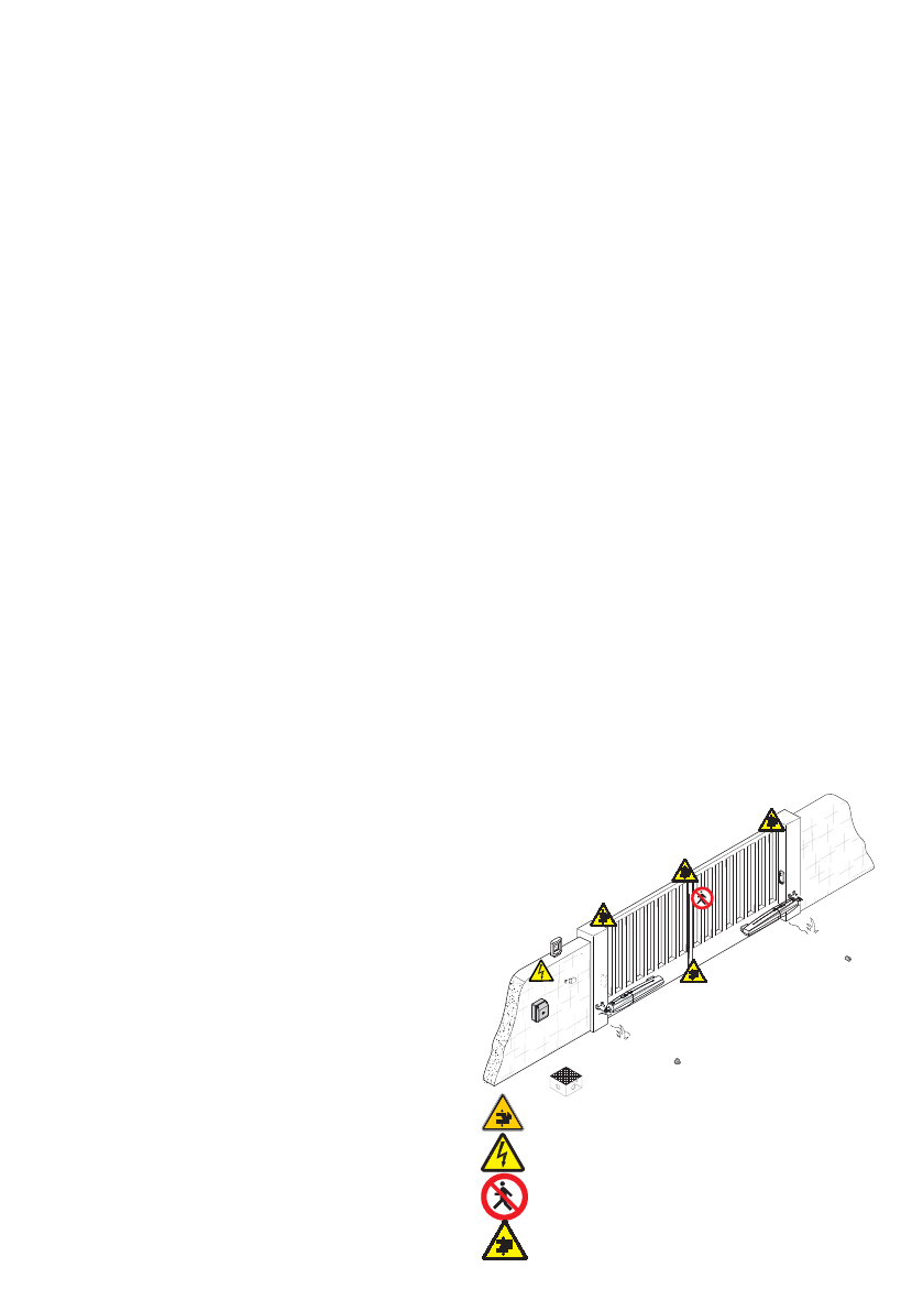
INSTALLING
• SUITABLY SECTION OFF AND DEMARCATE THE ENTIRE
INSTALLATION SITE TO PREVENT UNAUTHORIZED PERSONS
FROM ENTERING THE AREA, ESPECIALLY MINORS AND
CHILDREN • BE CAREFUL WHEN HANDLING GEARMOTORS
THAT WEIGH OVER 20 KG. IFNEED BE, USE PROPER SAFETY
HOISTING EQUIPMENT • ALL OPENING COMMANDS (THAT
IS, BUTTONS, KEY SWITCHES, MAGNETIC READERS, AND
SO ON) MUST BE INSTALLED AT LEAST 1.85 M FROM
THE PERIMETER OF THE GATE'SWORKING AREA, OR WHERE
THEY CANNOT BE REACHED FROM OUTSIDE THE GATE. ALSO,
ANY DIRECT COMMANDS (BUTTONS, TOUCH PANELS, AND
SO ON) MUST BE INSTALLED AT LEAST 1.5 MFROM THE
GROUND AND MUST NOT BE REACHABLE BY UNAUTHORIZED
PERSONS • ALL MAINTAINED ACTION COMMANDS, MUST BE
FITTED IN PLACES FROM WHICH THE MOVING GATE LEAVES
AND TRANSIT AND DRIVING AREAS ARE VISIBLE • APPLY, IF
MISSING, APERMANENT SIGN SHOWING THE POSITION OF THE
RELEASE DEVICE • BEFORE DELIVERING TO THE USERS, MAKE
SURE THE SYSTEM IS EN 12453 STANDARD COMPLIANT
(REGARDING IMPACT FORCES), AND ALSO MAKE SURE THE
SYSTEM HAS BEEN PROPERLY ADJUSTED AND THAT ANY
SAFETY, PROTECTION AND MANUAL RELEASE DEVICES ARE
WORKING PROPERLY • APPLY WARNING SIGNS (SUCH AS THE
GATE'SPLATE) WHERE NECESSARY AND IN AVISIBLE PLACE
SPECIAL USER-INSTRUCTIONS AND RECOMMENDATIONS
• KEEP GATE OPERATION AREAS CLEAN AND FREE OF
ANY OBSTRUCTIONS. MAKE SURE THAT THE PHOTOCELLS
ARE FREE OF ANY OVERGROWN VEGETATION AND THAT
THE GEARMOTOR'SAREA OF OPERATION IS FREE OF ANY
OBSTRUCTIONS • DO NOT ALLOW CHILDREN TO PLAY WITH
FIXED COMMANDS, OR TO LOITER IN THE GATE'SMANEUVERING
AREA. KEEP ANY REMOTE CONTROL TRANSMITTERS OR
ANY OTHER COMMAND DEVICE AWAY FROM CHILDREN,
TO PREVENT THE GEARMOTOR FROM BEING ACCIDENTALLY
ACTIVATED. • THE APPARATUS MAY BE USED BY CHILDREN
OF EIGHT YEARS AND ABOVE AND BY PHYSICALLY, MENTALLY
AND SENSORIALLY CHALLENGED PEOPLE, OR EVEN ONES
WITHOUT ANY EXPERIENCE, PROVIDED THIS HAPPENS UNDER
CLOSE SUPERVISION OR ONCE THEY HAVE BEEN PROPERLY
INSTRUCTED TO USE THE APPARATUS SAFELY AND ABOUT
THE POTENTIAL HAZARDS INVOLVED. CHILDREN MUST NOT
PLAY WITH THE APPARATUS. CLEANING AND MAINTENANCE
BY USERS MUST NOT BE DONE BY CHILDREN, UNLESS
PROPERLY SUPERVISED • FREQUENTLY CHECK THE SYSTEM
FOR ANY MALFUNCTIONS OR SIGNS OF WEAR AND TEAR OR
DAMAGE TO THE MOVING STRUCTURES, TO THE COMPONENT
PARTS, ALL ANCHORING POINTS, INCLUDING CABLES AND
ANY ACCESSIBLE CONNECTIONS. KEEP ANY HINGES, MOVING

p.
3
- Manual code:
FA00021-EN
FA00021-EN v.
4
11/2016 © CAME S.p.A. The contents of this manual may be changed at any time without prior notice.
DANGER OF HAND CRUSHING
DANGER! HIGH VOLTAGE.
NOTRANSITING WHILE THE BARRIER IS MOVING
DANGER OF FOOT CRUSHING
JOINTS AND SLIDE RAILS PROPERLY LUBRICATED • PERFORM
FUNCTIONAL CHECKS ON THE PHOTOCELLS AND SENSITIVE
SAFETY EDGES, EVERY SIX MONTHS. TOCHECK WHETHER
THE PHOTOCELLS ARE WORKING, WAVE AN OBJECT IN FRONT
OF THEM WHILE THE GATE IS CLOSING; IF THE GEARMOTOR
INVERTS ITS DIRECTION OF TRAVEL OR SUDDENLY STOPS, THE
PHOTOCELLS ARE WORKING PROPERLY. THIS IS THE ONLY
MAINTENANCE OPERATION TO DO WITH THE POWER ON.
CONSTANTLY CLEAN THE PHOTOCELLS' GLASS COVERS USING
ASLIGHTLY WATER-MOISTENED CLOTH; DO NOT USE ANY
SOLVENTS OR OTHER CHEMICAL PRODUCTS THAT MAY RUIN
THE DEVICES • IF REPAIRS OR MODIFICATIONS ARE REQUIRED
TO THE SYSTEM, RELEASE THE GEARMOTOR AND DO NOT USE
IT UNTIL SAFETY CONDITIONS HAVE BEEN RESTORED • CUT
OFF THE POWER SUPPLY BEFORE RELEASING THE GEARMOTOR
FOR MANUAL OPENINGS AND BEFORE ANY OTHER OPERATION,
TO PREVENT POTENTIALLY HAZARDOUS SITUATIONS. READ THE
INSTRUCTIONS • IF THE POWER SUPPLY CABLE IS DAMAGED, IT
MUST BE REPLACED BY THE MANUFACTURER OR AUTHORIZED
TECHNICAL ASSISTANCE SERVICE, OR IN ANY CASE, BY
SIMILARLY QUALIFIED PERSONS, TO PREVENT ANY RISK • IT IS
FORBIDDEN FOR USERS TO PERFORM ANY OPERATIONS THAT
ARE NOT EXPRESSLY REQUIRED OF THEM AND WHICH ARE NOT
LISTED IN THE MANUALS. FOR ANY REPAIRS, MODIFICATIONS
AND ADJUSTMENTS AND FOR EXTRAORDINARY MAINTENANCE,
CALL TECHNICAL ASSISTANCE • LOG THE JOB AND CHECKS
INTO THE PERIODIC MAINTENANCE LOG.
ADDITIONAL SPECIAL RECOMMENDATIONS FOR EVERYONE
• KEEP AWAY FROM HINGES AND MECHANICAL MOVING
PARTS • DO NOT ENTER THE GEARMOTOR'SAREA OF
OPERATION WHEN IT IS MOVING • DO NOT COUNTER THE
GEARMOTOR'SMOVEMENT AS THIS COULD RESULT IN
DANGEROUS SITUATIONS • ALWAYS PAY SPECIAL ATTENTION
TO ANY DANGEROUS POINTS, WHICH HAVE TO BE LABELED
WITH SPECIFIC PICTOGRAMS AND/OR BLACK AND YELLOW
STRIPES • WHILE USING ASELECTOR SWITCH OR A
COMMAND IN MAINTAINED ACTIONS, KEEP CHECKING THAT
THERE ARE NO PERSONS WITHIN THE OPERATING RANGE OF
ANY MOVING PARTS, UNTIL THE COMMAND IS RELEASED •
THE GATE MAY MOVE AT ANY TIME AND WITHOUT WARNING •
ALWAYS CUT OFF THE POWER SUPPLY BEFORE PERFORMING
ANY MAINTENANCE OR CLEANING.

0
50
100
150
200
250
300
350
1 1,25 1,5 1,75 2 2,25 2,5 2,75
SWN20
SWN25
p.
4
- Manual code:
FA00021-EN
FA00021-EN v.
4
11/2016 © CAME S.p.A. - The manual's contents may be edited at any time without notice.
DESCRIPTION
Encoder-fitted irreversible gearmotor for swing gates.
Aluminium and ABS cover, worm screw based reduction system, crown and conical torque.
Intended use
This gearmotor is designed to power and operate swing gates in private homes and apartment blocks.
Any installation other than what is detailed in this manual is prohibited.
LEGEND
This symbol shows which parts to read carefully.
⚠This symbol shows which parts describe safety issues
☞This symbol shows which parts to tell users about.
It always advisable to fit an electric lock on swing gates. It makes for a more reliable closure.
Gate-leaf weight (Kg)
Gate-leaf length (m)
Limits to use

750
350
838
110
120
p.
5
- Manual code:
FA00021-EN
FA00021-EN v.
4
11/2016 © CAME S.p.A. The contents of this manual may be changed at any time without prior notice.
Technical data
Type SWN20 SWN25
Protection rating (IP) 44
Control panel power supply (V - 50/60 Hz) 230 AC
Power supply motor (V) 24 DC
Max draw (A) 5
Maximum power (W) 120
Duty cycle (%) 50
Opening time at 90° (s) 15*
Operating temperature (°C) -20 ÷ +55
Apparatus class 3
Reduction ration (i) 1/36
Thrust (N) 400 ÷ 2000
Weight (Kg) 5.5 6
*The weight of the gearmotor includes the brackets. The motor's net weight is xx Kg.
** The weight of the gearmotor includes the brackets. The motor's net weight is xx Kg.
Dimensions (mm)
* Smallest reference value with fastest travel and slowest slow-down speeds. The weight and type of door, the
gate's state of wear-and-tear and the geography can all vary the value.

CAME
⑤
②
①
④
M8 x 35
UNI 7474 M8
⑥
⑦
③
⑦
⑥
⑥
⑥
⑤
④
⑥
⑧
⑧
③
②
①
①
p.
6
- Manual code:
FA00021-EN
FA00021-EN v.
4
11/2016 © CAME S.p.A. - The manual's contents may be edited at any time without notice.
Description of parts
1. Gearmotor
2. Gate bracket and fastening screw
3. Post bracket and fastening screw
4. Bushing for post bracket
5. Release key
6. Cover 1
7. Cover 2
Standard installation
1. Gearmotor
2. Control panel
3. Transmitter
4. Key-switch selector
5. Flashing light
6. Photocells
7. Junction pit
8. Mechanical gate stops
GENERAL INSTRUCTIONS FOR INSTALLING
Only skilled, qualified staff must install this product.
Preliminary checks
⚠Before beginning, do the following:
• check that the gate is stable and that the hinges are in good working order and lubricated;
• check that distance C does not exceed the reference-table value;
• make sure there are opening and closing mechanical gate stops;
• make sure that the point where the gearmotor is fastened is protected from any impacts and that the surface
is solid enough.
• make sure you have set up a suitable dual-pole cut off device along the power supply that is compliant with the
installation rules. It should completely cut off the power supply according to category III surcharge conditions
(that is, with minimum contact openings of 3 mm);
• make sure that any connections inside the container (ones that ensure continuity to the protection circuit) are
fitted with additional insulation with respect to those of other electrical parts inside:
• set up suitable tubes and conduits for the electric cables to pass through, making sure they are protected from
any mechanical damage.

p.
7
- Manual code:
FA00021-EN
FA00021-EN v.
4
11/2016 © CAME S.p.A. The contents of this manual may be changed at any time without prior notice.
Tools and materials
Make sure you have all the tools and materials you will need for installing in total safety and in compliance with
applicable regulations. The figure shows some of the equipment installers will need.
Cable types and minimum thicknesses
Connection Cable type Cable length
1 < 15 m
Cable length
15 < 30 m
Control panel power supply 230 V AC H05RN-F 3G x 1.5 mm23G x 2.5 mm2
Motor power supply 24 V DC
FROR CEI
20-22
CEI EN
50267-2-1
3 x 1 mm23 x 1.5 mm2
Flashing light 2 x 0.5 mm22 x 1 mm2
Photocell transmitters 2 x 0.5 mm22 x 0.5 mm2
Photocell receivers 4 x 0.5 mm24 x 0.5 mm2
Command and safety device 2 x 0.5 mm22 x 0.5 mm2
Antenna The RG58
antenna max 10 m
If cable lengths differ from those specified in the table, establish the cable sections depending on the actual
power draw of the connected devices and according to the provisions of regulation CEI EN 60204-1.
For multiple, sequential loads along the same line, the dimensions on the table need to be recalculated according
to the actual power draw and distances. For connecting products that are not contemplated in this manual, see the
literature accompanying said products
INSTALLATION
The following illustrations are mere examples in that the space for anchoring the gearmotor and accessories
varies depending on the installation area. It is up to the installer to find the most suitable solution.

E
≤60
41
100
p.
8
- Manual code:
FA00021-EN
FA00021-EN v.
4
11/2016 © CAME S.p.A. - The manual's contents may be edited at any time without notice.
⚠The greater the gate leaf's opening angle, the greater the opening speed and the slower is the gearmotor's thrust.
The smaller the gate leaf's opening angle, the slower the opening speed and the greater is the gearmotor's thrust.
Fastening the brackets
Establish the gate bracket fastening point and find the bracket's fastening point to the post, while respecting the
quotas shown in the drawings and tables.
Opening (°) A (mm) B (mm) C (mm) E (mm)
90 130 110 ÷ 170 0 ÷ 60 750
115 150 110 ÷ 160 0 ÷ 50 750
Laying the corrugated tubes
Set up the junction boxes and corrugated tubes you will
need to make connections coming from the junction
pit. To connect the gearmotor we suggest a Ø 60 mm
corrugated tube. Whereas for the accessories we
suggest Ø 25 mm tubes.
The number of tubes depends on the type of
system and the accessories you are going
to fit.

❶
❷
p.
9
- Manual code:
FA00021-EN
FA00021-EN v.
4
11/2016 © CAME S.p.A. The contents of this manual may be changed at any time without prior notice.
Lubricate the bushing and fit it into one of the holes on the post bracket.
Fasten the joint to the post bracket using the M8 x 35 bolt and UNI 7474 M8 nut.
Fastening the gearmotor
Fasten the bracket to the post ❶using suitable anchors and screws. If the post is made of metal, the bracket can
be welded to it.
Note: the holes on the bracket are for further opening angle variations of the gate leaf.
Fasten or weld the bracket to the gate ❷.

❸
❶
⚠
❷
p.
10
10 - Manual code:
FA00021-EN
FA00021-EN v.
4
11/2016 © CAME S.p.A. - The manual's contents may be edited at any time without notice.
Open the gate leaf(the grub screws on the mechanical stops are loose) and fit the pin into the gate bracket.
Fasten using the UNI6593 washer Ø 10 and the supplied UNI 5739 M10 X 10 bolt b.
Establishing the limit-switch points
⚠DO NOT REMOVE cover 1 without first sliding it.
Before establishing the endstop points, you need to: release the gearmotor (see paragraph on manually releasing
it) and remove covers 1 and 2 while carefully following the illustrations.

❹
⚠
❺
❻
p.
11
11 - Manual code:
FA00021-EN
FA00021-EN v.
4
11/2016 © CAME S.p.A. The contents of this manual may be changed at any time without prior notice.
⚠DO NOT REMOVE cover 2 without first sliding it.
For opening
Reach the gate leaf opening point you want and take
the mechanical stop to rest using the slide guide.
Fasten the closing mechanical stop's grub screws
.
For closing
Close the gate leaf completely and rest it against
the mechanical stop using the slide guide. Fasten
the closing mechanical stop's grub screws.
CONNECTIONS TO THE CONTROL PANEL

M2 N2 ENC2
M
E
A
M1 N1 ENC1
M2 N2 ENC2
M
M
p.
12
12 - Manual code:
FA00021-EN
FA00021-EN v.
4
11/2016 © CAME S.p.A. - The manual's contents may be edited at any time without notice.
Connection for opening outwards
⚠Establish the quotas Aand B.
Cut and fasten post bracket by supplementing it with an additional bracket (not issued).
Open the gate (max 90°), establish the quota Eand establish the gate bracket fastening point. Fasten the bracket.
Connecting two gearmotors
Connecting one gearmotor
Gearmotor with encoder (M2) 24 V DC
Gearmotor with encoder (M2) 24 V DC, delayed when closing.
Gearmotor with encoder (M1) 24 V DC, delayed when opening.
Opening (°) A (mm) B (mm) E (mm)
90 130 130 750

M1 N1 ENC1 M2 N2 ENC2
M
M
❻
⚠
❹
❺
❸
⚠
❶
❷
p.
13
13 - Manual code:
FA00021-EN
FA00021-EN v.
4
11/2016 © CAME S.p.A. The contents of this manual may be changed at any time without prior notice.
Make the necessary electrical connections as shown in the figure.
Gearmotor with encoder (M1) 24 V DC, delayed when
closing.
Gearmotor with encoder (M2) 24 V DC, delayed when
opening.
FINAL OPERATIONS
Fastening the covers
Once you have completed all electrical connections and commissioning, fit the covers as shown here
⚠YOU MUST first slide the covers forward and then snap them down into place.

❸
❷
❶
❸
❷
❶
p.
14
14 - Manual code:
FA00021-EN
FA00021-EN v.
4
11/2016 © CAME S.p.A. - The manual's contents may be edited at any time without notice.
LOCKING
⚠This procedure must be done with the main power cut off.
The gearmotor's manual release may cause unwanted movement of the gate, if the latter has any mechanical
issues or if it is not balanced.
RELEASING THE GEARMOTOR
RELEASING
PROBLEM POSSIBLE CAUSES FIXES AND REMEDIES
It neither opens
nor closes
• Power supply is missing
• The gearmotor is stuck
• The transmitter's battery is run down
• The transmitter is broken
• The stop button is either stuck or broken
• The opening/closing button or the key-switch
selector is stuck
• Check main power supply
• Call assistance
• Replace the batteries
• Call assistance
• Call assistance
• Call assistance
The gate opens
but does not
close
• The photocells are dirty • Clean and check proper working
state of photocells
• Call assistance
TROUBLESHOOTING

p.
15
15 - Manual code:
FA00021-EN
FA00021-EN v.
4
11/2016 © CAME S.p.A. The contents of this manual may be changed at any time without prior notice.
Date Notes Signature
MAINTENANCE
Periodic maintenance
☞Before doing any maintenance, cut off the power supply, to prevent any hazardous situations caused by
accidentally activating the gearmotor.
Periodic maintenance log kept by users (every six months)
Fitter's stamp Name of gearmotor
Job performed on (date)
Technician's signature
Requester's signature
Job performed
__________________________________________________________________
_____________________________________________________________________________
____________________________________________________________________________
Extraordinary maintenance
⚠The following table is for logging any extraordinary maintenance jobs, repairs and improvements performed
by specialized contractors.
Any extraordinary maintenance jobs must be done only by specialized technicians.
Extraordinary maintenance log
Fitter's stamp Name of gearmotor
Job performed on (date)
Technician's signature
Requester's signature
Job performed
__________________________________________________________________
_____________________________________________________________________________
____________________________________________________________________________

www. came.com
www. came.com
CAME S.p.A.
CAME S.p.A.
Via Martiri Della Libertà, 15 Via Cornia, 1/b - 1/c
31030
Dosson di Casier
Dosson di Casier
Treviso
Treviso - Italy
33079
Sesto al Reghena
Sesto al Reghena
Pordenone
Pordenone - Italy
(+39) 0422 4940
(+39) 0422 4941
(+39) 0434 698111
(+39) 0434 698434
p.
16
16 - Manual code:
FA00021-EN
FA00021-EN v.
4
11/2016 © CAME S.p.A.
The manual's contents may be edited at any time without notice.
DISMANTLING AND DISPOSAL
☞CAME S.p.A. applies a certified Environmental Management System at its premises, which is compliant with
the UNI EN ISO 14001 standard to ensure the environment is safeguarded.Please continue safeguarding the
environment. At CAME we consider it one of the fundamentals of our operating and market strategies. Simply follow
these brief disposal guidelines:
DISPOSING OF THE PACKAGING
The packaging materials (cardboard, plastic, and so on) should be disposed of as solid urban waste, and simply
separated from other waste for recycling. Always make sure you comply with local laws before dismantling and
disposing of the product.
DO NOT DISPOSE OF IN NATURE!
DISMANTLING AND DISPOSAL
Our products are made of various materials. Most of these (aluminum, plastic, iron, electrical cables) are classified
as solid household waste. They can be recycled by separating them before dumping at authorized city plants.
Whereas other components (control boards, batteries, transmitters, and so on) may contain hazardous pollutants.
These must therefore be disposed of by authorized, certified professional services. Before disposing, it is always
advisable to check with the specific laws that apply in your area.
DO NOT DISPOSE OF IN NATURE!
Fitter's stamp Name of gearmotor
Job performed on (date)
Technician's signature
Requester's signature
Job performed
_____________________________________________________________________
________________________________________________________________________________
_______________________________________________________________________________
_____________________
REFERENCE REGULATIONS
The product complies to the reference regulations in effect.
This manual suits for next models
1
Table of contents
Other CAME Garage Door Opener manuals

CAME
CAME BX Series User manual

CAME
CAME C-BX User manual

CAME
CAME BK241 User manual

CAME
CAME PRATICO SYSTEM BX Series User manual

CAME
CAME v6000 Guide

CAME
CAME V700E User manual

CAME
CAME BK-2200T User manual

CAME
CAME FROG-PM4 User manual

CAME
CAME 8K01MB-0576 STYLO KIT User manual

CAME
CAME VER-PLUS Series User manual