1
Contents
1. Read first and then … ..........................................................................1
2. Scope of supply ....................................................................................1
3. Brief description ....................................................................................1
4. Overview of the parts ............................................................................1
5. Technical data .......................................................................................2
6. Mounting ...............................................................................................2
7. Electrical connections ...........................................................................2
8. Configuring the isolating amplifier ........................................................3
9. Accessories and spare parts ................................................................3
10. Commissioning .....................................................................................3
11. Maintenance .........................................................................................3
12. Releasing the isolating amplifier ...........................................................3
13. Dimensional drawings ...........................................................................4
14. Declaration of conformity ......................................................................4
1. Read first and then …
The proper and safe operation of the device assumes that the
Operating Instructions are read and the safety warnings given
in the various Sections
6. Mounting
7. Electrical connections
8. Configuring the isolating amplifier
10. Commissioning
are observed.
Unauthorized repair or alteration of the unit invalidates the warranty!
The device should only be handled by appropriately trained personnel who
are familiar with it and authorised to work in electrical installations.
2. Scope of supply (Fig. 1 and 2)
Isolating amplifier
Order Code: Significance of the 1st to 5th digits
Description Order Code
1. Mechanical design 809 -
Housing with screw terminals, not pluggable 3
Housing with screw terminals, pluggable 9
2. Version/Power supply
Standard/Power supply 24 … 60 V DC, AC 1
Standard/Power supply 85 … 230 V DC, AC 2
[EEx ia] IIC/Power supply 24 … 60 V DC, AC 3
[EEx ia] IIC/Power supply 85…110 V DC/230 V AC 4
3. Current input rating
Input current max. final value 100 mA (standard) 1
Input current max. final value 1.5 mA 2
4. Alarm function
Without alarm function 0
With built-in alarm relay 1
Programmable
isolating amplifier
SINEAX TV 809
TV 809 Be 147 802-01 02.06
Camille Bauer LTD
Aargauerstrasse 7
CH-5610 Wohlen/Switzerland
Phone +41 56 618 21 11
Fax +41 56 618 35 35
e-mail: info@camillebauer.com
http://www.camillebauer.com
Operating Instructions
The instruments must only be disposed of in the
correct way!
The following symbols in the Operating Instructions indicate safety
precautions which must be strictly observed:
Description Order Code
5. Test records
Without test records 0
With test records in German D
With test records in English E
Fig. 1 Fig. 2
1 Operating Instructions (2) each in German, French and English
1 Ex approval (3), only for Ex version devices
3. Brief description
The purpose of the isolating amplifier SINEAX TV 809 is to electrically insulate
input and output signals, respectively to amplify and/or change the signal
level or type (current or voltage) of the input signals.
An explosion-proof “intrinsically safe” [EEx ia] IIC version rounds off this
series of SINEAX TV 809.
Measured variables and measuring ranges are programmed with the aid of a
PC, a programming cable and the programming software. Specific measured
variable data such as output signal, transmission characteristics and various
functions in combination with the alarm function can also be programmed.
Isolating amplifier supplied as standard versions are configured as follows:
– Measuring input:
– Measuring output:
– Response time:
– Mains ripple suppression:
4 … 20 mA
4 … 20 mA
80 ms
For frequency 50 Hz
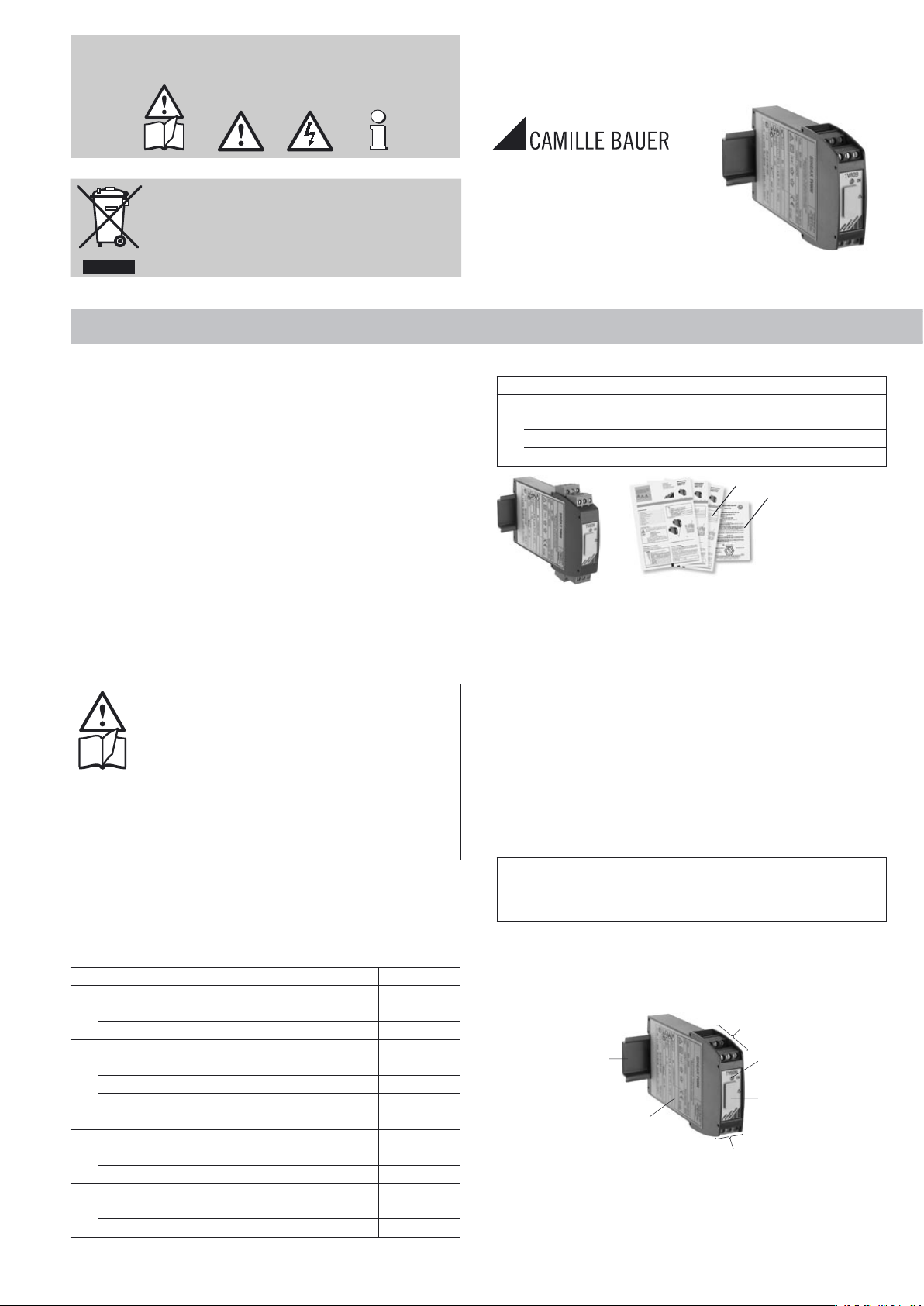
4. Overview of the parts
Figure 3 shows those parts of the device of consequence for electrical con-
nections and other operations described in the Operating Instructions.