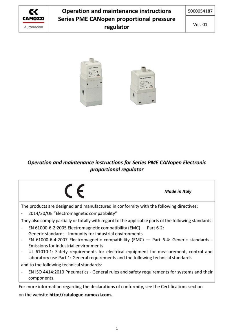
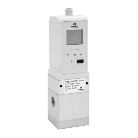
Camozzi PRE Series Manual

Operation and maintenance instructions
Series PRE proportional pressure regulator
IO-Link version
5000030186
Ver. 03
1
Operation and maintenance instructions for Series PRE Electronic proportional
regulator
The products are designed and manufactured in conformity with the following directives:
-2014/30/UE “Electromagnetic compatibility”
They also comply partially or totally with regard to the applicable parts of the following standards:
-EN 61000-6-2:2005 Electromagnetic compatibility (EMC) —Part 6-2:
Generic standards - Immunity for industrial environments
-EN 61000-6-4:2007 Electromagnetic compatibility (EMC) —Part 6-4: Generic standards -
Emissions for industrial environments
-UL 61010-1: Safety requirements for electrical equipment for measurement, control and
laboratory use Part 1: General requirements and the following technical standards
and to the following technical standards:
-EN ISO 4414:2010 Pneumatics - General rules and safety requirements for systems and their
components.
For more information regarding the declarations of conformity, see the Certifications section
on the website http://catalogue.camozzi.com.
Made in Italy

Operation and maintenance instructions
Series PRE proportional pressure regulator
IO-Link version
5000030186
Ver. 03
2
Table of contents
1. Product identification ..................................................................................................................4
2. Introduction .................................................................................................................................5
3. General recommendations ..........................................................................................................5
4. Product description:.....................................................................................................................6
5. Pneumatic symbol:.......................................................................................................................7
6. General characteristics and conditions of use.............................................................................8
7. Electrical/Pneumatic circuit.......................................................................................................16
8. Product storage and transport...................................................................................................16
9. Installation and start-up.............................................................................................................16
10. CoilVision.................................................................................................................................20
11. Universal visual interface X (UVIX)..........................................................................................20
11.1. Monitoring.......................................................................................................................20
11.2. Status information ..........................................................................................................21
11.3. Details..............................................................................................................................22
11.4. Configurator ....................................................................................................................23
11.5. USER SETUP .....................................................................................................................24
11.6. DIGITAL OUTPUT SETUP..................................................................................................25
11.7. PRESSURE SENSOR SETUP...............................................................................................25
12. Use...........................................................................................................................................25
13. IO-Link .....................................................................................................................................26
13.1. Cyclic data............................................................................................................................26
13.2. Acyclic data..........................................................................................................................27
13.2.1. Unit of measurement (pressure sensor) .........................................................................30
13.2.2. Minimum regulated pressure..........................................................................................30
13.2.3. Maximum regulated pressure .........................................................................................30
13.2.4. Pressure switch control ...................................................................................................30
13.2.5. Pressure window control.................................................................................................31
13.2.6. Lower limit switch control ...............................................................................................31
13.2.7. Upper limit switch control...............................................................................................31
13.2.8. Lower limit window control.............................................................................................31

Operation and maintenance instructions
Series PRE proportional pressure regulator
IO-Link version
5000030186
Ver. 03
3
13.2.9. Upper limit window control.............................................................................................31
13.2.10. Pressure regulation check mode .....................................................................................32
13.2.11. Pid mode..........................................................................................................................32
13.2.12. Pressure regulation check ...............................................................................................32
13.2.13. Pressure regulation timeout............................................................................................32
13.2.14. Charge coil health status .................................................................................................32
13.2.15. Discharge coil health status.............................................................................................32
13.2.16. Charge coil commands number.......................................................................................32
13.2.17. Discharge coil commands number ..................................................................................32
13.2.18. Charge coil maximum activation time.............................................................................32
13.2.19. Discharge coil maximum activation time ........................................................................33
13.2.20. Temperature....................................................................................................................33
13.2.21. Device Status ...................................................................................................................33
13.2.21.1. Detailed device status..................................................................................................33
13.2.22. Protection timeout ..........................................................................................................33
13.2.23. Pressure failsafe...............................................................................................................34
14. Block Parameters ....................................................................................................................34
15. Data Storage............................................................................................................................34
16. IO Device description (IODD) ..................................................................................................35
17. Troubleshooting and/or exceptional circumstances ..............................................................35
18. Limitations on use...................................................................................................................36
19. Maintenance ...........................................................................................................................36
20. Environmental notes...............................................................................................................37
21. Contacts ..................................................................................................................................38

Operation and maintenance instructions
Series PRE proportional pressure regulator
IO-Link version
5000030186
Ver. 03
4
1. Product identification

Operation and maintenance instructions
Series PRE proportional pressure regulator
IO-Link version
5000030186
Ver. 03
5
2. Introduction
This manual illustrates how to properly use the Series PRE electronic pressure regulator in its
version with IO-Link interface.
This version of the Controller is identified with code 0120 xx xx xxx x xxxxx, where 0120 indicates
the IO-Link version and is followed by year, week, machine, station and serial number.
For more information, refer to the manual dedicated to the Camozzi UVIX supervision software
(Universal Visual Interface X).
3. General recommendations
The recommendations regarding safe use in this document should be observed at all times.
•Some hazards can only be associated with the product after it has been installed on the
machine/equipment. It is the task of the final user to identify these hazards and reduced the
associated risks accordingly.
•The products dealt with in this manual may be used in circuits that must comply with the
standard EN ISO 13849-1.
•For information regarding component reliability, contact Camozzi.
•Before proceeding with use of the product, carefully read all information in this document.
•The instructions in this manual must be observed together with the instructions and
additional information regarding the product in this manual, available from the following
reference links:
oweb site http://www.camozzi.com
oCamozzi general catalogue
oTechnical assistance service
•Assembly and start-up operations must be performed exclusively by qualified and authorized
personnel on the basis of these instructions.
•It is the responsibility of the system/machine designer to ensure the correct selection of the
most suitable pneumatic component according to the intended application.
•For all situations not contemplated in this manual and in situations in which there is the risk
of potential damage to objects, or injury to persons or animals, contact Camozzi for advice.
•Never make unauthorized modifications to the product. In this case, any damage or injury
to objects, persons or animals will be the responsibility of the user.
•All relevant product safety standards must be observed at all times.
•Never intervene on the machine/system before verifying that all working conditions are safe.
•Before installation and maintenance, ensure that the specific envisaged safety locks are
active, and then disconnect the electrical mains (if necessary) and system pressure supply,
discharging all residual compressed air from the circuit and deactivating residual energy
stored in springs, condensers, recipients and gravity.

Operation and maintenance instructions
Series PRE proportional pressure regulator
IO-Link version
5000030186
Ver. 03
6
•To reduce the noise levels caused by the discharge of air from the component, envisage the
use of silencers or convey the fluid to a zone where no personnel are envisaged during
normal operation.
•Avoid covering the equipment with paint or other substances that may reduce heat
dissipation.
•Avoid cleaning with aggressive agents such as to dull the plastics and make it difficult to read
the screen
•In the event of an electrical power failure and pneumatic supply at the port connection 1,
the regulated pressure on port connection 2 will not be maintained and can be discharged.
4. Product description:
The Series PRE electronic pressure regulator is composed of:
•M12 4 pin connector (1): provides connection to power supply and communication with IO-
Link master (for more details refer to the paragraph “Installation and Commissioning").
•General diagnostic LED bar (3): provides a quick indication of the general status of the device
(for more details, refer to the "Use" paragraph).
•Micro USB connector (5) and wireless communication LED (4) to connect to the UVIX: the
device can be connected to the UVIX supervision software via wireless (if present) or USB
that allows to configure and monitor the device.
The configuration of some features of the Series PRE electronic pressure regulator is done
through the UVIX supervision software.
Two operating modes have been implemented:
•Automatic: the pressure target is set via the analog input. At startup the Regulator is in this
mode.
•Manual: the pressure target is set using the function keys or through a special command of
the UVIX supervision software. The regulator must be set in this mode during the
configuration phase in order to avoid unwanted pressure adjustments.

Operation and maintenance instructions
Series PRE proportional pressure regulator
IO-Link version
5000030186
Ver. 03
7
5. Pneumatic symbol:
Version with integrated
exhaust valve and external
servo-pilot supply
Version with integrated
exhaust valve and internal
servo-pilot supply
3 ways N.C. version with external
servo-pilot supply
3 ways N.C. version with internal
servo-pilot supply

Operation and maintenance instructions
Series PRE proportional pressure regulator
IO-Link version
5000030186
Ver. 03
8
6. General characteristics and conditions of use
General characteristics and conditions of use
PRE1
PRE2
Reference standards
CE; RoHs
Materials
Body: Aluminum Cover: Technopolymer Seal:NBR and FKM
Assembly position
Any
Overall dimensions
L = 50 mm; W = 50 mm; H = 140 mm
L = 50 mm; W = 50 mm; H = 185 mm
Weight
350gr circa
630gr circa
Medium and its quality
Filtered and non-lubricated compressed air of class 7.4.4 according to
ISO 8573.1. Inert gases and oxygen only for OX1 versions.
Maximum free flow rate
(Pin 10 bar)
Measured at ±5% of Preg
Pout 6 bar: 1.100 l/min ANR (PRE104)
Pout 4 bar: 1.200 l/min ANR (PRE104)
Pout 6 bar: 4.500 l/min ANR (PRE238)
Pout 4 bar: 5.200 l/min ANR (PRE238)
Maximum system
pressure drop
50 cc/min
10 cc/min
Maximun inlet pressure
(refer to coding table)
2 bar (B) 5 bar (E) 11 bar (D); (G) and (F)
Regulated pressure range
0 - 1 bar (0-14,5 PSI)(B) 0,05 - 10,3 bar (0,72-150 PSI)(D)
0,05 - 6 bar (0,72-87 PSI)(F) 0,03 - 4 bar (0,43-58 PSI) (E)
0,05 - 7 bar (0,72-101,5 PSI) (G)
Number of ways
3
Ambient temperature
0 ÷ 50 °C
Protection class
IP65 (according to EN 60529)
Open-type (according to UL 61010)
Pneumatic ports
Standard version: G1/4, 1/4 NPTF
Manifold version: G1/4; 1/4 NPTF
Standard version: G1/4, G3/8
Manifold version: G1/4
Vibrations sine
According to EN 60068 part
2-6:2009-11 (table B.1)
Frequency range: 10-500Hz
Displacement 0-peak: 0,75mm or 100 m/s2
Number of cycle: 10
Continuous shock
According to DIN EN
60068-2-27:2010-02 (table
A.1)
Peak acceleration: 150 m/s2
Duration: 11ms
Pulse shape: half sine
Electric port
M12 4 Pin Male A-key
Input signal setpoint
IO-Link
Electrical power supply
24Vdc ±10%

Operation and maintenance instructions
Series PRE proportional pressure regulator
IO-Link version
5000030186
Ver. 03
9
Current consumption
Max 0,250A (refer to the table below for more details)
Hysteresis (*)
0,5% FS
0,7% FS
Repeatability (*)
0,4% FS
0,4% FS
Linearity (*)
0,3% FS
0,3% FS
Resolution (*)
0,3% FS
0,6% FS
Overpressure discharge
With relieving
Modularity
With Series MD
(*) measured with Inlet pressure = Maximum regulated pressure + 1bar and a volume
connected to the outlet without any loss.
WIFI module
Integrated
exaust valve
Code
Maximum current
consumption
NO
NO
PRExxx-Ex5xxx-xx
PRExxx-Ex7xxx-xx
0,105 A
YES
NO
PRExxx-Ex5xxx-xxxW
PRExxx-Ex7xxx-xxxW
0,145 A
NO
YES
PRExxx-Ex6xxx-xx
PRExxx-Ex8xxx-xx
0,190 A
YES
YES
PRExxx-Ex6xxx-xxxW
PRExxx-Ex8xxx-xxxW
0,230 A

Operation and maintenance instructions
Series PRE proportional pressure regulator
IO-Link version
5000030186
Ver. 03
10
•Efficiency curve
y = 0,1033x
0
1
2
3
4
5
6
7
8
9
10
11
010 20 30 40 50 60 70 80 90 100
Regulated pressure [bar]
Electrical control signal [%]
Efficiency curve 10,33 bar
y = 0,04x
0
1
2
3
4
010 20 30 40 50 60 70 80 90 100
Regulated pressure [bar]
Electrical control signal [%]
Efficiency curve 4 bar

Operation and maintenance instructions
Series PRE proportional pressure regulator
IO-Link version
5000030186
Ver. 03
11
•FLOW CHARTS SIZE 1 - Standard version (1/4G)
Typical curve of flow rate from 0,2 to 1 bar
P = Regulated outlet pressure and exhaust pressure
Q = Flow
% = Percentage of the command signal
Inlet pressure 2 bar
Typical curve of flow rate from 0,5 to 4 bar
P = Regulated outlet pressure and exhaust pressure
Q = Flow
% = Percentage of the command signal
Inlet pressure 5 bar
Typical curve of flow rate from 0,5 to 6 bar
P = Regulated outlet pressure and exhaust pressure
Q = Flow
% = Percentage of the command signal
Inlet pressure 7 bar
Typical curve of flow rate from 0,5 to 7 bar
P = Regulated outlet pressure and exhaust pressure
Q = Flow
% = Percentage of the command signal
Inlet pressure 8 bar
Typical curve of flow rate from 1 to 9 bar
P = Regulated outlet pressure and exhaust pressure
Q = Flow
% = Percentage of the command signal
Inlet pressure 10 bar

Operation and maintenance instructions
Series PRE proportional pressure regulator
IO-Link version
5000030186
Ver. 03
12
•FLOW CHARTS SIZE 1 –Manifold version (1/4G)
Typical curve of flow rate from 0,2 to 1 bar
P = Regulated outlet pressure and exhaust pressure
Q = Flow
% = Percentage of the command signal
Inlet pressure 2 bar
Typical curve of flow rate from 0,5 to 4 bar
P = Regulated outlet pressure and exhaust pressure
Q = Flow
% = Percentage of the command signal
Inlet pressure 5 bar
Typical curve of flow rate from 0,5 to 6 bar
P = Regulated outlet pressure and exhaust pressure
Q = Flow
% = Percentage of the command signal
Inlet pressure 7 bar
Typical curve of flow rate from 0,5 to 7 bar
P = Regulated outlet pressure and exhaust pressure
Q = Flow
% = Percentage of the command signal
Inlet pressure 8 bar
Typical curve of flow rate from 1 to 9 bar
P = Regulated outlet pressure and exhaust pressure
Q = Flow
% = Percentage of the command signal
Inlet pressure 10 bar
DECAY FACTOR
N° = number of regulators in manifold configuration
D(%) = relative percentage decay of the maximum flow rate
Note: the air inlet is only from one side, in case it should be on the
right and on the left, only consider the positions as from 1 ÷ 3..

Operation and maintenance instructions
Series PRE proportional pressure regulator
IO-Link version
5000030186
Ver. 03
13
•FLOW CHARTS SIZE 2 - Standard version (1/4G)
Typical curve of flow rate from 0,2 to 1 bar
P = Regulated outlet pressure and exhaust pressure
Q = Flow
% = Percentage of the command signal
Inlet pressure 2 bar
Typical curve of flow rate from 0,5 to 4 bar
P = Regulated outlet pressure and exhaust pressure
Q = Flow
% = Percentage of the command signal
Inlet pressure 5 bar
Typical curve of flow rate from 0,5 to 6 bar
P = Regulated outlet pressure and exhaust pressure
Q = Flow
% = Percentage of the command signal
Inlet pressure 7 bar
Typical curve of flow rate from 0,5 to 7 bar
P = Regulated outlet pressure and exhaust pressure
Q = Flow
% = Percentage of the command signal
Inlet pressure 8 bar
Typical curve of flow rate from 1 to 9 bar
P = Regulated outlet pressure and exhaust pressure
Q = Flow
% = Percentage of the command signal
Inlet pressure 10 bar

Operation and maintenance instructions
Series PRE proportional pressure regulator
IO-Link version
5000030186
Ver. 03
14
•FLOW CHARTS SIZE 2 - Standard version (3/8G)
Typical curve of flow rate from 0,2 to 1 bar
P = Regulated outlet pressure and exhaust pressure
Q = Flow
% = Percentage of the command signal
Inlet pressure 2 bar
Typical curve of flow rate from 0,5 to 4 bar
P = Regulated outlet pressure and exhaust pressure
Q = Flow
% = Percentage of the command signal
Inlet pressure 5 bar
Typical curve of flow rate from 0,5 to 6 bar
P = Regulated outlet pressure and exhaust pressure
Q = Flow
% = Percentage of the command signal
Inlet pressure 7 bar
Typical curve of flow rate from 0,5 to 7 bar
P = Regulated outlet pressure and exhaust pressure
Q = Flow
% = Percentage of the command signal
Inlet pressure 8 bar
Typical curve of flow rate from 1 to 9 bar
P = Regulated outlet pressure and exhaust pressure
Q = Flow
% = Percentage of the command signal
Inlet pressure 10 bar

Operation and maintenance instructions
Series PRE proportional pressure regulator
IO-Link version
5000030186
Ver. 03
15
•Step response (Values determined according to ISO 10094-1)
PRE-104
Type of Dynamic tests
Dynamic Characteristics
No tank
Volume 0,4L
Volume 2L
Step 0% to 100%
Shifting Time [ms]
36
82
175
Response Time [ms]
260
372
1.261
Settling Time [ms]
179
247
934
Step 100% to 0%
Shifting Time [ms]
39
64
177
Response Time [ms]
678
957
4.152
Settling Time [ms]
470
708
3.170
PRE-238
Type of Dynamic tests
Dynamic Characteristics
No tank
Volume 0,4L
Volume 2L
Step 0% to 100%
Shifting Time [ms]
60
60
95
Response Time [ms]
350
465
850
Settling Time [ms]
250
325
650
Step 100% to 0%
Shifting Time [ms]
60
60
80
Response Time [ms]
850
860
870
Settling Time [ms]
600
590
565

Operation and maintenance instructions
Series PRE proportional pressure regulator
IO-Link version
5000030186
Ver. 03
16
7. Electrical/Pneumatic circuit
8. Product storage and transport
•Adopt all measures possible to avoid accidental damage to the product during transport, and
when available use the original packaging.
•Observe the specified storage temperature range of -20 ÷ 50 °C.
9. Installation and start-up
•During unpacking, take great care not to damage the product.
•Check whether there are any faults caused by product transport or storage.
•Separate all packaging material to enable the recovery or disposal in accordance with current
standards in the country of use.
•Where possible avoid the risk of repeated pressure surges on the circuit where the
component is installed.
•The components must be fixed correctly using, where possible, the specific brackets and
ensuring that the fixture remains efficient even when the actuator is repeatedly used at a
high frequency and in the presence of strong vibrations.
•Once the component is installed, ensure that all air ways are securely connected to the
respective couplings.
•If the power supply is turned off, residual pressure may remain on the secondary side of the
regulators. The manufacturer must provide for additional exhaust components.
Recommended pneumatic circuit
•Keep the protective cap of the M12 connector until the regulator is completely installed

Operation and maintenance instructions
Series PRE proportional pressure regulator
IO-Link version
5000030186
Ver. 03
17
•PRE series electronic regulator can be connected to DIN rails using the relative elements PCF-
E520 fitted on the rear of the body using two M4 threaded holes.
•The Series PRE electronic regulator can be directly fixed to a support using the 2 through
holes with diameter 4mm present on the body (not available in the PRE1 manifold version).
•The PRE1 electronic regulator can be fixed to the wall with the optional bracket code MD1-
ST/1 (if the two through holes in the body have a 34 mm center distance) or with the optional
bracket code PRE-ST (if the two through holes in the body have a 42 mm center distance);
the PRE2 electronic regulator can be fixed to the wall with the optional bracket code PRE-ST:
1. Fix the bracket to the wall with suitable screws
2. Connect the fittings G1/4; G3/8 or NPTF according to the PRE regulator size
3. Connect the regulator to the bracket with the two M4 x 55 screws supplied
•Make sure that the bracket is completely resting on the wall
•Connection of Manifold regulators with related Kit PRE-M-Pin-1-2
1. Insert the pins (1) in the seats on the regulator body
2. Insert the O-ring seal (3) into the special seat on the side face of the body
3. Bring the two modules sideways up until contact

Operation and maintenance instructions
Series PRE proportional pressure regulator
IO-Link version
5000030186
Ver. 03
18
4. Tighten the four grub screws (2) until they are locked (Tightening torque: 2,5 ± 0,5 Nm)
•There are 2 additional pneumatic ports on the PRE series electronic regulator:
oM5 to discharge the exhaust valve to the outside. It is important to keep this port
free and clean to ensure that air is discharged without obstructions that could limit
the flow. If necessary, remove the pre-assembled filter, connect a suitable coupling
and use a hose to convey discharged air to a suitable area.
oM5 for external servo-pilot supply. The regulator is supplied with a preassembled cap
for the versions with internal servo-pilot supply and with the fitting 6625 3-M5 for
the versions with external servo-pilot supply.
•In order to connect the regulator with MD series, use the PRE-1/4-C kit for regulator with
G1/4 pneumatic port or use the PRE-3/8-C kit for regulator with G3/8 pneumatic port.
•The board implements a protection against inversion of polarity on the power supply
voltage.
•The board is also fitted with a resettable 1A fuse to limit the maximum current absorption
of the servovalve. Use a power supply unit able to deliver a current of at least 0,5A
(recommended 1.0A).
•If UL/CSA standard compliance is required, the unit shall be supplied by an isolated power
source which fulfils at least one of the following the requirements of:
- Limited-Energy Circuit in accordance with UL/CSA 61010-1/ UL/CSA 61010-2-201
- Limited Power Source (LPS) in accordance with UL/CSA 60950-1
- a Class 2 supply source which complies with the National Electrical Code (NEC), NFPA 70,
Clause 725.121 and Canadian Electrical Code (CEC), Part I, C22.1. (typical examples are a
Class 2 transformer or a Class 2 power sources in compliance with, UL 5085-3/ CSA-C22.2
No. 66.3 or UL 1310/CSA-C22.2 No. 223). In order to respect the UL/CSA 61010
requirements, install the regulator inside a box, not in external environment.
•The power supply voltage must be within the range of 24V±10%.
•The board implements a protection against overload of the reference signal.
•The M12 4 pin male connector has the following pinout. The port is configured as port A:

Operation and maintenance instructions
Series PRE proportional pressure regulator
IO-Link version
5000030186
Ver. 03
19
•For the electrical connection the following cable types are available:
CODE
DESCRIPTION
CS-LF05HB-D200
co-moulded connector M12 5 pole, female, straight with 2-metre cable shielded
CS-LF05HB-D500
co-moulded connector M12 5 pole, female, straight with 5-metre cable shielded
CS-LR05HB-D200
co-moulded connector M12 5 pole, female, bend with 2-metre cable shielded
CS-LR05HB-D500
co-moulded connector M12 5 pole, female, bend with 5-metre cable shielded
G11W-G12W-2
Micro USB cable (it may be used during the configuration phase)
PIN
NAME
DESCRIPTION
1
L+
Power supply: Connect to the positive pole (24VDC) of the power supply.
2
N.C
Not connected.
3
L-
Power supply : Connect to the negative pole (GND) of the power supply.
4
C/Q
IO-Link communication

Operation and maintenance instructions
Series PRE proportional pressure regulator
IO-Link version
5000030186
Ver. 03
20
10.CoilVision
With the integrated CoilVision technology the proportional regulator is able to
constantly monitor the operation of the coils inside it and prevent any malfunctions.
Depending on the model chosen, the proportional regulator can have three different levels of
diagnostics:
•Without diagnostics: the CoilVision technology isn’t implemented.
•Basic diagnostics: CoilVision technology is active and will advise the user when the coils are
nearing the end of their life cycle
•CoilVision diagnostics: CoilVision technology is active and, in addition to advice the user
when the coils are nearing the end of their life cycle, constantly sends information about
their current health status to the UVIX environment.
11.Universal visual interface X (UVIX)
UVIX is a supervisor software that can be installed on PC or on server that is part of the company
network and accessible from other PCs.
UVIX communicates with the Series PRE electronic pressure regulator via wireless connection (if
present) or via USB cable and is able to monitor and configure the device.
Following the monitoring and configurator of the Series PRE electronic pressure regulator is
described in detail. For installation and use of the UVIX, please refer to the dedicated manual.
11.1. Monitoring
Once the device is selected, the work page will be displayed. This page is divided into two parts;
•Status information
•Details
Other manuals for PRE Series
2
This manual suits for next models
2
Table of contents
Other Camozzi Controllers manuals