vi
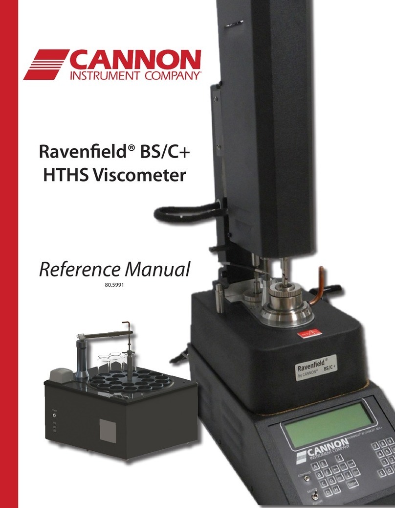
Ravenfield® BS/C+ Reference Manual
CANNON® Error! Reference source not found.
Figure 5: Lower shipping jig..................................................................................................................15
Figure 6: Upper shipping jig..................................................................................................................16
Figure 7: Connections at vacuum pump...............................................................................................17
Figure 8: Vacuum connections at instrument ......................................................................................17
Figure 9: Clean rotor and stator assembly ...........................................................................................20
Figure 10: Rotor and Stator assembly fitted (section view).................................................................21
Figure 11: Complete rotor and stator assembly...................................................................................23
Figure 12: Parts to be assembled for stator .........................................................................................24
Figure 13: Rotor and stator assembly ..................................................................................................25
Figure 14: Software Version .................................................................................................................28
Figure 15: Main Menu Screen ..............................................................................................................28
Figure 16: Constants Screen .................................................................................................................29
Figure 17: Rotor constants screen........................................................................................................29
Figure 18: Error/incorrect or incomplete data message......................................................................30
Figure 19: Reference Oil Table .............................................................................................................31
Figure 20: Shear Rate Screen................................................................................................................32
Figure 21: New Calibration Screen .......................................................................................................33
Figure 22: Calibration Screen ...............................................................................................................33
Figure 23: Cutoff screen .......................................................................................................................34
Figure 24: Adjust Gap Screen ...............................................................................................................35
Figure 25: Calibration Screen ...............................................................................................................36
Figure 26: Torque, temperature and speed screen..............................................................................37
Figure 27: Calibration complete screen................................................................................................38
Figure 28: Calibration table ..................................................................................................................39
Figure 29: Main menu screen...............................................................................................................40
Figure 30: Torque, temperature and speed .........................................................................................41
Figure 31: View Stored Data screen .....................................................................................................45
Figure 32: Set Up Instrument Constants sub-menu .............................................................................46
Figure 33: Calibrate LVDT screen..........................................................................................................47
Figure 34: Applying torque load ...........................................................................................................47
Figure 35: Position of 150 gm calibration weight.................................................................................48
