| ULTRAVIS Operation Manual
List of Figures
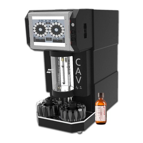
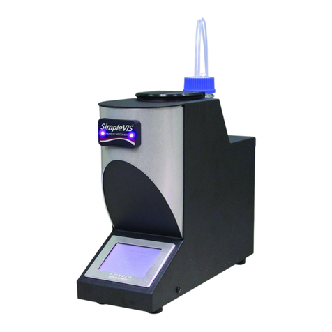
Figure 1 — UltraVIS 192 High Speed, Solvent-Free Kinematic Viscometer ........................................1
Figure 2 — UltraVIS Components......................................................................................................6
Figure 3 — Rear Connections with MAINS Power.............................................................................. 7
Figure 4 — Vacuum Pump Connections.............................................................................................7
Figure 5 — Vacuum Control Pump.....................................................................................................8
Figure 6 — Waste Receiver................................................................................................................8
Figure 7 — Backpack for Standards ...................................................................................................9
Figure 8 — At a Glance Screen ........................................................................................................10
Figure 9 — Control Gantry...............................................................................................................10
Figure 10 — Gantry Control Screen ................................................................................................. 11
Figure 11 — Calibrate Temperature................................................................................................. 11
Figure 12 — Adaptor Placement......................................................................................................12
Figure 13 — Cradle Placement.........................................................................................................12
Figure 14 — Insert Thermometer Probe ..........................................................................................12
Figure 15 — Inject Viscosity Standard N100..................................................................................... 13
Figure 16 — Edit Temperature Button............................................................................................. 13
Figure 17 — Enter Thermometer Temperature Reading.................................................................. 13
Figure 18 — UltraVIS Main Menu Screen/Select Settings ................................................................14
Figure 19 — UltraVIS Menu/Settings ............................................................................................... 15
Figure 20 — UltraVIS Menu/Settings/Standards.............................................................................. 15
Figure 21 — UltraVIS Add New Standard ........................................................................................16
Figure 22 —Name New Standard ....................................................................................................16
Figure 23 — Naming Standards Screen ........................................................................................... 17
Figure 24 — Standard Added .......................................................................................................... 17
Figure 25 — UltraVIS Main Menu Screen/Select Calibrate ...............................................................18
Figure 26 — Select Calibrate Viscometer ........................................................................................19
Figure 27 — Note C and E Constants ...............................................................................................19
Figure 28 — Select at Least Three Known Standards ......................................................................20
Figure 29 — Commit to Recalibrate Viscometer..............................................................................20
Figure 30 — Touchscreen Tray 1 Overview ......................................................................................21
Figure 31 — Sample Fill Line............................................................................................................22
Figure 32 — Choose Tray.................................................................................................................23
Figure 33 — Add Sample Group.......................................................................................................24
Figure 34 — Sample Name ..............................................................................................................24
Figure 35 — Starting Index ..............................................................................................................25
Figure 36 — Set Standard for Sample Group ...................................................................................25
Figure 37 — Select Standard for Sample Group...............................................................................26
Figure 38 — Multiple Sample Groups ..............................................................................................26
Figure 39 — Remove Samples ......................................................................................................... 27
