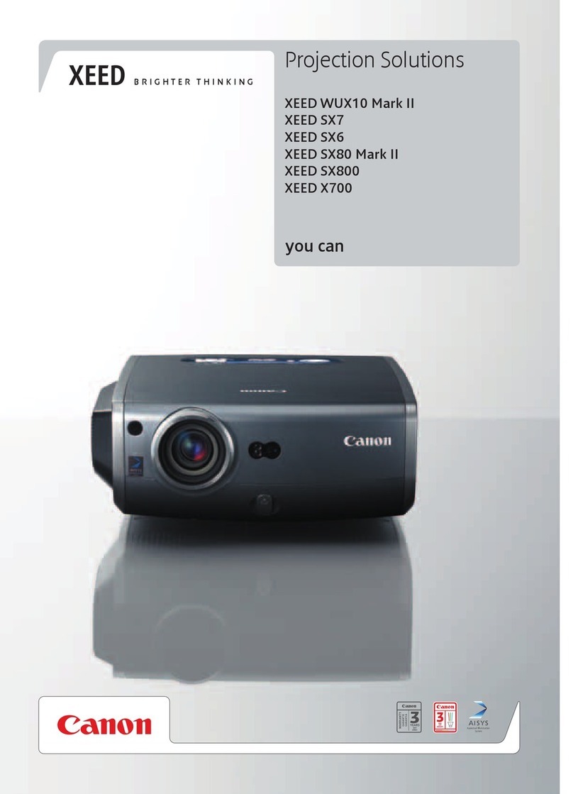
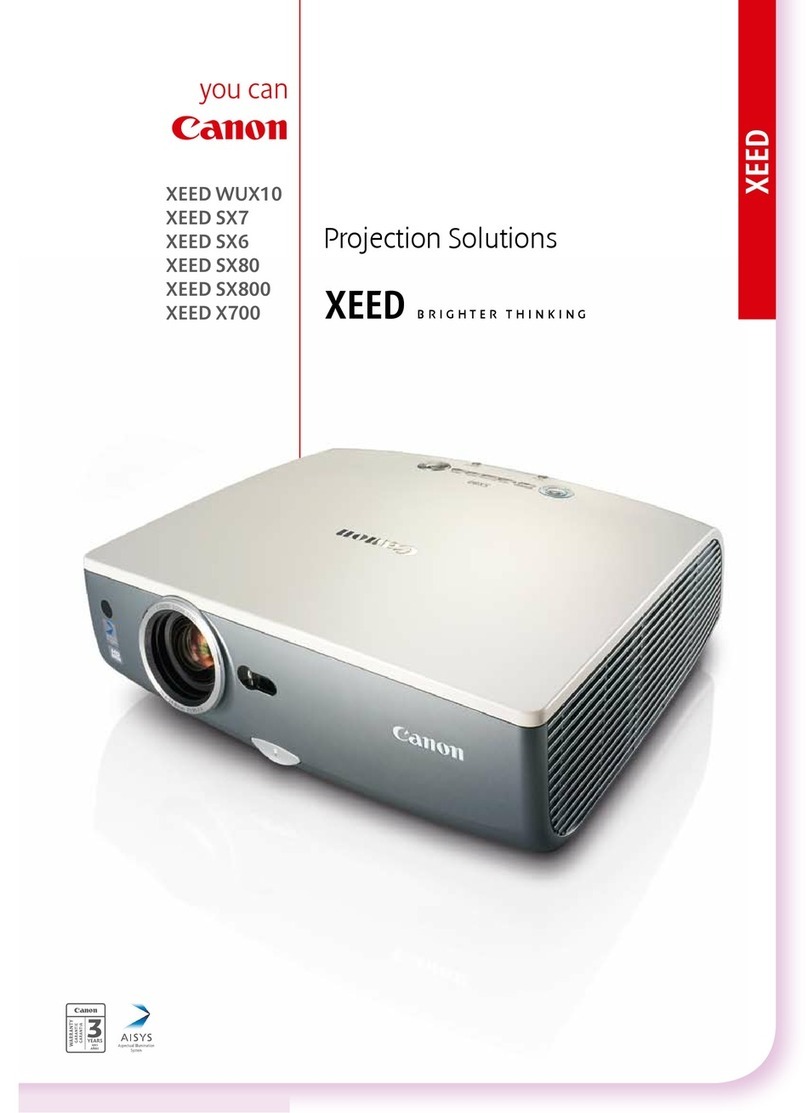
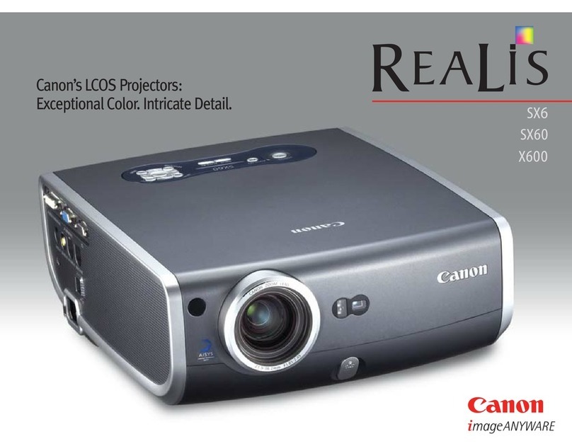
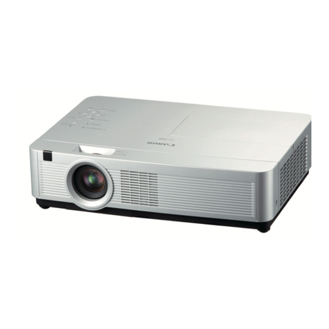
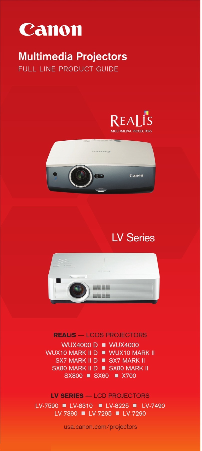
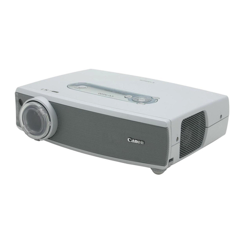
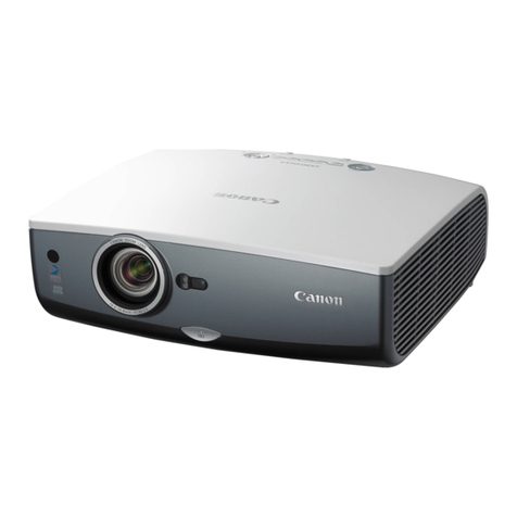
Canon LV-5220 - Multimedia Projector SVGA User manual

LV-7225/7220/5220
EXPAND SERIAL FUNCTIONAL SPECIFICATION
History of Modification
Rev. Contents Date Note
New Document 2004.08.31

Expand Serial Command Functional Specification Page 1 of 41
- CONTENT -
1. Overview ............................................................................................................................. 5
2. Serial Interface Specifications............................................................................................ 5
2.1. Communication Specification......................................................................................... 5
2.2. Connection ...................................................................................................................... 5
4. Notes for Notational ........................................................................................................... 6
5. Functional Execution Command Table .............................................................................. 7
5.1. Image Command Table................................................................................................... 7
5.2. PC Control Command Table ........................................................................................... 7
5.3. Video Control Command Table....................................................................................... 7
5.4. Input Control Command Table....................................................................................... 7
5.5. Screen Command Table .................................................................................................. 7
5.6. Lamp Command Table.................................................................................................... 8
5.7. Sound Command Table................................................................................................... 8
5.8. Setting Command Table ................................................................................................. 8
6. Status Read Command Table ............................................................................................. 9
6.1. Image Status Read Command Table .............................................................................. 9
6.2. PC Status Read Command Table ................................................................................... 9
6.3. Video Status Read Command Table ............................................................................... 9
6.4. Input Status Read Command Table ............................................................................... 9
6.5. Screen Status Read Command Table ............................................................................. 9
6.6. Lamp Status Read Command Table............................................................................... 9
6.7. Sound Status Read Command Table.............................................................................. 9
6.8. Setting Status Read Command Table .......................................................................... 10
6.9. Other Status Read Command Table............................................................................. 10
7. Error Code Table............................................................................................................... 10
8. Functional Execution Command ...................................................................................... 11
8.1. Format .......................................................................................................................... 11
8.2. Transfer Example ......................................................................................................... 11
8.3. Operation Requirements .............................................................................................. 11
8.4. Image Command........................................................................................................... 12
8.4.1. CF_BRIGHT Command ......................................................................................... 12
8.4.2. CF_CONT Command ............................................................................................. 12
8.4.3. CF_COLOR Command ........................................................................................... 12
8.4.4. CF_TINT Command............................................................................................... 12
8.4.5. CF_SHARP Command ........................................................................................... 13
8.4.6. CF_GAMMA Command.......................................................................................... 13
8.4.7. CF_WBAL- Command............................................................................................ 13
8.4.8. CF_COLTEMP Command ...................................................................................... 13
8.4.9. CF_PROGV Command ........................................................................................... 14
8.4.10. CF_FILM Command............................................................................................. 14
8.4.11. CF_IMAGE Command.......................................................................................... 14

Expand Serial Command Functional Specification Page 2 of 41
8.4.12. CF_IMAGEADJ Command .................................................................................. 14
8.5. PC Control Command................................................................................................... 15
8.5.1. CF_FSYNC Command ........................................................................................... 15
8.5.2. CF_TDOTS Command............................................................................................ 15
8.5.3. CF_CLAMP Command........................................................................................... 15
8.5.4. CF_H-POS Command............................................................................................. 15
8.5.5. CF_V-POS Command ............................................................................................. 16
8.5.6. CF_DDOTS Command ........................................................................................... 16
8.5.7. CF_DLINE Command ............................................................................................ 16
8.5.8. CF_PCSTORE Command....................................................................................... 17
8.5.9. CF_PCMODEFREE Command.............................................................................. 17
8.6. Video Control Command............................................................................................... 17
8.6.1. CF_AVDDOTS Command....................................................................................... 17
8.6.2. CF_AVDLINE Command ....................................................................................... 17
8.6.3. CF_AVHPOS Command ......................................................................................... 18
8.6.4. CF_AVVPOS Command ......................................................................................... 18
8.6.5. CF_AVSERV Command.......................................................................................... 18
8.7. Input Control Command............................................................................................... 18
8.7.1. CF_INPUT Command ............................................................................................ 18
8.7.2. CF_SOURCE Command......................................................................................... 19
8.7.3. CF_INPUT_%1_%2 Command............................................................................... 19
8.7.4. CF_SYSTEM Command......................................................................................... 20
8.8. Screen Control Command............................................................................................. 20
8.8.1. CF_SCREEN Command......................................................................................... 20
8.8.2. CF_FLSCREN Command....................................................................................... 21
8.8.3. CF_TRUE Command.............................................................................................. 21
8.8.4. CF_DZCENT Command......................................................................................... 21
8.8.5. CF_KEYSTONE Command.................................................................................... 21
8.8.6. CF_KYSTNMODE Command ................................................................................ 22
8.9. Lamp Command............................................................................................................ 22
8.9.1. CF_LAMPH Command .......................................................................................... 22
8.9.2. CF_LAMPMODE Command .................................................................................. 22
8.10. Sound Command......................................................................................................... 22
8.10.1. CF_VOLUME Command...................................................................................... 22
8.10.2. CF_MUTE Command........................................................................................... 23
8.11. Setting Command ....................................................................................................... 23
8.11.1. CF_BBACK Command ......................................................................................... 23
8.11.2. CF_DISP Command.............................................................................................. 23
8.11.3. CF_LOGO Command............................................................................................ 23
8.11.4. CF_CEIL Command ............................................................................................. 23
8.11.5. CF_REAR Command ............................................................................................ 24
8.11.6. CF_RCODE Command ......................................................................................... 24

Expand Serial Command Functional Specification Page 3 of 41
8.11.7. CF_LANG Command............................................................................................ 24
8.11.8. CF_ON-STA Command......................................................................................... 24
8.11.9. CF_P-MANE Command ....................................................................................... 25
8.11.10. CF_P-MANETIME Command............................................................................ 25
8.11.11. CF_FANSPEED Command................................................................................. 25
8.11.12. CF_KEYDIS Command ...................................................................................... 25
8.11.13. CF_TERMINAL Command ................................................................................ 25
8.11.14. CF_STANDBYMODE Command ....................................................................... 26
8.11.15. CF_POINTER Command ................................................................................... 26
8.11.16. CF_FDEFAULT Command................................................................................. 26
8.11.17. CF_AUTOSETUP Command.............................................................................. 26
8.11.18. CF_LOGOCAPTURE Command ........................................................................ 27
8.11.19. CF_FANMODE Command ................................................................................. 27
9. Status Read Command..................................................................................................... 28
9.1. Format .......................................................................................................................... 28
9.2. Transfer Example ......................................................................................................... 28
9.3. Operation Requirement ................................................................................................ 28
9.4. Image Status Read Command...................................................................................... 28
9.4.1. CR_BRIGHT Command ......................................................................................... 28
9.4.2. CR_CONT Command ............................................................................................. 28
9.4.3. CR_COLOR Command........................................................................................... 28
9.4.4. CR_TINT Command............................................................................................... 29
9.4.5. CR_SHARP Command ........................................................................................... 29
9.4.6. CR_GAMMA Command ......................................................................................... 29
9.4.7. CR_WBAL-R Command ......................................................................................... 29
9.4.8. CR_WBAL-G Command......................................................................................... 29
9.4.9. CR_WBAL-B Command ......................................................................................... 29
9.4.10. CR_COLTEMP Command.................................................................................... 30
9.4.11. CR_PROGV Command ......................................................................................... 30
9.4.12. CR_FILM Command ............................................................................................ 30
9.4.13. CR_IMAGE Command ......................................................................................... 30
9.4.14. CR_IMGGMD Command...................................................................................... 30
9.5. PC Status Read Command ........................................................................................... 31
9.5.1. CR_FSYNC Command ........................................................................................... 31
9.5.2. CR_TDOTS Command ........................................................................................... 31
9.5.3. CR_CLAMP Command........................................................................................... 31
9.5.4. CR_H-POS Command ............................................................................................ 31
9.5.5. CR_V-POS Command ............................................................................................. 31
9.5.6. CR_DDOTS Command........................................................................................... 32
9.5.7. CR_DLINE Command............................................................................................ 32
9.5.8. CR_PCSTORE Command....................................................................................... 32
9.5.9. CR_SETPCADJ Command..................................................................................... 32

Expand Serial Command Functional Specification Page 4 of 41
9.6. Video Status Read Command ....................................................................................... 33
9.6.1. CR_SERSYS Command.......................................................................................... 33
9.7. Input Status Read Command ....................................................................................... 33
9.7.1. CR_INPUT Command............................................................................................ 33
9.7.2. CR_SOURCE Command ........................................................................................ 33
9.7.3. CR_INPUT_%1 Command ..................................................................................... 34
9.7.4. CR_SYSTEM Command......................................................................................... 34
9.8. Screen Status Read Command ..................................................................................... 35
9.8.1. CR_SCREEN Command......................................................................................... 35
9.8.2. CR_FLSCREN Command ...................................................................................... 35
9.8.3. CR_TRUE Command ............................................................................................. 35
9.8.4. CR_KYSTNMODE Command................................................................................ 35
9.9. Lamp Status Read Command....................................................................................... 36
9.9.1. CR_LAMPREPL Command.................................................................................... 36
9.9.2. CR_LAMPMODE Command.................................................................................. 36
9.9.3. CR_PROJH Command ........................................................................................... 36
9.10. Sound Status Read Command.................................................................................... 36
9.10.1. CR_VOLUME Command ..................................................................................... 36
9.10.2. CR_MUTE Command........................................................................................... 36
9.11. Setting Status Read Command................................................................................... 37
9.11.1. CR_BBACK Command ......................................................................................... 37
9.11.2. CR_DISP Command ............................................................................................. 37
9.11.3. CR_LOGO Command ........................................................................................... 37
9.11.4. CR_RCODE Command......................................................................................... 37
9.11.5. CR_LANG Command............................................................................................ 38
9.11.6. CR_ON-STA Command......................................................................................... 38
9.11.7. CR_P-MANE Command ....................................................................................... 38
9.11.8. CR_P-MANETIME Command.............................................................................. 38
9.11.9. CR_FANSPEED Command .................................................................................. 38
9.11.11. CR_TERMINAL Command ................................................................................ 39
9.11.12. CR_STANDBYMODE Command ....................................................................... 39
9.11.13. CR_POINTER Command ................................................................................... 39
9.11.14. CR_AUTOSETUP Command ............................................................................. 40
9.11.15. CR_FANMODE Command ................................................................................. 40
9.12. Other Status Read Command..................................................................................... 40
9.12.1. CR_SIGNAL Command........................................................................................ 40
9.12.2. CR_VMUTE Command ........................................................................................ 40
9.12.3. CR_FREEZE Command ....................................................................................... 40
9.12.4. CR_PTIMER Command ....................................................................................... 41
9.12.5. CR_TEMPWARN Command ................................................................................ 41
9.12.6. CR_TEMPFAIL Command................................................................................... 41

Expand Serial Command Functional Specification Page 5 of 41
1. Overview
1.1. This Functional Specification defines communication functions such as Multi Card Imager for
LV-7225/7220/5220.
1.2. The Projector Firmware Ver.1.x ready.
1.3. Commands are to communicate to such as Multi Card Imager, but most commands control a
remote Projector with PC installed RS232C. That’s why commands are defined as expand serial
commands.
2. Serial Interface Specifications
2.1. Communication Specification
Item Specification
Synchro System Asynchronous
Transmission Speed 9600 / 19200
Data Length 8 bit
Parity N/A
Stop Bit 1
Flow Control N/A
1). Transfer rate: initial setting value is 19200.
2). Transfer rate can be changed by service mode.
2.2. Connection
Dedicated serial cable that comes with the Projector must be used for a connection to a computer and
a Projector.
PC Projector
COM 1 SERVICEPort
1
2
3
4
5
6
7
8
9
1
2
3
4
5
6
7
8
CD
SG
RXD
TXD
DTR
DSR
RTS
CTS
RING
(Dsub-9pin) (MiniDIN-8pin)

Expand Serial Command Functional Specification Page 6 of 41
3. Notes for Communication
3.1. The expand command is defined one command / one line that starts ”C” and ends carriage return
(0x0D).
3.2. There are two types of command, functional execution commands and state read commands.
Example of Functional Execution Command
“CF_BRIGHT_032” [CR]
Example of State Read Command
“CR_RIGHT” [CR]
Note) _ means a space
3.3. When it takes more than one second to receive on command, it clears information of buffer.
Since the Projector has received the first data “C”, when it takes more than 1 second until the
Projector receives a carriage return (0x0D), it clears information of buffer.
3.4. When a Computer keeps sending some command, it must wait sending next command after 100ms
when the Computer receives the return command.
More than 100ms
Command
PC →Projector “CF_BRIGHT_032” CR NextCommand
Projector →PC “000” CR
Response
(Afewms-5s)
3.4.1. When a computer sends next command before receiving a return command, the Projector may
not operate properly.
3.4.2. When there is no response after 5 seconds, issue next command.
3.5. It takes about 5 seconds for internal initialization after plugging in AC.
During this time, it cannot process command. Do not issue any commands.
4. Notes for Notational
4.1. Data from a controller to a Projector is represented as COMMAND, and data from a Projector to a
controller for the incoming command is represented as RESPONSE.
4.2. [CR]: Carriage Return code
The Command ends carriage return code. Also response Command ends carriage return, too.
4.3. _: Space Code
All space code is indicated by (_).
4.4. %1: Parameter in Command
When there are some parameters, the parameters are defined as %2, %3…
4.5. %%%: Error Code from a Projector
“000”: Normal Reception
See “5. Error Code Table“ for error number.
4.6. %a: Parameter for response from a Projector.
When there are a few parameters, the parameter defines as %b, %c…

Expand Serial Command Functional Specification Page 7 of 41
5. Functional Execution Command Table
5.1. Image Command Table
Execute command Item
CF_BRIGHT_%1 [CR] Set Brightness value
CF_CONT_%1 [CR] Set Contrast value
CF_COLOR_%1 [CR] Set Color value
CF_TINT_%1 [CR] Set Tint value
CF_SHARP_%1 [CR] Set Sharpness value
CF_GAMMA_%1 [CR] Set Gamma value
CF_WBAL-R_%1 [CR] Set White Balance Red value
CF_WBAL-G_%1 [CR] Set White Balance Green value
CF_WBAL-B_%1 [CR] Set White Balance Blue value
CF_COLTEMP_%1 [CR] Set Color Temp. value
CF_PROGV_%1 [CR] Set or Cancel for Progressive
CF_FILM_%1 [CR] Set or Cancel for Film mode
CF_IMAGE_%1 [CR] Set Image mode
CF_IMAGEADJ_%1 [CR] Reset and Store for Image adjustment
5.2. PC Control Command Table
Execute command Item
CF_FSYNC_%1 [CR] Set Fine Sync value
CF_TDOTS_%1 [CR] Set Total Dots value
CF_CLAMP_%1 [CR] Set Clamp value
CF_H-POS_%1 [CR] Set Horizontal Position value
CF_V-POS_%1 [CR] Set Vertical Position value
CF_DDOTS_%1 [CR] Set Display Dots value
CF_DLINE_%1 [CR] Set Display Line value
CF_PCSTORE_%1 [CR] Store current PC Adj. status to Mode1, 2, 3, 4, or 5
CF_PCMODEFREE_%1 [CR] Reset Mode1, 2, 3, 4, and 5
5.3. Video Control Command Table
Execute command Item
CF_AVDDOTS_%1 [CR] Set Horizontal Resolution value
CF_AVDLINE_%1 [CR] Set Vertical Resolution value
CF_AVHPOS_%1 [CR] Set Horizontal Position value
CF_AVVPOS_%1 [CR] Set Vertical Position value
CF_AVSERV_%1 [CR] Reset Horizontal / Vertical Resolution that are set in
such as CF_AVDDOTS / CF_AVDLINE to default setting.
5.4. Input Control Command Table
Execute command Item
CF_INPUT_%1 [CR] Select Input
CF_SOURCE_%1 [CR] Select Input Sauce
CF_INPUT_%1_%2 [CR] Select Input and Source
CF_SYSTEM_%1 [CR] Select System
5.5. Screen Command Table
Execute command Item
CF_SCREEN_%1 [CR] Select Screen size
CF_FLSCREN_%1 [CR] Set and Cancel Full Screen
CF_TRUE_%1 [CR] Set and Cancel True for Screen
CF_DZCENT_%1 [CR] Cancel Digital Zooms
CF_KEYSTONE_%1 [CR] Set Keystone
CF_KYSTNMODE_%1 [CR] Set Keystone Store mode

Expand Serial Command Functional Specification Page 8 of 41
5.6. Lamp Command Table
Execute command Item
CF_LAMPH_%1 [CR] Reset Lamp total running time
CF_LAMPMODE_%1 [CR] Select Lamp mode
5.7. Sound Command Table
Execute command Item
CF_VOLUME_%1 [CR] Set Volume value
CF_MUTE_%1 [CR] Control Sound Mute On / Off
5.8. Setting Command Table
Execute command Item
CF_BBACK_%1 [CR] Set Blue Back function
CF_DISP_%1 [CR] Set Display function
CF_LOGO_%1 [CR] Set Logo function
CF_CEIL_%1 [CR] Set Ceiling function
CF_REAR_%1 [CR] Set Rear Function
CF_RCODE_%1 [CR] Select Remote Control Reception Code
CF_LANG_%1 [CR] Select OSD language
CF_ON-STA_%1 [CR] Set Power On Start Function
CF_P-MANE_%1 [CR] Set Power Management function
CF_P-MANETIME_%1 [CR] Set Power Management time
CF_FANSPEED_%1 [CR] Select Fan Speed
CF_KEYDIS_%1 [CR] RC / KEY inhibit
CF_TERMINAL_%1 [CR] Set Terminal
CF_STANDBYMODE_%1 [CR] Set Standby mode
CF_POINTER_%1_%2[CR] Set Pointer
CF_FDEFAULT_%1[CR] Set Factory Default
CF_AUTOSETUP_%1_%2[CR] Set Auto Setup
CF_LOGOCAPTURE_%1[CR] Capture the current image on the screen
CF_FANMODE_%1[CR] Select Fan mode

Expand Serial Command Functional Specification Page 9 of 41
6. Status Read Command Table
6.1. Image Status Read Command Table
Status read command Item
CR_BRIGHT [CR] Read Brightness setting value
CR_CONT [CR] Read Contrast setting value
CR_COLOR [CR] Read Color setting value
CR_TINT [CR] Read Tint setting value
CR_SHARP [CR] Read Sharpness setting value
CR_GAMMA [CR] Read Gamma setting value
CR_WBAL-R [CR] Read White Balance Red value
CR_WBAL-G [CR] Read White Balance Green value
CR_WBAL-B [CR] Read White Balance Blue value
CR_COLTEMP [CR] Read Color temperature setting
CR_PROGV [CR] Read Progressive setting
CR_FILM [CR] Read Film mode setting
CR_IMAGE [CR] Read Image mode setting
CR_IMGGMD [CR] Read Image-Gamma setting value
6.2. PC Status Read Command Table
Status read command Item
CR_FSYNC [CR] Read Fine Sync setting value
CR_TDOTS [CR] Read Total Dots setting value
CR_CLAMP [CR] Read Clamp setting value
CR_H-POS [CR] Read Horizontal Position setting value
CR_V-POS [CR] Read Vertical Position setting value
CR_DDOTS [CR] Read Display Dots setting value
CR_DLINE [CR] Read Display Line setting value
CR_PCSTORE [CR] Read Free or Store is selected for PC Adj.; Mode1-5
CR_SETPCADJ [CR] Read Current PC signal for PC display status
6.3. Video Status Read Command Table
Status read command Item
CR_SERSYS [CR] Read selected current signal. When in Auto mode, it returns
a result by Auto detect.
6.4. Input Status Read Command Table
Status read command Item
CR_INPUT [CR] Read selected Input
CR_SOURCE [CR] Read selected Input Source
CR_INPUT_%1 [CR] Read Input and the Source
CR_SYSTEM [CR] Read selected system status in Input mode
6.5. Screen Status Read Command Table
Status read command Item
CR_SCREEN [CR] Read selected screen size
CR_FLSCREN [CR] Read Full screen mode
CR_TRUE [CR] Read True mode setting
CR_KYSTNMODE [CR] Read Keystone Store mode setting
6.6. Lamp Status Read Command Table
Status read command Item
CR_LAMPREPL [CR] Read information for Lamp replacement time
CR_LAMPMODE [CR] Read Lamp mode status
CR_PROJH [CR] Read Projector total running time
6.7. Sound Status Read Command Table
Status read command Item
CR_VOLUME [CR] Read Volume Value
CR_MUTE [CR] Read Sound Mute setting

Expand Serial Command Functional Specification Page 10 of 41
6.8. Setting Status Read Command Table
Status read command Item
CR_BBACK [CR] Read Blue Back setting
CR_DISP [CR] Read Display setting
CR_LOGO [CR] Read Logo setting
CR_RCODE [CR] Read selected Remote Code
CR_LANG [CR] Read selected Language
CR_ON-STA [CR] Read On Start setting status
CR_P-MANE [CR] Read Power Management setting status
CR_P-MANETIME [CR] Read the start time for Power Management
CR_FANSPEED [CR] Read selected FAN Control Speed
CR_KEYDIS [CR] Read RC/KEY Prohibit status
CR_TERMINAL [CR] Read Terminal setting status
CR_STANDBYMODE [CR] Read Standby mode setting status
CR_POINTER [CR] Read Pointer setting status
CR_AUTOSETUP_%1 [CR] Read Auto Setup setting status
CR_FANMODE [CR] Read selected Fan mode
6.9. Other Status Read Command Table
Status read command Item
CR_SIGNAL [CR] Read the status if there is signal or no signal
CR_VMUTE [CR] Read No Show setting status
CR_FREEZE [CR] Read Freeze setting status
CR_PTIMER [CR] Read P-Timer operational status
CR_TEMPWARN [CR] Read if sensors are exceeding critical temperature or not
CR_TEMPFAIL [CR] Read the temperature when sensors approached critical
temperature
7. Error Code Table
Error Code Content
?
When receives data that cannot be decoded.
Parameter determination error. (Digit number error, and
incorrect letter included)
000 Normal Reception. (Not error)
101 The function is not available in the selected Mode.
102 Selected the value is out of range. (Selected value will not be
reflected)
103 Command mismatched to the Hardware. (Command for
unpopulated option function)
201 When sending command, the increment is maximum value or
the decrement is minimum value.
301 Processing image capture. Re-try it again later.
302 Processing Auto setup, not executable.
Re-try it again later.
303 Processing Memory Card Viewer. Re-try it again later.
402 Processing PIN Code, not executable.
Re-try it again later.
Note) this error code for Expand Command, not applicable for Basic Command.

Expand Serial Command Functional Specification Page 11 of 41
8. Functional Execution Command
8.1. Format
1) The following format’s commands issued form a PC.
Pattern 1: “CF_COMMAND” [CR]
Pattern 2: “CF_COMMAND_” %1 [CR]
CF_: Header
COMMAND: Letters
%1: Parameter (Letters)
_: Space (To separate COMMAND and Parameter)
2) When a projector decoded a received data and ready to receive the next Command, it will return
acknowledgment.
“000” [CR]: (0x06, 0x0D) When received Function Execute Command.
“nnn” [CR]: Unable to execute any value except “000” value for any specific reason.
See the Error Code Table for its contents
3) When received an undecodable data,
returns “?” [CR].
8.2. Transfer Example
When setting Projector Total Dots to 1344 by Expand Command
PC →Projector: “CF_TDOTS_1344” [CR]
Projector →PC: “000” [CR] ---------------------- Reception OK
8.3. Operation Requirements
When the Projector’s status in this below, functional execution commands are limited.
Status Read Commands are available even in this table status.
Projector Status Available Function Execution Command
Standby Mode C00: Power On
Processing Count Down C00: Power On
(Terminate Count Down)
Processing Cooling Down None
Cooling Down due to abnormal temperature None
Abnormal Temperature None
Abnormal Power
(60sECOnds after Power has turned to abnormal) None
Processing Power Save Cooling Down None
Processing Power Save C00: Power On
C01: Power Off
Note) When the Projector receives other commands in the above status; they return error code to
show the status.

Expand Serial Command Functional Specification Page 12 of 41
8.4. Image Command
8.4.1. CF_BRIGHT Command
Command “CF”_BRIGHT_%1” [CR]
%1
“000 – 063” ----------- Directly select the Bright setting value
“UP” -------------------- Bright setting value +1
“DN” -------------------- Bright setting value -1
Details
Set the user control Bright value.
The value set by the command will not be saved to the Projector.
Therefore, when AC Power Off the Projector, the value will return to the original
setting. (For Standby mode, this value stays)
Only valid when it is in the usual Power On state.
Acceptable “000” [CR]
Response
Unacceptable “Error Code” [CR]
8.4.2. CF_CONT Command
Command “CF_CONT_%1” [CR]
%1
“000 – 063” ------------ Directly select the Contrast setting value
“UP” --------------------- Contrast setting value +1
“DN” --------------------- Contrast setting value -1
Details
Set the user control Contrast value.
The value set by the command will not be saved to the Projector.
Therefore, when AC Power Off the Projector, the value will return to the original
setting. (For Standby mode, this value stays)
Only valid when it is in the usual Power On state.
Acceptable “000” [CR]
Response
Unacceptable “Error Code” [CR]
8.4.3. CF_COLOR Command
Command “CF_COLOR_%1” [CR]
%1
“000 – 063” ------------ Directly select the Color setting value
“UP” --------------------- Color setting value +1
“DN” --------------------- Color setting value -1
Details
Set the user control Color value.
The value set by the command will not be saved to the Projector.
Therefore, when AC Power Off the Projector, the value will return to the original
setting. (For Standby mode, this value stays)
Only valid when it is in the usual Power On state.
Acceptable “000” [CR]
Response
Unacceptable “Error Code” [CR]
8.4.4. CF_TINT Command
Command “CF_TINT_%1” [CR]
%1
“000 – 063” ------------ Directly select the Tint setting value
“UP” --------------------- Tint setting value +1
“DN” --------------------- Tint setting value -1
Details
Set the user control Tint value.
The value set by the command will not be saved to the Projector.
Therefore, when AC Power Off the Projector, the value will return to the original
setting. (For Standby mode, this value stays)
Only valid when it is in the usual Power On state.
Acceptable “000” [CR]
Response
Unacceptable “Error Code” [CR]

Expand Serial Command Functional Specification Page 13 of 41
8.4.5. CF_SHARP Command
Command “CF_SHARP_%1” [CR]
%1
“000 – 015” ------------ Directly select the Sharpness setting value
“UP” --------------------- Sharpness setting value +1
“DN” --------------------- Sharpness setting value -1
Details
Set the user control Sharpness value.
The value set by the command will not be saved to the Projector. Therefore, when
AC Power Off the Projector, the value will return to the original setting. (For
Standby mode, this value stays)
Only valid when it is in the usual Power On state.
Acceptable “000” [CR]
Response
Unacceptable “Error Code” [CR]
8.4.6. CF_GAMMA Command
Command “CF_GAMMA_%1” [CR]
%1
“000 – 015” ------------ Directly select the Gamma setting value
“UP” --------------------- Gamma setting value +1
“DN” --------------------- Gamma setting value -1
Details
Set the user control Gamma value.
The value set by the command will not be saved to the Projector. Therefore, when
AC Power Off the Projector, the value will return to the original setting. (For
Standby mode, this value stays)
Only valid when it is in the usual Power On state.
Acceptable “000” [CR]
Response
Unacceptable “Error Code” [CR]
8.4.7. CF_WBAL- Command
Command “CF_WBAL-%1_%2” [CR]
%1
“R” -------------------- Red
“G” -------------------- Green
“B” -------------------- Blue
%2
“000 – 063” ------- Directly select color value by White Balance %1 determination
“UP” ---------------- Color value for White Balance %1 determination +1
“DN” ---------------- Color value for White Balance %1 determination -1
Details
Set the user control value by White Balance %1 determination.
The value set by the command will not be saved to the Projector. Therefore, when
AC Power Off the Projector, the value will return to the original setting. (For
Standby mode, this value stays)
Only valid when it is in the usual Power On state.
Acceptable “000” [CR]
Response
Unacceptable “Error Code” [CR]
8.4.8. CF_COLTEMP Command
Command “CF_COLTEMP_%1” [CR]
%1
“000” ----------- Xlow
“001” ----------- Low
“002” ----------- Mid
“003” ----------- High
Details
Set the Color Temp.
The value set by the command will not be saved to the Projector. Therefore, when
AC Power Off the Projector, the value will return to the original setting. (For
Standby mode, this value stays)
Only valid when it is in the usual Power On state.
Acceptable “000” [CR]
Response
Unacceptable “Error Code” [CR]

Expand Serial Command Functional Specification Page 14 of 41
8.4.9 CF_PROGV Command
Command “CF_PROGV_%1” [CR]
%1
“L1” ------------- Select Progressive Mode L1
“L2” ------------- Select Progressive Mode L2
“OFF” ---------- Cancel Progressive
Details
Set / Cancel for Progressive.
The value set by the command will not be saved to the Projector.
Therefore, when AC Power Off the Projector, the value will return to the original
setting. (For Standby mode, this value stays)
Only valid when it is in the usual Power On state.
Acceptable “000” [CR]
Response
Unacceptable “Error Code” [CR]
8.4.10. CF_FILM Command
Command “CF_FILM_%1” [CR]
%1 “ON” --------------- Film Mode ON
“OFF”
--------------
Film Mode OFF
Details
Set / Cancel for Film Mode.
The value set by the command will not be saved to the Projector.
Therefore, when AC Power Off the Projector, the value will return to the original
setting. (For Standby mode, this value stays)
Only valid when it is in the usual Power On state.
Acceptable “000” [CR]
Response
Unacceptable “Error Code” [CR]
8.4.11. CF_IMAGE コマンド
Command “CF_IMAGE_%1” [CR]
%1
“STAND” -------------------- Standard mode
“REAL” ---------------------- High contrast mode
“CINEMA”
------------------
Cinema mode
“BLACKBOARD” --------- Blackboard (Green) mode
“CUSTOM1” --------------- Custom mode
Details
Select Image mode. (When it is in usual Power On state, this is valid)
Parameter “CUSTOM1” is the same as selecting ”Custom” on OSD menu
The value set by this Command is stored in EEEPROM, when AC Power Off the
Projector the value will be valid.
Acceptable “000” [CR]
Response
Unacceptable “Error Code” [CR]
8.4.12. CF_IMAGEADJ Command
Command “CF_IMAGEADJ_%1” [CR]
%1 “RST” -------------- Reset Image adjustment
“STR1” ------------ Store current Image adjustment to Custom mode
Details
Reset / Store for Image adjustment.
(When it is in usual Power On state, this is valid)
“STR1” is the same as “Custom” when choosing “Store” on OSD menu.
The setting value set in “Custom” is stored, so even if the Projector is set to AC
Power Off and is turned on again, the setting value will be able to be back.
Acceptable “000” [CR]
Response
Unacceptable “Error Code” [CR]

Expand Serial Command Functional Specification Page 15 of 41
8.5. PC Control Command
8.5.1. CF_FSYNC Command
Command “CF_FSYNC_%1” [CR]
%1
“0000 – 0031” --------- Directly set Fine Sync setting value
“UP” --------------------- Fine Sync setting value +1
“DN” --------------------- Fine Sync setting value -1
Details
Set Fine Sync for PC signal. (When it is in usual Power On state, this is valid)
The value set by the command will not be saved to the Projector.
Therefore, when AC Power Off the Projector, the value will return to the original
setting. (For Standby mode, this value stays)
Acceptable “000” [CR]
Response
Unacceptable “101” [CR] ---- Input is Video
8.5.2. CF_TDOTS Command
Command “CF_TDOTS_%1” [CR]
%1
“nnnn – 9999” -------- Directly set Total Dots setting value
“nnnn” is minimum value. This is current Display Dots
value+Horizontal position value
“UP” --------------------- Total Dots setting value +1
“DN” --------------------- Total Dots setting value –1
Details
Set Total Dots for PC signal. (When it is in usual Power On state, this is valid)
The value set by the command will not be saved to the Projector.
Therefore, when AC Power Off the Projector, the value will return to the original
setting. (For Standby mode, this value stays)
Acceptable “000” [CR]
Response
Unacceptable “101” [CR] ---- Input is Video
8.5.3. CF_CLAMP Command
Command “CF_CLAMP_%1” [CR]
%1
“0000 – 0127” --------- Directly set Clamp setting value
“UP” --------------------- Clamp setting value +1
“DN” --------------------- Clamp setting value –1
Details
Set Clamp PC signal. (When it is in usual Power On state, this is valid)
The value set by the command will not be saved to the Projector.
Therefore, when AC Power Off the Projector, the value will return to the original
setting. (For Standby mode, this value stays)
Acceptable “000” [CR]
Response
Unacceptable “101” [CR] ---- Input is Video
8.5.4. CF_H-POS Command
Command “CF_H-POS_%1” [CR]
%1
“0000 – nnnn”
------------
Directly set Horizontal Position setting value
“nnnn” is maximum value. This is current Total Dots
value - Display Dots value.
“UP”
-------------------------
Horizontal Position setting value +1
“DN”
-------------------------
Horizontal Position setting value –1
Details
Set Horizontal Position PC signal.
(When it is in usual Power On state, this is valid)
The value set by the command will not be saved to the Projector.
Therefore, when AC Power Off the Projector, the value will return to the original
setting. (For Standby mode, this value stays)
Acceptable “000” [CR]
Response
Unacceptable “101” [CR] ---- Input is Video

Expand Serial Command Functional Specification Page 16 of 41
8.5.5. CF_V-POS Command
Command “CF_V-POS_%1” [CR]
%1
“0000 – nnnn”
-----------
Directly set Vertical Position setting value
“nnnn” is maximum value. This is current Total Line
value - Display Line value.
“UP” ---------------------- Vertical Position setting value +1
“DN” -------------------- Vertical Position setting value –1
Details
Set Vertical Position PC signal.
(When it is in usual Power On state, this is valid)
The value set by the command will not be saved to the Projector.
Therefore, when AC Power Off the Projector, the value will return to the original
setting. (For Standby mode, this value stays)
Acceptable “000” [CR]
Response
Unacceptable “101” [CR] ---- Input is Video
8.5.6. CF_DDOTS Command
Command “CF_DDOTS_%1” [CR]
%1
“0100 – nnnn” --------- Directly set Display Dots setting value
“nnnn” is maximum value. This is current Total Dots value
– Horizontal Position value.
“UP” ---------------------- Display Dots setting value +1
“DN” ---------------------- Display Dots setting value –1
Details
Set Display Dots PC signal.
(When it is in usual Power On state, this is valid)
The value set by the command will not be saved to the Projector.
Therefore, when AC Power Off the Projector, the value will return to the original
setting. (For Standby mode, this value stays)
Acceptable “000” [CR]
Response
Unacceptable “101” [CR] ---- Input is Video
8.5.7. CF_DLINE Command
Command “CF_DLINE_%1” [CR]
%1
“0100 – nnnn” --------- Directly set Display Line setting value
“nnnn” is maximum value. This is current Total Line value
– Vertical Position value.
“UP” ---------------------- Display Line setting value +1
“DN” ---------------------- Display Line setting value –1
Details
Set Display Line PC signal.
(When it is in usual Power On state, this is valid)
The value set by the command will not be saved to the Projector.
Therefore, when AC Power Off the Projector, the value will return to the original
setting. (For Standby mode, this value stays)
Acceptable “000” [CR]
Response
Unacceptable “101” [CR] ---- Input is Video

Expand Serial Command Functional Specification Page 17 of 41
8.5.8. CF_PCSTORE Command
Command “CF_PCSTORE”_%1” [CR]
%1
“MODE1” ------------ Store current PC Adjust status to Mode 1
“MODE2” ------------ Store current PC Adjust status to Mode 2
“MODE3” ------------ Store current PC Adjust status to Mode 3
“MODE4” ------------ Store current PC Adjust status to Mode 4
“MODE5” ------------ Store current PC Adjust status to Mode 5
Details
Store current PC Adjust status (each parameter status such as Total dots) to
Mode 1 – 5.
This command operates the same operation as storing to Mode1 – Mode5 in PC
Adjust Menu.
(Only valid when it is in the usual Power On status)
Acceptable “000” [CR]
Response
Unacceptable “101” [CR] ---- Input is Video
8.5.9. CF_PCMODEFREE Command
Command “CF_PCMODEFREE_%1” [CR]
%1
“MODE1” -------- Mode 1 to Free
“MODE2” -------- Mode 2 to Free
“MODE3” -------- Mode 3 to Free
“MODE4” -------- Mode 4 to Free
“MODE5” -------- Mode 5 to Free
Details
Reset Mode 1, 2, 3, 4, and 5 to Free.
This command works as the same when resetting Modes in PC adjust menu.
(Only valid when it is in the usual Power On status)
Acceptable “000” [CR]
Response
Unacceptable “101” [CR] ---- Input is Video
8.6. Video Control Command
8.6.1. CF_AVDDOTS Command
Command “CF_AVDDOTS_%1” [CR]
%1 “UP” ------------ Current setting value +1
“DN” ------------ Current setting value –1
Details
Set AV Service Mode Horizontal Resolution value.
(Only valid when it is in the usual Power On status)
This setting status is stored in EEPROM, hold even if AC Power turning Off and
On. When there e is no signal, the Projector returns “101” [CR].
Acceptable “000” [CR]
Response
Unacceptable “101” [CR] ---- Input is PC
8.6.2. CF_AVDLINE Command
Command “CF_AVDLINE_%1” [CR]
%1 “UP” ------------ Current setting value +1
“DN” ------------ Current setting value –1
Details
Set AV Service Mode Vertical Resolution value.
(Only valid when it is in the usual Power On status)
This setting status is stored in EEPROM, hold even if AC Power turning Off and
On. When there e is no signal, the Projector returns “101” [CR].
Acceptable “000” [CR]
Response
Unacceptable “101” [CR] ---- Input is PC

Expand Serial Command Functional Specification Page 18 of 41
8.6.3. CF_AVHPOS Command
Command “CF_AVHPOS_%1” [CR]
%1 “UP” ------------ Current setting value +1
“DN” ------------ Current setting value –1
Details
Set AV Service Mode Horizontal Position value.
(Only valid when it is in the usual Power On status)
This setting status is stored in EEPROM, hold even if AC Power turning Off and
On. When there e is no signal, the Projector returns “101” [CR].
Acceptable “000” [CR]
Response
Unacceptable “101” [CR] ---- Input is PC
8.6.4. CF_AVVPOS Command
Command “CF_AVVPOS_%1” [CR]
%1 “UP” ------------ Current setting value +1
“DN” ------------ Current setting value –1
Details
Set AV Service Mode Vertical Position value.
(Only valid when it is in the usual Power On status)
This setting status is stored in EEPROM, hold even if AC Power turning Off and
On. When there e is no signal, the Projector returns “101” [CR].
Acceptable “000” [CR]
Response
Unacceptable “101” [CR] ---- Input is PC
8.6.5. CF_AVSERV Command
Command “CF_AVSERV_%1” [CR]
%1 “RST”
Details
Set AV Horizontal / Vertical resolution that is set in such as “CF_AVDDOTS”
/ ”CF_AVDLINE” to default setting value.
(Only valid when it is in the usual Power On status)
This setting status is stored in EEPROM, hold even if AC Power turning Off and
On. When there e is no signal, the Projector returns “101” [CR].
Acceptable “000” [CR]
Response
Unacceptable “101” [CR] ---- Input is PC
8.7. Input Control Command
8.7.1. CF_INPUT Command
Command “CF_INPUT_%1” [CR]
%1
“COMPUTER1” --------- Select Computer 1 Input
“COMPUTER2” --------- Select Computer 2 Input
“VIDEO” ------------------- Select Video Input
Details
Select Input. (Only valid when it is in the usual Power On status)
The Command works as the same as the Projector or Remote Control unit
“INPUT” button.
Note1) If trying to select COMPUTER-2 terminal when setting Computer-2 to
Monitor Out, the Projector returns “101”.
Note2) When option box is installed, the selection of Computer-1 is Memory Card
/ Wireless / Network.
Acceptable “000” [CR]
Response
Unacceptable “%%%” [CR]

Expand Serial Command Functional Specification Page 19 of 41
8.7.2. CF_SOURCE Command
Command “CF_SOURCE_%1” [CR]
Computer 1
“DIGITAL” --------- Select Digital Input
“ANALOG” -------- SelectAnalog Input
“HDCP” ------------- Select DVI HDCP Input
Computer 2
“ANALOG” --------- Select RGB Input
“YPBPR” ------------- Select Component Input
“SCART” ------------- Select SCART RGB Input
%1
Video
“AUTO” -------------- Select Vide Auto mode
“VIDEO” ------------- Select Composite Video Input
“S-VIDEO” ---------- Select S-Video Input
Details
Select current input source.
(Only valid when it is in the usual Power On status)
When selected Input and specified %1 are not matched, the Projector returns
“101” and does not execute the command.
Note) When the optional MCI Box is installed to COMPUTER-1, selection for
source is invalid. Error Code is “101”.
Acceptable “000” [CR]
Response
Unacceptable “%%%” [CR]
8.7.3. CF_INPUT_%1_%2 Command
Command “CF_INPUT_%1_%2” [CR]
%1
“COMPUTER1” ----------- Select Computer 1 Input
“COMPUTER2” ----------- Select Computer 2 Input
“VIDEO” ------------------- Select Video Input
%2
When %1 is COMPUTER1
“ANALOG” ------------- SelectAnalog RGB Input
“DIGITAL” ------------- Select Digital Input
“HDCP” ----------------- Select DVI HDCP Input
When %1 is COMPUTER2
“ANALOG” ------------- Select RGB Input
“YPBPR” --------------- Select Component Input
“SCART” --------------- Select SCART RGB Input
When %1 is VIDEO
“AUTO” ----------------- Select Video Auto mode
“VIDEO” ---------------- Select Video
“S-VIDEO” ------------- Select S-Video
Details Select Input and also the source that is specified in %2.
(Only valid when it is in the usual Power On status)
Acceptable “000” [CR]
Response
Unacceptable “%%%” [CR]
Other manuals for LV-5220 - Multimedia Projector SVGA
2
This manual suits for next models
2
Table of contents
Other Canon Projector manuals

Canon
Canon REALIS LV-7590 User manual

Canon
Canon LV-7555 User manual

Canon
Canon LV-7105 User manual

Canon
Canon WUX7000Z User manual

Canon
Canon DLP D-30P User manual

Canon
Canon LV-8227A User manual

Canon
Canon LV-729 User manual

Canon
Canon LV-8300 User manual

Canon
Canon Rayo S1 User manual

Canon
Canon LV-X2U/D78-5352 User manual