Caple DD910BK User manual

Model code: DD910BK - DD910SS
Instruction manual for downdraft hood
Contact Caple on 0844 800 3830 or for spare parts www.4caple.co.uk

Model code: DD910BK - DD910SS
Instruction manual for downdraft hood
Contact Caple on 0844 800 3830 or for spare parts www.4caple.co.uk


DD910BK - DD910SS 3
The symbol on the product or on its packaging indicates that this product may not be treated as house-
hold waste. Instead it shall be handed over to the applicable collection point for the recycling of electrical
and electronic equipment. By ensuring this product is disposed of correctly, you will help prevent poten-
tial negative consequences for the environment and human health, which could otherwise be caused
by inappropriate waste handling of this product. For more detailed information about recycling of this
product, please contact your local city office, your household waste disposal service or the shop where
you purchased the product. This appliance is marked according to the European directive 2002/96/EC
on waste electrical and electronic equipment (WEEE).

DD910BK - DD910SS4
TO THE ATTENTION
OF THE USER
It is designed to work in both suctioning mode,
with outside evacuation, and filtering mode.
SAFTEY INSTRUCTIONS
These hoods have been designed for personal
use in the home. The appliance must be used
by adults. Make sure that the appliance is out of
reach of children and that they do not use it to
play with. Make sure that children do not operate
the controls.
• When the appliance is delivered, check the
overall appearance of the packaging.
Any remarks should be written on the delivery
coupon, of which you keep a copy.
Your appliance is designed for normal domes-
tic use. It is not designed for commercial or in-
dustrial use, or for purposes other than those
for which it was designed.
• Anyconsequencesofordamagefromincor-
rect installation or incorrect use of the appli-
ance will not be covered by the manufactur-
er’s guarantee.
• Donoteverchangeortrytochangethechar-
acteristics of this appliance. This would be a
danger. Repairs must be performed only by
an authorised technician.
Always disconnect the hood before carrying
out cleaning or maintenance operations.
• Adequatelyventilatetheroomwhenacooker
hoodand other appliances, powered by en-
ergy other than electricity, are used simultane-
ously, so that the hood does not suck any-
combustion fumes.
• Itisnotallowedtocookfoodoveropenflames
(flambé) or operate gas hobs without pots or
pans on them under the hood itself (the flames
sucked into the hood might damage the ap-
pliance).
• Fryingundertheappliancemustbedoneun-
der constant supervision as hot oils and fats
may ignite.
Respect the guidelines for cleaning and re-
placement of grease filters. Accumulated de-
posits of grease are a fire hazard.
• This appliance must not be used over cook
tops powered by wood or coal or in any case,
over cook tops with power levels that could
damage the appliance.
Never use steam or high-pressure devices
for cleaning your hood (regulations regarding
electrical safety).
• Neverusethecookerhoodwithoutthegrease
filters.
• The minimum distance between the Down-
draft (closed) and the surface above it must
be at least 400 mm.
• Whenhandlingthedowndraft,neverputyour
hands in the field of action of the extractable
unit.
Constantly seeking to improve our products, we
reserve the right to modify their technical, func-
tional, or aesthetic characteristics deriving from
their upgrading.
In the case of the version with external motor,
fornormal downdraft operation, it is necessary to
use a suctioning unit (external motor) made by
the same manufacturer.
The air collected must not be conveyed into a
flue used for smoke or fumes from appliances
powered by anything other than electricity (cen-
tral heating systems, etc.). As far as discharg-
ing exhaust air is concerned, please follow the
guide- lines given by competent authorities.
WARNING
Keep these instructions for use with the ap-
pliance. If the appliance should be sold or
passed on to others, make sure that the in-
structions are passed on with it. We thank
you for taking note of these suggestions be-
fore installing and using the appliance. They
have been written for your personal safety
and the safety of others.

DD910BK - DD910SS 5
CONTENTS
DESCRIPTION OF THE APPLIANCE ..................................................................................................6
INSTALLING THE HOOD ....................................................................................................................7
Grease filter removal, mounting the activated charcoal filter ............................................................8
Electrical connection of the hood ....................................................................................................9
HOW THE COOKER HOOD WORKS ..............................................................................................10
CLEANING THE HOOD ....................................................................................................................12
OPERATIONAL ANOMALIES ............................................................................................................13
AFTER SALES SERVICE...................................................................................................................13

DD910BK - DD910SS6
DESCRIPTION
OF THE APPLIANCE
INC

DD910BK - DD910SS 7
INSTALLING THE
COOKER HOOD
1. Before carrying out the appliance installa-
tion, please check that all components are
not damaged, in such a case contact your
retailer and do not carry out any installation
operation.
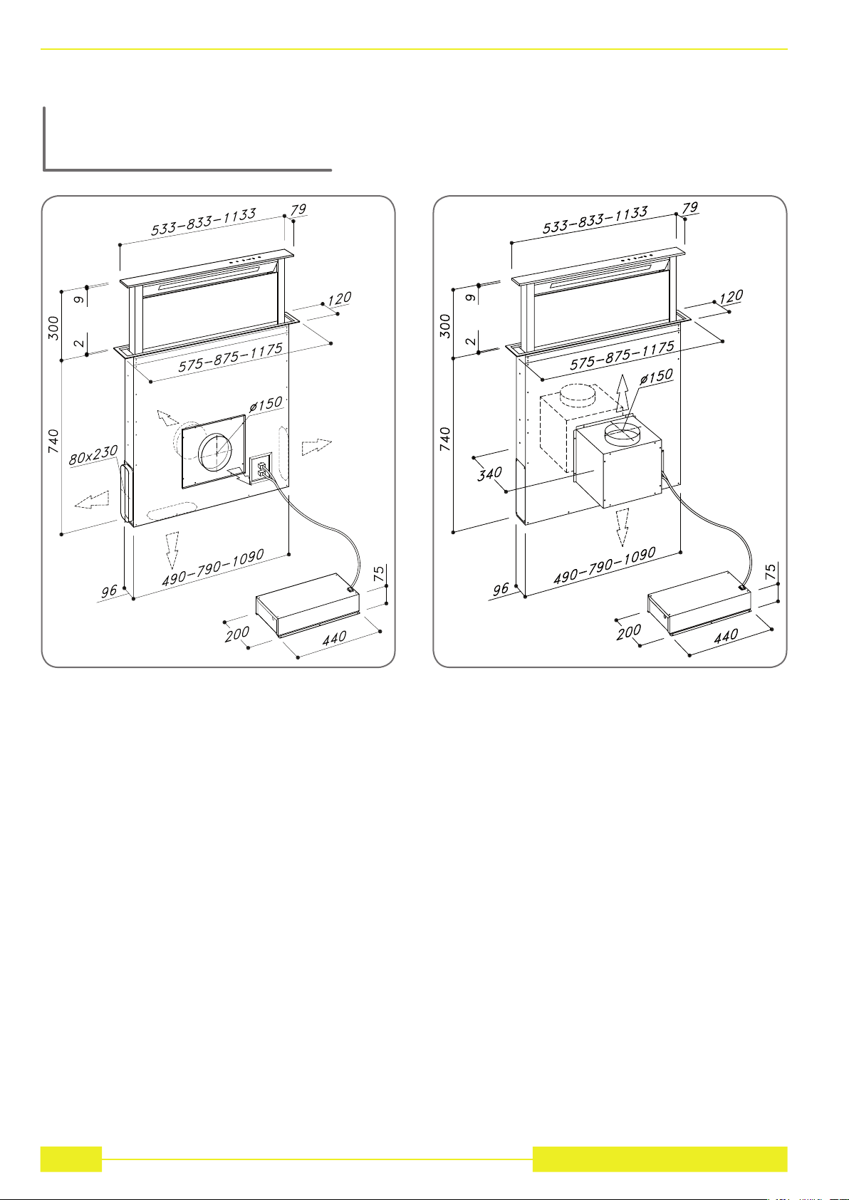
Before the installation of the Downdraft,
please remove the safety piece you can see
in the picture (Fig. 1). Furthermore, please
read carefully all of the following installation
instructions.
• Useanairexhaustingpipewhosemaxi-
mum length does not exceed 5 meters.
• Limitthenumberofelbowsinthepiping,
since each elbow reduces the air capac-
ity of 1 linear meter. (Ex. : if you use no. 2
x 90 ° elbows, the length of piping should
not exceed 3 meters).
• Avoidabruptdirectionchanges.,
• Use a 150 mm. constant diameter pipe
for the whole length.
• Use piping approved by standards in
force.
The manufacturer shall not be deemed re-
sponsible for air capacity or noise problems
caused by failure to comply with the above
instructions and no warranty on the product
shall be provided.
2. Before making the hole, check that there are
no structural or other parts inside the cabi-
net, where the appliance is to be placed,
which could hinder a proper installation.
Check that the dimensions of the Downdraft
and the ones of the cook top are compatible
with the cabinet so that the installation can
be carried out properly.
3. Make a rectangular opening, 842 x 100 mm
in size, in the back of the cook top for the 90
cm model and 542 x 100 mm for the 60 cm
model and 1142 x100 mm for the 120 cm
model. In the version with the motor already
installed, remove the screws and the suc-
tioning unit in order to insert the down-draft
in the hole made.
4. Put the Downdraft in the opening, inserting it
from above as shown in (Fig. 2).
5. Fix the downdraft inside the cabinet, using
the special fixing brackets supplied with the
product (Fig. 3).
Insert the brackets in the lower side of the
downdraft (Fig. 3), in such a way that there
is a 2 mm distance between the lower side
of bracket and the bottom of the cabinet
(Fig. 3).
This distance will allow the traction to be po-
sitioned downwards of the product, at the
moment of fixing, in order to have the stain-
less steel trim perfectly adhering with the
work surface. Before inserting the screws,
please make sure that the appliance is per-
fectly perpendicular with the work surface.
6. Once the installation is complete and after
connecting the appliance to the mains pow-
er, lift up the downdraft and remove the door
block (Fig. 4); then open the door (Fig. 5)
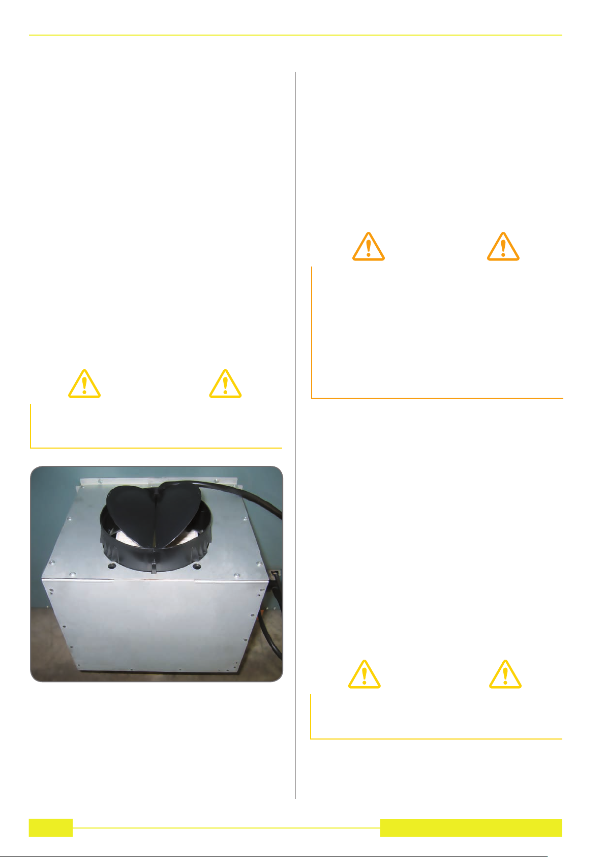
and fit the filters in place (Fig. 6). In the ver-
sion of the Downdraft equipped with internal
motor, install the power unit orienting the air
outlet to the desired position, either down-
wards or upwards (Fig. 7).
The motor can be installed either on the front
or rear side of the downdraft After having in-
stalled the motor, connect the air ducts.
7. For versions with external motor, place the
suctioning unit (external motor) in a suitable
area and fit the exhaust air flue as illustrated.
Then fit the air outlet ducts between the ex-
ternal motor and the downdraft. Select an air
outlet from the five possibilities (Fig. 9) and
fit the union supplied with the appliance.
8. Place the metal box with the electronic com-
ponents in an easily reachable area for even-
tual technical assistance operations. (Fig.
9), connecting the three connectors (9 pole
connector for the actuator control and the
safety control, 4 pole connector for neon
lamp turn on and push-button connector)
(Fig. 10).

DD910BK - DD910SS8
WARNING
Before connecting the air exhaust hose,
make sure that the non-return valves can
rotate freely.
CAUTION
Installation must comply with the regula-
tions in force regarding the ventilation of
enclosed environments. In particular, dis-
charged air must not be conveyed into a
duct used for fumes discharge or discharge
from appliances using gas
or other combustible materials. The use of
discontinued ducts is not allowed without
the approval of a qualified technician.
WARNING
After having replaced the filters, reinstall the
front stainless steel pan’el, otherwise the
Downdraft is not enabled to function.
9. For external motors, connect the motor unit
cable to the relevant connector on the elec-
trical components box.
10. Power the cookerhood.
HOW TO USE THE COOKER HOOD
This appliance is intended to suck cooking
fumes, greases and steam. It has been designed
to work in both suctioning mode, with outside
evacuation, and filtering mode.
Outside - discharge version
The cooker hood can be mounted in the version
with outside discharge of suctioned air: in this
case it is necessary to connect the exhausting
channel to the outside (exhausting pipes are not
supplied with the products.)
Non-return valve blockage
In case of outside air discharge installation, fit a
non-return valve to prevent wind and back air
from entering.
Filtering mode
In case fumes and vapour cannot be evacuated
outside, the appliance can be used in the filtering
mode.
Activated charcoal filters are required for this
type of cooker hood.
Air recycled through the charcoal filters is recir-
culated into the kitchen, thanks to a duct con-
veying the air on one side of the cabinet (Fig.
11).
GREASE FILTER REMOVAL,
MOUNTING THE ACTIVATED CHAR-
COAL FILTER
The removal and fitting of the grease and carbon
filters need to be carried out with the downdraft in
the open position. To open the downdraft, push
the key. Then remove the front panel, push-
ing the upper part of each side at the same time.
The panel will rotate forwards to make it possible
to access the grease filters (Fig. 6). Remove the
grease filters to access the carbon filters (Fig.
12). The replacement of the charcoal filters has
to be carried out accordingly to the effective use
of the Downdraft, and in any case at least once
every 6 months.

DD910BK - DD910SS 9
ELECTRICAL CONNECTION
OF THE COOKER HOOD
If the appliance has no plug or if the plug is not
easily accessible, then a device needs to be fit-
ted to cut it off from the electric network; this
device must have an opening distance between
contacts on all poles of at least 3 mm.
ELECTRICAL CONNECTION
While installing the appliance and carrying main-
tenance operation, make sure it is disconnected
from the electrical network or the fuses are cut
out or removed.
Check that:
• Powerisenough.
• Feeder lines (mains) are in good condi-
tions.
• Thecablesdiametercomplieswithinstal-
lation regulations.
WARNING
Place the metal box containing the elec-
tronic components at a distance of no less
than 65 cm from gas-operated cook tops or
in any case, 65 cm from the suctioning sur-
face of the cookerhood.
NOTE
We recommend installing the metal box
containing the electronic components at
least 10 cm above floor level and at a suita-
ble distance from all heat sources (e.g. oven
sides or cook top).
CAUTION
This appliance is fitted with an H05 VVF 3
conductor, 0.75 mm2 (neutral, phase, and
ground) power cord.
This can be connected up to a 220 - 240 V
mono-phase electrical network through a
CEI 60083 approved power socket, which
must remain accessible after installation, in
compliance with installation regulations.
We decline any responsibility in case of ac-
cidents caused by a lack of ground connec-
tion or incorrect ground connection. The
appliance must be fed through a differen-
tial protection device (RCD), with a nominal
residual current not exceeding 30mA. If the
power cord is damaged, call the after-sales
service to avoid any risk.
WARNING
The downdraft connection to the electrical
network must be carried out only by profes-
sional and qualified technicians.
The downdraft must be connected to a
properly installed and suitable electrical
network.
The electrical system must comply with
VDE0100 standard.
DANGER
If the cooker hood presents any anomaly,
disconnect the appliance or remove the
fuse corresponding to the appliance power
disconnecting line.
NOTE
This appliance complies with the European
Directives 2006/95/EC (Low Voltage Direc-
tive) and 2004/108/EC (Electromagnetic
Compatibility).
This manual suits for next models
1
Other Caple Ventilation Hood manuals
Popular Ventilation Hood manuals by other brands

Eurogrille
Eurogrille COKRHWEUGAS15 user manual

VentAHood
VentAHood Ventilation Hood Models Equipped with K250... installation instructions

Wesco
Wesco WH Scala 200 Use and maintenance instructions

V-ZUG
V-ZUG DI-SM12 operating instructions

V-ZUG
V-ZUG DEHMR 5 operating instructions

V-ZUG
V-ZUG DEHMR 5 operating instructions

System air
System air Villavent SLIM-LINE SL-2A installation, user and maintenance instructions

V-ZUG
V-ZUG DFSG 5 operating instructions

Range Master
Range Master RMDD3004 instructions

Turboair
Turboair TA FL 60 G Instruction on mounting and use

Concept2
Concept2 OPK4760bc manual

ROROS HETTA
ROROS HETTA Vero user manual