CapstanAG EVO User manual

EVO™
Upgrade Kit
Compatible with:
Synchro™
AIM* Command
Installation Instructions
150300-012 Rev. B | Revised 09/2019 | ©2019 Capstan Ag Systems, Inc.
TM

*AIM is a trademark of CNH Industrial LLC, and is not aliated with Capstan Ag Systems, Inc.
All other trademarks are owned by Capstan Ag Systems, Inc. This product may be covered by
one or more U.S. Patents. For more information go to www.BlendedPulse.com
_________________________
©2019 Capstan Ag Systems, Inc. All rights reserved. No part of this publication may be reproduced, stored in a
retrieval system, or transmitted, in any form or by means electronic, mechanical, photocopy,
or otherwise, without prior written permission of Capstan Ag Systems, Inc.

TM
Before System Installation
Chapter 1: Before System Installation
The EVO™Upgrade kit is compatible with existing Synchro™and AIM1Command systems.
Before assembly and installation, read the installation information carefully. Make sure that you
have all of the parts in the kits. Read all of the instructions in this document, the system operator
manual, and the machine manuals. The system operator manual includes information on operation,
adjustments, troubleshooting, and maintenance.
Attention: The correct function of the EVO™system cannot be guaranteed if the current
PWM system is not functioning correctly. Do the following procedures BEFORE installation to
verify the correct function of the existing system.
No warranty or returns of the system will be honored if the existing system is not verified to
function correctly before installation of the EVO™system.
For further assistance contact your CapstanAG representative.
Before installation of a new system, you must make sure that the existing AIM Command system is
operating correctly. Do these procedures:
• Clean the nozzle valves and inspect the plunger seals
• Do a Check of the Conventional Spray System
• Do a Check of the System Flow Control
• Do a Check of the System Pressure Control
Clean the Nozzle Valve(s)
Warning: Chemical residues may be present in the agricultural equipment. Always use the
proper personal equipment to avoid personal injury.
1. Release pressure from the system before servicing.
2. Clean the system before installation or service of the fittings, hoses, valves, or nozzles.
3. Remove the valve body.
4. Remove the plunger.
5. Inspect the O-rings.
6. Wash the nozzle valve components to remove any debris.
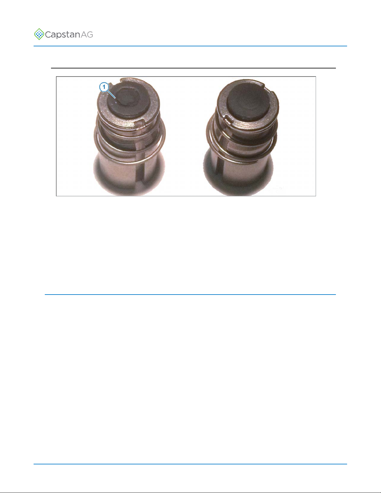
7. Inspect the plunger for wear or damage.
8. If there is wear or damage to the plunger, replace the plunger.
9. Inspect the valve body.
Make sure that the orifice is not plugged with debris, worn, or damaged.
10.If there is wear or damage to the orifice, replace the valve body.
11.Wash the nozzle body components to remove any debris.
Important: Do not use brake cleaner. Brake cleaner can damage the seal.
Important: During installation, apply 40 lbf in of torque to the coil when it threads into the valve
body to properly seat the O-ring.
1AIM is a trademark of CNH Industrial LLC, and is not affiliated with Capstan Ag Systems, Inc.
©2019 Capstan Ag Systems, Inc. 3EVO Upgrade Kit

TM
Before System Installation
Plunger Seal Inspection
Fig. 1:
After extended use, the plunger seal will wear a groove (1) where the seal impacts the hard orifice
seat. Replace plunger if worn or damaged.
As the groove deepens the pressure capacity of the valve will decrease until the pressure capacity
interferes with the operating pressure of the system.
The result is erratic pulsing, often described as “flickering.” The system will operate normally at lower
pressures until replacement parts can be installed. High operating pressures and abrasive chemicals
will accelerate the wear of the plunger seal material.
Do a Check of the Conventional Spray System
Before installation of the EVO™Upgrade Kit, make sure that the existing system operates in the
conventional spray mode correctly.
1. Open the intermediate bodies (through bodies) on the spray booms and move existing tips to
those bodies if no other tips are installed.
2. Move the Auto/Off/Manual switch to the O position.
3. Turn on the key switch for the machine.
4. Power on the rate controller.
5. On the rate controller, change the control valve type to PWM or PWM/AIM Command PRO.
6. On the rate controller, set a test speed.
7. On the rate controller, enter a target rate.
8. Turn on the master switch and the boom switches.
If the system sprays and maintains the target rate, continue to the installation.
If the system does not operate correctly, find and correct the problem(s) before continuing with the
EVO™upgrade installation.
©2019 Capstan Ag Systems, Inc. 4EVO Upgrade Kit

TM
Before System Installation
Do a Check of the Existing System Flow Control
1. Make sure that the intermediate valve bodies are closed and nozzles are placed on the bodies
with blended pulse solenoids in place.
2. Turn on the key switch for the machine.
3. Power on the rate controller.
4. Change the control valve type to:
• AIM Command
• Inline servo
5. Set a test speed in rate controller.
6. Disable any automatic section control feature in the rate controller.
7. Set the rate controller to manual rate mode.
8. Move the Auto/Off/Manual switch to A position.
9. Turn on the boom section switches and master switch.
10.Press the manual rate increase button on the rate controller to a maximum flow.
You should see no pulsing of the system.
11.Press the manual rate decrease button on the rate controller to a minim flow.
You should see a very distinct pulsing of the system.
If these steps are completed successfully continue to the next procedure: Do a Check of the Existing
System Pressure Control.
Do a Check of the Existing System Pressure Control
1. Turn on the key switch for the machine.
2. Move the Auto/Off/Manual switch to the O position and start the machine.
3. Idle the machine and move the Auto/Off/Manual switch to the A position.
4. Move the throttle to half-open.
The pressure should move to the pressure setpoint and hold that pressure.
5. Move the pressure control switch to the + position.
The pressure should increase.
6. Move the pressure control switch to the – position.
The pressure should drop.
7. Use the pressure control switch to set the pressure near 50 psi.
8. If the pressure will not reach 50 psi, bump the throttle up.
9. Move the P1/P2 switch to the other position.
The pressure should move to the second set point pressure.
10.Use the pressure control switch to set the second pressure at 20 psi.
11.Toggle between the P1 and P2 positions.
The system pressure should move back and forth between 20 and 50 psi. The transition should
take a second or so, and the pressure may go past but should come right back to the target
pressure.
12.If the pressure seems unstable, a PWM cartridge test should be performed.
Contact CapstanAG for the tuning procedure.
©2019 Capstan Ag Systems, Inc. 5EVO Upgrade Kit

TM
Before System Installation
©2019 Capstan Ag Systems, Inc. 6EVO Upgrade Kit

TM
Kit Parts List
Chapter 2: Kit Parts List
Part
Number Description Parts Description Qty
116200-014 3-pin Extension Harness-4 ft Extension 3-Conductor x 4ft, 14 ga 4
116200-045 2-Pin Tower Dust Plug HN DUST PLUG 2 PIN TOWER WP 4
116200-046 3-Pin Tower Dust Plug HN DUST PLUG 3 PIN TOWER WP 2
116200-048 3-Pin Shroud Dust Plug HN DUST CAP 3 PIN SHROUD WP 7
116200-051 2-Pin Shroud Dust Plug Dust Plug, 2 Pin WP Shroud 2
116200-078 4-Pin Tower Dust Plug HN DUST PLUG 4 PIN TOWER WP 4
120140-016 DB9 Serial Cable CABLE SERIAL DB9 MTOF 15' 1
120140-028 8-32 Male/Female Hex Standoff HEX STANDOFF, M/F 8-32 SS 4
150003-005 CAN Terminator CAN TERMINATOR 2
150006-010 Cab Box Display Cab Box Display Assy EVO 1
150150-010 Pressure Transmitter Module Assembly, Pressure Transmitter, EVO 1
150200-010 Boom Transmitter Module Assembly, Boom Transmitter A, EVO 1
709031-505 8-32 x 5/16 Screw SCREW #8-32 X 5/16" SSPAN SS 4
713501-508 Split Lock Washer WASHER #8 SPLIT LOCK, SS 4
715040-178 Cable Ties TIE CABLE 12" BLACK 68
150005-008 PSI Adapter Harness HARNESS, ADAPTER PSI EVO-
ACUPGRADE 1
150300-001 Mounting Plate Module Mount Plate, EVO AC Retro 1
150100-010 Smart Driver Module Assembly, Controller, Smart Driver, EVO 7
150003-006 Power to CAN X Harness Power to Can X for AC Retro 1
150005-005 EVO Shutoff Harness-4 ft Harness, Extension Shutoff, 4ft, EVO, for
AC Retro 1
150004-040 CAN-Bus Extension Harness-40 ft HARNESS, EXT, CAN-BUS, 40FTPLUG
TO PLUG 1
150003-004 Display Harness with GPS Drop Harness, Display w/GPS Drop 1
116200-077 4-Pin Tower Square Dust Plug HN DUST PLUG 4 PIN TOWER SQWP 1
118603-111 RAM Mount RAM MOUNT 2 7/16"RNDBASE
1"UBoltbasew/1.5"Ball 1
620303-023 Plug-to-Plug Adapter Harness HARN, ADAPTER, PLG-PLG 6" 5
150005-010 Servo Adapter Harness Harness, Adapter, Servo, for AC 1
150250-050 Servo Transmitter Module Assembly, Controller Servo, EVO 1
©2019 Capstan Ag Systems, Inc. 7EVO Upgrade Kit

TM
Kit Parts List
Part
Number Description Parts Description Qty
705725-141 20 A Fuse FUSE 20 AMP TYPE ATO/ATC YL 3
705725-150 20 A Mini Fuse Fuse, 20 Amp, Mini ATC 3
706530-356 12-pin D Dust Plug HN DUST PLUG 12- PIN DEUTSCh DT A
Key 1
Machine
Specific GPS Adapter Cable See Technical Bulletin TB19-04 for more
information about which cable is needed
for your system.
1
©2019 Capstan Ag Systems, Inc. 8EVO Upgrade Kit

TM
Kit Parts List
System Layout
Seven-section Schematic
Fig. 2:
Callout Description Callout Description
(1) Mounting Plate (6) PSI Adapter Harness
(2) Plug-to-Plug Adapter Harness-6 in (7) EVO Shutoff Harness-4 ft
(3) CAN Terminator (8) Cab Box Display
(4) Power to CAN X Harness (9) Display Harness with GPS Drop
(5) Servo Adapter Harness (10) CAN-Bus Extension Harness-40 ft
©2019 Capstan Ag Systems, Inc. 9EVO Upgrade Kit

TM
Kit Parts List
Six-section Schematic
Fig. 3:
Callout Description Callout Description
(1) Mounting Plate (6) PSI Adapter Harness
(2) Plug-to-Plug Adapter Harness-6 in (7) EVO Shutoff Harness-4 ft
(3) CAN Terminator (8) Cab Box Display
(4) Power to CAN X Harness (9) Display Harness with GPS Drop
(5) Servo Adapter Harness (10) CAN-Bus Extension Harness-40 ft
©2019 Capstan Ag Systems, Inc. 10 EVO Upgrade Kit

TM
Kit Parts List
Five-section Schematic
Fig. 4:
Callout Description Callout Description
(1) Mounting Plate (6) PSI Adapter Harness
(2) Plug-to-Plug Adapter Harness-6 in (7) EVO Shutoff Harness-4 ft
(3) CAN Terminator (8) Cab Box Display
(4) Power to CAN X Harness (9) Display Harness with GPS Drop
(5) Servo Adapter Harness (10) CAN-Bus Extension Harness-40 ft
©2019 Capstan Ag Systems, Inc. 11 EVO Upgrade Kit

TM
Kit Parts List
©2019 Capstan Ag Systems, Inc. 12 EVO Upgrade Kit

TM
Installation—EVO™Upgrade Kit
Chapter 3: Installation—EVO™Upgrade Kit
Fig. 5:
1. Mount the cab display (1) in the cab of the machine with the hardware (2) supplied with the kit.
Make sure that the cab display is within view and reach of the operator.
Fig. 6:
2. Install one end of the display harness (1) into the connector at the back of the cab display (2).
3. Route the display harness to the back of the cab of the machine.
4. Connect the GPS connector (3) to the machine-specific GPS Y-cable.
5. Connect the other end of the GPS Y-cable to the existing GPS source.
6. At the back of the cab, connect the display harness to the CAN Bus extension harness—40ft (4).
7. Route the CAN Bus extension harness—40ft to the back of the machine.
©2019 Capstan Ag Systems, Inc. 13 EVO Upgrade Kit

TM
Installation—EVO™Upgrade Kit
Fig. 7:
8. Remove the module cover from the back from the sprayer.
9. Remove the master (1) and slave flow meter modules (2) from the existing mounting plate(s).
Do not disconnect the harness connectors at this time.
©2019 Capstan Ag Systems, Inc. 14 EVO Upgrade Kit

TM
Installation—EVO™Upgrade Kit
Fig. 8:
10.Install the standoffs (1) to the existing mounting plate.
©2019 Capstan Ag Systems, Inc. 15 EVO Upgrade Kit

TM
Installation—EVO™Upgrade Kit
Fig. 9:
11.Install the module mounting plate (1) to the standoffs with the screws (2) and lock washers.
Make sure that all of the screws can be installed before tightening the screws all the way.
Fig. 10:
12.Connect the Display, Left Trunk connector (1) of the power to CAN X harness to the end of the
CAN Bus extension harness—40ft (2).
13.Route the shutoff adapter harness (3) connected to the boom signal transmitter module to the
back of the mounting plate.
©2019 Capstan Ag Systems, Inc. 16 EVO Upgrade Kit

TM
Installation—EVO™Upgrade Kit
Fig. 11:
14.Disconnect the existing boom shutoff connectors (1).
The existing boom shutoff connectors may be located behind the mounting plate and to the left of
the center rack of the machine.
To verify the correct connectors follow the harness from the AIM Command modules along the
existing AIM Command harnessing.
15.Connect the shutoff adapter harness connector (2) to the existing boom shutoff connector.
16.Install a dust plug to the other existing connector.
©2019 Capstan Ag Systems, Inc. 17 EVO Upgrade Kit

TM
Installation—EVO™Upgrade Kit
Fig. 12:
17.Disconnect the connector (1) labeled SERVO from the master flow module.
18.Connect the servo adapter harness (2) connected to the servo transmitter module to the master
servo connector.
©2019 Capstan Ag Systems, Inc. 18 EVO Upgrade Kit

TM
Installation—EVO™Upgrade Kit
Fig. 13:
19.Disconnect the connector (1) labeled SENSOR from the pressure module (2).
20.Connect the pressure adapter harness (3) from the pressure transmitter module between the PSI
connector and the pressure module as shown.
©2019 Capstan Ag Systems, Inc. 19 EVO Upgrade Kit

TM
Installation—EVO™Upgrade Kit
Fig. 14:
The smart drivers have been assembled in serial number order from smallest to largest. The lowest
serial number smart driver will drive the leftmost section of the system.
(1) Smart Driver #1—Section 1
(2) Smart Driver #2—Section 2
(3) Smart Driver #3—Section 3
(4) Smart Driver #4—Section 4
(5) Smart Driver #5—Section 5
(6) Smart Driver #6—Section 6
(7) Smart Driver #7—Section 7
©2019 Capstan Ag Systems, Inc. 20 EVO Upgrade Kit
Other manuals for EVO
2
Table of contents
Other CapstanAG Farm Equipment manuals
Popular Farm Equipment manuals by other brands

RITEWAY
RITEWAY F Series Operator's manual & parts list

Producer's PRIDE
Producer's PRIDE Ranch Chicken Coop Care Instructions

Fritzmeier
Fritzmeier Isaria PRO Active Operating and maintenance manual

Frontier
Frontier DH3499 operating manual

Mandam
Mandam Hybro 3,0 instruction manual

Case IH
Case IH FARMLIFT 525 Service manual

Landoll
Landoll Icon 1205 Carry All Service and parts manual

Yetter
Yetter MAVERICK HR PLUS 2984 Series Operator's & parts manual

Prevue Hendryx
Prevue Hendryx ECONO-1614 Assembly

Mandam
Mandam MBS instruction manual

Goldacres
Goldacres Traymount T3 Operator's & parts manual

Kerbl
Kerbl 82806 instruction manual