Carbatec CTJ-196 User manual

AUTHORISED SERVICE AGENTS:
CARBA-TEC Pty. Ltd.
40 Harries Road
Coorparoo, QLD 4151
Ph: (07) 3397 2577
Fax: (07) 3397 2785
CARBA-TEC (NSW) Pty. Ltd.
32 Percy Street
Auburn, NSW 2144
Ph: (02) 9649 5077
Fax: (02) 9649 7044
CARBA-TEC (MELB) Pty. Ltd.
80 - 82 Osborne Avenue
Springvale, VIC 3171
Ph: (03) 9558 4200
Fax: (03) 9558 5133
CARBA-TEC (WA)
151 Balcatta Road
Balcatta, WA 6021
Ph: (08) 9345 4522
Fax: (08) 9240 1014
CARBA-TEC NZ Ltd.
110 Harris Road
East Tamaki, Auckland
Ph: (09) 274 9454
Fax: (09) 274 9455

®
6” JOINTER
MODEL CTJ-196
INSTRUCTION MANUAL

2
SAFETY WARNING:
This list of do’s and do nots is not exhaustive and is not a substitute for common sense and best
practices.
Woodworking machines are potentially dangerous, it is important to observe all safety instructions
while operating this machine.
• Always wear eye and ear protection.
• Always unplug the machine from the power source before making any adjustments.
• Always use a licensed electrician for any installation or electrical repair work.
• Do not wear loose clothing, jewellery or other loose ornamentation.
• Long hair should be protected by netting or other means to prevent ingress into the machines
working parts.
• Keep all safety guards in place and well maintained.
• Ensure all adjusting keys, spanners and tools are removed before machine is switched on.
• Keep children and unauthorised persons away from machine even when not in use.
• Do not use machine for any other purpose than that for which it was designed.
• Do not use excessive force, or exceed capacity of machine by attempting to take too large a cut.
• At no time should machine be unattended whilst in operation.
• When machining timber of any size, use push blocks to avoid placing hands too close to
turning cutterhead.
• Do not put hands inside machine whilst it is running.
• Wood dust is a health hazard, ensure correct dust extraction is fitted.
• Cutter blades should be kept sharp at all times. Blunt blades are a major cause of accidents
and machine failure. Damage to the machine caused by blunt blades is not covered by warranty.
• This machine should be used in an area with good lighting and ventilation.
• Keep the floor and adjacent areas around the machine dry and clean.
• Do not lean or climb on the machine as it may tip.
• Always maintain a balanced stance when operating this machine.
• Do not operate this machine whilst on medication or under the influence of alcohol or drugs.
SAFETY RULES FOR JOINTERS
1. Keep cutterhead blades sharp and clean of resin buildup.
2. Check that guard swings free of cutterhead and is always in place when jointer is in use.
3. Check infeed and outfeed table are locked in place before using machine.
4. Always use the fence when planing, do not attempt to freehand workpiece without supporting it against
the fence.
5. Use a push block to protect hands, especially when machining very thin boards where your hands are
close to the cutterhead.
6. If your material is wider than 35mm do not take a cut larger than 3mm.Maximum cut for wide material
should be 1.5.
7. Make sure jointer is turned off and unplugged before performing any maintenance work, such as
blade changing.
UNPACKING
Your jointer comes in two packing cartons, the assembled jointer and fence components in one and the
assembled base in the other.The packing grease is easily removed with mineral turpentine.
The jointer stand contains the motor and switch already wired and mounted. Do not connect the motor to
power source until the jointer is completely assembled.
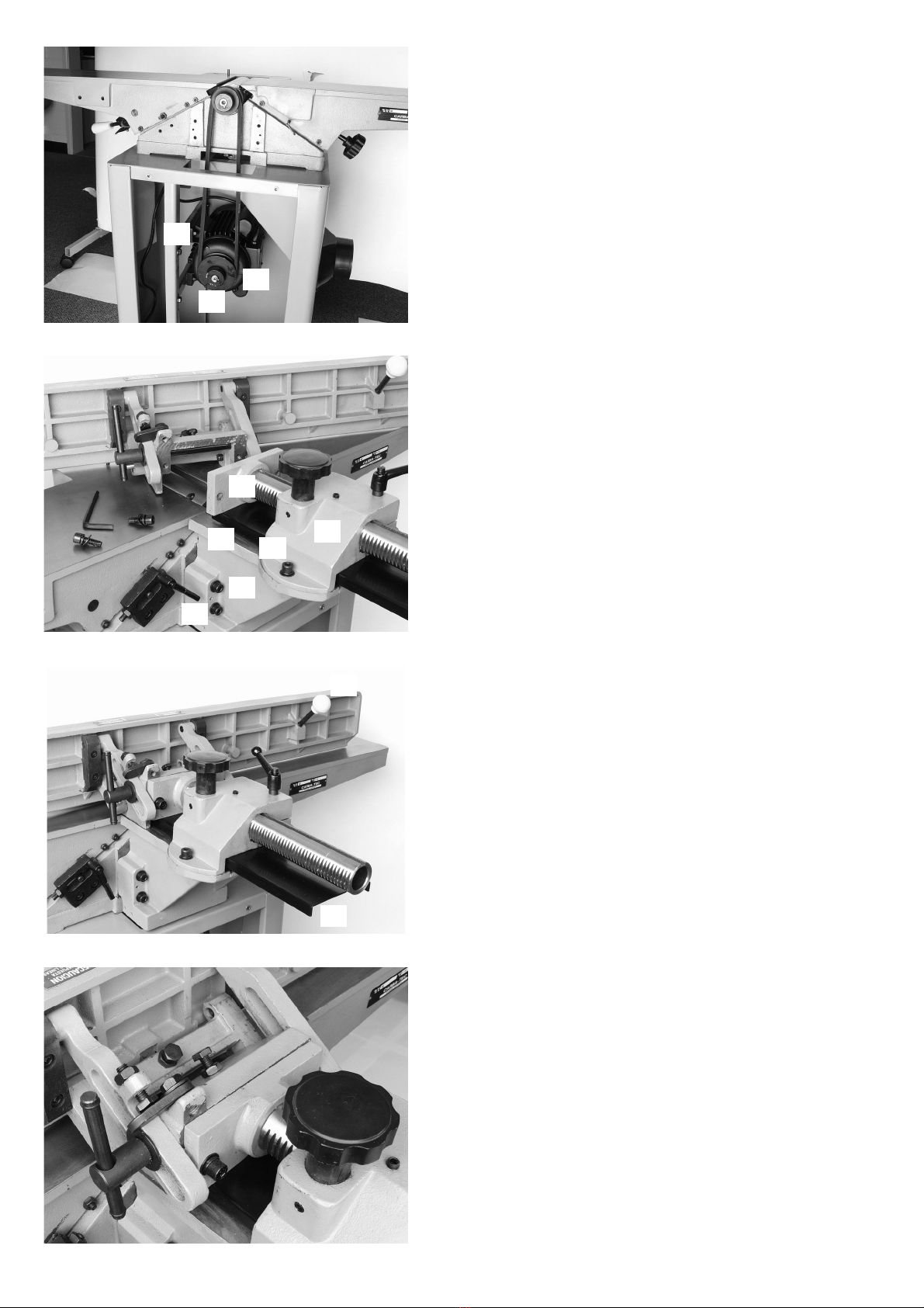
ASSEMBLING JOINTER TO STAND
1. Take off side panel by removing the three screws at the top of the panel and loosening the two screws at the base
of the panel, it should now just lift up and off.
2. Line up the 3 holes on top of the stand with the 3 threaded holes that are located on the bottom of the jointer,
using the 8mm allen key provided fix the 1" hex head screws and washers into place. Note the outfeed end
of the jointer should be facing the dust chute outlet on the base.

3
Fig. 2
Fig. 1
Fig. 3
Fig. 4
MOTOR PULLEY ASSEMBLY
Fix the motor pulley Fig. 1 (A) onto the motor shaft mak-
ing sure the hub of the pulley is facing out. Insert key
into the keyway of the pulley and motor shaft. Make
sure you tighten the set screw Fig. 1 (C) with the allen
wrench supplied.
ALIGNING BELT PULLEYS
Place the belt around the pulleys on the motor and the
cutterhead. Using a straight edge on the face of both
pulleys make sure they are in line. If adjustment is
needed, the motor pulley can be moved foreward or
back on the motor shaft. An altenative is to loosen the
screws on the motor mounting plate Fig. 1 (B) and shift
the motor forward or back, be sure to tighten them
again afterwards.
CHECKING BELT TENSION
If the belt tension is correct, there should be 1" deflec-
tion at the centre span of the belt. If adjustment is
needed,the motor may be raised or lowered by loosen-
ing the motor mounting screws and pushing the motor
up or down to adjust tension. Don't forget to retighten
the screws after positioning is complete. Recheck pulley
alignment to ensure it has not been disturbed. Once you
are satisfied with the belt pulley arrangement, replace
the side panel.
PULLEY GUARD AND CARRIAGE MOUNTING
BRACKET
It is essential for the safe use of the machine that the
pulley guard Fig. 2 (A) is in place before operating the
jointer. Position the two alignment pins in the pulley
guard, with the two holes in the side of the jointer,
attach guard using the 4 x 55mm long hex head screws
Fig. 2 (E). Attach carriage assembly Fig. 2 (B) to carriage
mounting bracket Fig. 2 (D) using the 2 of 8 x 20mm
long hex socket screws supplied Fig. 2 (C).
FENCE ASSEMBLY
The fence is fitted to the carriage assembly via the two
holes in the front plate Fig 2. (F). The short fence han-
dle Fig. 3 (A) is fitted to the to the infeed side of the
fence, and the longer handle to the outfeed side (not
shown).
COMPLETED FENCE ASSEMBLY FIG. 4
A
C
A
F
A
E
DC
B
B
B

4Fig. 8
Fig. 5
Fig. 6
Fig. 7
FENCE
The fence is totally adjustable, and can move right
across the table or tilt to 45 degrees.
To move fence loosen the locking handle Fig. 7 (A) and
turn the knob Fig. 7 (B) until fence is at desired loca-
tion, tighten locking handle.
For your safety, as the fence is moved across, the rear
cutting guard moves over the blades at the back to
cover them Fig 3 (B), previous page.
To tilt fence in or out, loosen locking handle, Fig. 7 (A)
hold the fence tilting handle, rotate 90 degree flip stop,
Fig. 7 (C) and tilt fence to the required angle. Tighten
locking handle Fig. 7(A).
The fence is fitted with positive stops that will enable
you to quickly change the angle of the fence from 90 to
45 degrees, both in the inward and outward positions.
To set fence to 90 degrees. Make sure that the adjust-
ment screw is in contact with the flip stop Fig. 7 (C).
Check with a square to make sure of accuracy. If you
need to make an adjustment, loosen lock handle, Fig. 7
(A) and lock nut, Fig. 7 (D) turn adjustment screw Fig. 7
(E) until fence is in correct position. Tighten lock nut Fig.
7 (D) and handle Fig. 7 (A).
To set positive stop to 45 degrees with fence facing out,
loosen lock handle Fig 7 (A), rotate flip stop Fig. 7 (C),
tilt fence out to 45 degrees, and tighten lock handle.
Check with a square. When you have the correct angle.
Turn adjustment screw Fig. 7 (F) so as it touches the
top edge of the fence. This becomes your stop for 45
degrees with the fence facing out.
To set positive stop with fence facing in at 45 degrees
Loosen lock handle Fig. 7 (A), rotate flip stop and rotate
fence in. Once it is in position turn adustment screw Fig.
7 (G) so it touches fence. This becomes your positive
stop. Tighten locking handle.
POSITIVE STOP FOR INFEED TABLE
A
A
G
F
D
E
B
C

5
Fig. 9
Fig. 11
TABLE ADJUSTMENTS.
INFEED TABLE
The infeed table adjustment determines the depth of
cut, by raising or lowering the table in relation to the cut-
terhead.
The lower the infeed table the larger the cut. Loosen the
table lock handle Fig. 8 (A) at the back of the machine
and raise the table by releasing the lever Fig. 9 (A) and
pushing the handle up or down Fig. 9 (B), the gauge in
the front Fig. 10 (A) will tell you exactly what your depth
of cut is.
It is possible to preset the positive stops to maximum
and minimum depth of cut so it is not necessary to con-
sult the gauge each time you wish to change to these
settings Fig 8.
OUTFEED TABLE
The outfeed table should be level with the jointer knives
at the highest point of their rotation. Once set to this
height it should not be altered,the depth of cut adjust-
ment comes from the infeed table only. If it is necessary
to adjust the outfeed table, loosen the locking screw at
the back of the jointer, Fig. 13 (C) and turn the knob Fig.
11 (A) under the outfeed table, this will raise or lower
the table. Don't forget to tighten the locking screw Fig.
13 (C).
ADJUSTING TABLE GIBS
The gibs Fig. 12 (A) are designed to take up any play
that may exist in the sliding dovetail that joins the in
and outfeed table casting to the base casting. If there is
any adjustment needed;
1. There are three lock nuts Fig. 13 (A) for the infeed
table and two for the outfeed table Fig. 13 (B). These
must be loosened.
2. For the infeed table, loosen the table locking lever
Fig. 8 (Previous Page), and turn the gib adjustment
screws Fig 12 (B), start with the lower adjustment
screw and work your way to the top. Slightly raise the
back edge of the table as you make the adjustment
to prevent any sagging.
3. Once the gib has been adjusted to a secure fit
tighten the lock nuts and the table locking lever.
4. Repeat the process for the outfeed table, note that
this table has a table locking screw, Fig. 13 (C). It is
essential that these screws are tight if the tables
move up and down too freely, it will be difficult to
attain an accurate result.
Fig. 10
Fig. 12 Fig. 13
A
A
A
A
A
A
B
B
C
B
C
B

6
Fig. 14
Fig. 15
Fig. 16
Fig. 17
KNIFE SETTING
The 3 blades in your jointer are factory set, and there-
fore should already be set to the right height and parral-
lel to the cutterhead. If for some reason you need to
adjust the blades
These are the steps to follow.
1. Disconnect machine from power source.
2. Lower infeed table.
3. Remove cutterhead guard.
4. Lay a steel straight edge along the outfeed table so
it extends across the cutterhead Fig. 15. When the
cutterhead is turned by hand, the blades should
just touch the bottom of the straight edge.
5. If the knives are high or low at the ends, loosen the
four (4) screws that hold the knife locking bars in
place Fig. 14 (A), and turn the knife raising screws
Fig. 15 (A), clockwise to raise the knives, and anti
clockwise to lower them. When lowering the knives
you may need to push them down gently onto the
raising screws with a piece of wood after screws
are turned.
6. Tighten locking bar screws. Fig. 14 (A)
7. Repeat for all three knives. It is important that they
are the same height.
8. Replace cutterhead guard.
REPLACING KNIVES
When it is time to fit new knives to your jointer,follow
these steps.
1. Disconnect machine from power source and unplug.
2. Slide the fence to the back so it is clear of the
knives.
3. Beware of exposed knives.
4. Remove cutterhead guard.
5. Loosen the 4 knife locking bar screws Fig. 14 (A),
remove knife and locking bars. Fig. 16.
6. Repeat for other knives.
7. Remove any resin that may have built up, either on
locking bars or in slots.
8. Lower the knife adjustment screws, by turning them
anti-clockwise. Fig. 17 (A).
9. Replace knife locking bars and knives. Make
certain the knives are sitting down as far as
possible on the adjustment blocks.Tighten the knife
locking bar screws enough to stop them from
moving freely, but not so tight as to stop them from
being adjusted by the movement of the knife
adjustment blocks.
10. You now need to set each knife according to the
procedures described in numbers 4 to 8 in the
knife setting section.
WWAARRNNIINNGG..MMAAKKEESSUURREEAALLLLLLOOCCKKIINNGGSSCCRREEWWAARREE
TTIIGGHHTTEENNEEDDSSEECCUURREELLYYBBEEFFOORREETTUURRNNIINNGGMMAACCHHIINNEE
OONN!!!!
A
A
A
A
A
A
B
B

7
CUTTERHEAD GUARD
It it essential that the jointer is not operated without the
cutterhead guard.
1. Insert post Fig. 19 (A) through the hole in the infeed
table making sure that the spring assembly in the
knob Fig. 19 (C) engages into the slot at the bottom
of the post Fig. 19 (A). You will need to turn the
knob to provide tension in the spring before
inserting post. It is this tension that makes the
guard spring back over the cutterhead.
2. If the tension is too great or too small, adjust by
removing the guard and rotating knob. Fig. 19 (C).
TURNING THE MACHINE ON & OFF
This machine is fitted with a switch that needs to be
pulled out to switch the machine on and pushed in to
switch the machine off. You can also lock the switch in
the off position Fig. 22, by removing the yellow key Fig.
21 (A).
Fig. 18
Fig. 19
Fig. 22
Fig. 20
Fig. 21
Locked
Position
On
Position
Off
Position
A
A
C
B

8
Fig. 23
Fig. 24
Fig. 25
RABBETING FACILITY
This jointer is able to perform a rabbetting operation, to
do this the cutterhead guard must be removed.
Remember to replace the cutterhead guard before per-
forming any other operation.
1. Adjust fence to width of rabbet.
2. Lower the infeed table to the depth of rabbet. If
rabbet is quite deep it may be necessary to make 2
or more passes at increasing depths to attain full
depth of cut.
NOTE: BE SURE TO USE PUSH BLOCKS WHEN
RABBETTING.
PLANING OR SURFACING FACE
Surface the widest face first to establish one, totally
straight face. This then becomes the reference which
goes against the fence allowing squaring of the edge of
the board.
Always use a push block when planing or surfacing.
JOINTING EDGES
The most common operation on a jointer. Makes edge
square to planed face and creates a straight surface for
edge joining of boards.

9

10

11

12

13

14
ALL ELECTRICAL WORK SHOULD BE UNDERTAKEN BY A
LICENSED ELECTRICAL CONTRACTOR.

15
NOTES
Table of contents
Other Carbatec Power Tools manuals
Popular Power Tools manuals by other brands

Bosch
Bosch GSH 27 VC Professional Original instructions

Greenlee
Greenlee GREENLEE KWIK-STRIPPER 45019 instructions

Makita
Makita KP0810 instruction manual

BE Ag & Industrial
BE Ag & Industrial BE-QH1GI Operations & parts manual

Chicago Electric
Chicago Electric 66001 Set up and operating instructions

HPC
HPC Blitz 1200CMB manual

Wickes
Wickes PHG200B quick start guide

STEINEL
STEINEL HG 2320 E Translation of the original operating instructions

Central Pneumatic
Central Pneumatic CENTRAL PNEUMATIC 68128 Set up and operating instructions

Go-On
Go-On AS 18-2 operating instructions

iTOOLco
iTOOLco WCT1000 user guide

Far Tools
Far Tools P 13F Original manual translation