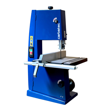
Carbatec SBW-6300 User manual

XM000557 BELAUC

p.
2
GENERAL SPECIFICATIONS
1. General Specification
2. Writing Diagrams
3. Warnings
3.1 Safety rules for all tools
3.2 Safety instructions
3.3 Warning labels & workstation
3.4 Safety working practice
4. Supplies and consumption
5. Front side of band saw
6. Rear side of band saw
7. Operation instruction
8. Part list
9. Maintenance & trouble shooting
p.3
p.3
p.4
p.5
p.6
p.7
p.7 ~ p.8
p.12
p.13
p.13
p.14 ~ p.15
p.16 ~ p. 31
p.32
GENERAL INFORMATION
The SBW-6300 band saw is a well designed industrial machine that provide variety of wood
working fuctions to meet your higher needs of a Band Saw. Followings are the basic
functions you will find in this machine:
1. Quick Changed Saw Blade System given you an easy way to replace blade to cut
different quality wood materials.
2. Adjustable Rip Fence can assist you to cut desired shapes.
3. Accurate Miter Gauge can let you creat any curves you desire.
4. Effective Ball Bearing Guide System will let the band saw blade run more smoother.
5. Humanized Dust Chutes collect extra wood-chips, and give you a better working
environment.
6. Extended 16" Height Space provides you a bigger working space to cut wider and
higher wood selections.

1.GENERAL SPECIFICATIONS
2.WIRING DIAGRAM
p.3
Machine overall size
Table size
Cast iron wheel size
Table height
Machine net weight
Cutting height (under ball bearing guide)
Cutting width(w/o fence)
Table tilting angle
Blade width
Saw blade speed
Blade guide
Driving belt
Dust chute
Base size
Braking system
Motor
Overload protection switch
Fence
Ctn Qty/20°Ø/40°Ø
1191(L)x745(W)x2060(H) mm
850(L)x600(W)x50(H) mm
630mm
830mm
380kgs
400mm
610mm
0-45_ (R) CE: 0-20_ (R)
6mm-38mm (Standard 25mm L=4600mm)
1630 M/min (820 /min)
6202zz ball bearing
A type x 2 grooves
100mm x2
1050(L)x600(W)x80(H)mm
Electronic braking switch
3.75KW/4p/3~/50Hz
400V/3~/50Hz
Cast iron design ,30(W)x90(H)mm
14sets/30sets
Specification SBW-6300 Band Saw
Item Spec

3.WARNINGS
p.4
For Your Own Safety Read Instruction Manual Before Operating Band Saw
a) Wear eye protection.
b) Do not remove jammed cutoff pieces until blade has stopped.
c) Maintain proper adjustment of blade tension, blade guides, and thrust bearings.
d) Adjust upper guide to just clear workpiece.
e) Hold workpiece firmly against table.
f) The conversion from 230V to 400V operation must be done by a qualified electrician.
g) The blade saw is to be disconnected from the power supply while the motor is being mounted, connected,
or reconnected.
1. Always wear protective eye wear when operating machinery. Eye wear shall be impact resistant,
protective safty glasses with side shields.
2. Wear proper apparel. No loose clothing or jewelry which can get caught in moving parts. Rubber soled
footwear is recommended for best footing.
3. Do not overreach. Failure to maintain proper working position can cause you to fall into the machine or
cause your clothing to get caught-pulling you into the machine.
4. Keep guards in place and in proper working order. Do not operate the machine with guards removed.
5. Avoid dangerous working environments. Do not use stationary machine tools in wet or damp locations.
Keep work areas clean and well-lit. Special electrics should be used when working on flammable materials.
6. Avoid accidental starts by being sure the start switch is "OFF" before plugging in the machine.
7. Never leave the machine running while unattended. Machine shall be shut off whenever it is not in operation.
8. Disconnect electrical power before servicing. Whenever changing accessories or general maintaince is done
on the machine, electrical power to the machine must be disconnected before work is done. Safe by using
padlocks, master switches, or by removing starter keys.
9. Maintain all machine tools with care. Follow all maintenance instructions for lubricating and the changing of
accessories. No attempt shall be made to modify or have makeshift repairs done to the machine. This not
only voids the warranty but also renders the machine unsafe.
10. Machinery must be anchored to the floor.
11. Secure work. Use clamps or a vise to hold work, when practical. It is safer than using your hands and it
frees both hands to operate the machine.
12. Never brush away chips while the machine is in operation.
13. Keep work area clean. Cluttered areas invite accidents.
14. Remove adjusting keys and wrenches before turing machine on.
15. Use the right tool. Don't force a tool or attachment to do a job it was not designed for.
16. Use only recommended accessories and follow manufacturers instructions pertaining to them.
17. Keep hands in sight and clear of all moving parts and cutting surfaces.
18. All visitors should be kept at a safe distance from the work area. Make workshop completely safe by using
padlocks, master switches, or by removing starter keys.
19. Know the tool you are using, its application limitations, and potential harzards.
Machinery general safty warnings

p.5
1. KEEP GUARDS IN PLACE and in working order.
2. REMOVE ADJUSTING KEYS AND WRENCHES. From habit of checking to see that keys and adjusting
wrenches are removed from tool before turing it on.
3. KEEP WORK AREA CLEAN. Cluttered areas and benches invite accidents.
4. DON'T USE IN DANGEROUS ENVIRONMENT. Don't use power tools in damp or wet locations, or expose
them to rain. Keep work area well lighted.
5. KEEP CHILDREN AWAY. All visitors should be kept safe distance from work arae.
6. MAKE WORKGROUP KID PROOF with padlocks, master switches, or by removing starter keys.
7. DON'T FORCE TOOL. It will do the job better and safer at the rate for which it was designed.
8. USE RIGHT TOOL. Don't force tool or attachment to do a job for which it was not designed.
9. USE PROPER EXTENSION CORD. Make sure your extension cord is in good condition when using an
extension cord, be sure to use one heavy enough to carry the current your product will draw. An indersized
cord will cause a drop in line voltage resulting in lose of power and overheating. Table 1 shows the correct
size to use depending on cord length and nameplate ampere rating. If in doubt, use the next heavier gage.
The samller the gage number, the heavier the cord.
10. WEAR PROPER APPAREL. Don't wear loose clothing, gloves, neckties, rings, braceles, or other jewelry
which may get caught in moving parts. Nonslip footwear. Wear protective hair covering to contain long hair.
11. ALWAYS USE SAFTY GLASSES. Also use face or dust mask if cutting operation is dusty. Everyday
eyeglasses only have impact resistant lenses, they are NOT safty glasses.
12. SECURE WORK. Use clampsor a vise to holdwork when practical. It's safer than using your hand and it
frees both hands to operate tool.
13. DON'T OVERREACH. Keep proper footing and balance at all times.
14. MAINTAIN TOOLS WITH CARE. Keep tools sharp and clean for best and safest performance. Follow
instructions for lubricating and changing accessories.
15. DISCONNECT TOOLS before servicing: when changing accessories, such as blades, bits, cutters, and
the like.
16. REDUCE THE RISK OF UNINENTIONAL STARTING. Make sure switch is in OFF position before plugging
in.
17. USE RECOMMENDED ACCESSORIES. Consult the owner's manual for recommended accessories. The
use of improper accessories may cause risk of injury to persons.
18. NEVER STAND ON TOOL. Serious injury could occur if the tool is tipped or if the cutting tool is
unintentionally contacted.
19. CHECK DAMAGED PARTS. Before further use of the tool, a guard or other part that is damaged should be
carefully checked to determine that it will operate properly and perform its intended function - check for
aligment of moving parts, binding of moving parts, breakage of parts, mounting, and any other conditions
that may affect its operation. A guard or other part that is damaged should be properly repaired or replaced.
20. DIRECTION OF FEED. Feed work into a blade or cutter against the direction of the blade or cutter only.
21. NEVER LEAVE TOOL RUNNING UNATTENDED. TURN POWER OFF. Don't leave tool until it comes to a
complete stop.
3.1 Safty rules for all tools
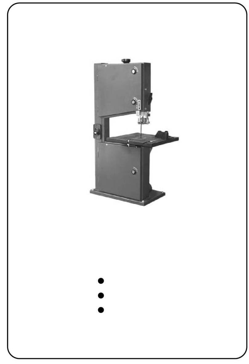
Figure A Figure B Figure C FigureD Figure E Figure F
p.6
1. Always wear gloves when handing saw blade. The operator shall not wear gloves when operating the
machine.
2. All doors shall be closed, all panels replaced, and other safty guards in place prior to the machine being
started or operated. See Figure A.
3. Be sure that the blade is not contact with the workpiece when the motor is started. The motor shall be
started and you should allow the saw to come up to full speed before bring the saw blade into contact with
the workpiece.
4. Keep hands away from the blade area. See Figure B.
5. Remove any cut off piece carefully while keeping your hands free of the blade area.
6. Saw must be stopped and electrical supply must be cut off before and blade replacement or adjustment of
blade support mechanism is done, or before any attempt is made to change the drive belts or before any
periodic service or maintenance is performed on the saw.
7. Remove loose performed on the unnecessary workpieces from area before starting machine.
8. Bring adjustable saw guide and hoards as close as possible to the workpiece.
9. Always wear protective eyewear when operating, servicing or adjusting machine. Eyewear shall be impact
resistant, protective safty glasses with side shields complying with European standard. See Figure C.
10. Please wear breathing and hearing protection to operate machine. See Figure D and E.
11. The workpiece, or part being sawed, must be securely clamped before the saw blade enters the workpiece.
12. Remove cut off pieces carefully, keeping hands away from saw blade and do not smoking. See Figure F.
13. Maintain proper adjustment of blade tension, blade guides and thrust bearings.
14. Do not operate near potentially explosive or other dangerous environment.
15. The measurement of emission sound pressure level is defined according to ISO3746.
SBW-6300 : A weighted sound pressure level measuring under no load at operation position is 68.6dB(A),
and under load at operation position is 76.8dB(A).
The value quoted are emission levels and are not necessarily sate working levels. Whilst there is a
correlation between the emission and exposure levels, this cannot be used reliably to determind whether
or not further precautions are required. Factors that influence the actual level of exposure of the workforce
include the characteristics of the work room, the other sources of noise, etc. i.e. the number of machines
and other adjacent processes. Also the permissible exposure level can very from country to country. This
information, however, will enable the user of the machine to make a better evaluation of the hazard and
risk.
16. The bandsaw equip with two hexagonal spanners to adjust guard for sawblade, should be stop machine
before adjustment.
3.2 Safty instructions

1. Read and understand instruction manual before operation.
2. Please wear goggle, breathing and hearing protection to
operation.
3. Shut down the machine before inspection, maintenance and
adjustment.
4. Be positive that saw blade points downward toward the table.
5. Maintain properadjustment of blade tension, blade guides and
thrust bearings.
6. Adjust upper guide to just clear workpiece.
7. Do not remove jammed cut-off pieces until blade has stopped.
8. Do not operate near potentially explosive or other dangerous
environment.
9. Never open the protective cover or safety guard while the
machine is running.
p.7
3.3 Warning labels & workstation
3.4 Safty working practice
630mm Band Saw
OAV EQUIPMENT & TOOLS, INC.
OAV
MODEL :
VOLTAGE :
CURRENT :
DATE :
SBW-6300
400 V
A
3.75 KW
50 Hz
3
11917 DP
MOTOR :
FREQUENCY :
PHASE :
SERIAL NO. :
NO. 65 TUNG-SHAN ROAD WU-TSO SUBWARD
CHING-SHUI, TAICHUNG,TAIWAN, R.O.C.
TEL:886-4-26201188 FAX: 886-4-26201199
SAW TENSION
1 Safe working practice for all machines
1.1 Straining
When the machine is not in use, for example at the end of a shift, release the sawblade strain and place a
notice on the machine to indicate this and to remind the next user to adjust the strain before starting up.
1.2 Guard removal/replacement
Where guards are removed replace them in accordance with the manufacturer's instructions.
1.3 Machine operation
Never clean the sawblade or band wheel of a band saw using a hand-held brush or scraper whilst the
sawblade is in motion.
1.4 Noise reduction
Regular maintenance of sawblades, extraction system, cleaning and lubrication of the sawblade etc. is
necessary to help control machine noise.
1.5 Operator training
It is essential that operators are adequately trained in the use, adjustment and operation of the machine.
This cover in particular:
a) the principles of machine setting and operation, including the correct use and adjustment of workpiece
holding and guiding devices and guards:
b) the safehanding of the workpiece when cutting:
c) the use of personal protective equipment for ear and eye protection.

p.8
1.6 Tooling
Care should be taken to avoid damaging the sawblade. When not in use, untensioned band sawblades
should be coiled (see figure A. 1) and secured. They should be stored in a safe, dry place. Before use they
should be checked for damaged teeth and cracks.
To avoid craking, tensioned sawblades should be stored in accordance with figure A.2.
At least two operators will be needed to change a wide sawblade.
Suitable carrier equipment should be provided for transporting tensioned wide sawblades ( see figure A.2).
Suitable gloves ( or other handing aids) should be worn whenever sawblades are handled.
1.7 Lighting
It is important to provide adequate lighting around the machine
2 Additional safe working practices for table band saws
2.1 Sawblade thrust wheel
The purpose of the thrust wheel on a table band saw is to give support to the sawblade when cutting ( see
figure 18). Position it just clear of the back of the sawblade when the sawblade running free after being
strained and tracked. Lack of clearance will cause grooving of the thrust wheel and lead to sawblade failure.
2.3 Straight work
Always use a fence for straight cutting, to prevent the workpiece rocking or sliding. ( see figure A.3).
When hand feeling against the fence, it is necessary to use a push stick for feeding close to the sawblade.
Use a demountable power feed device whenever possible with table band saw. Not only are they valuable
aids to safety, but they also increase the output of the machine.
2.4 Diagnol cutting
On machines with a fixed table, firm support should be provided by a means of jig when cutting diagnols
( see figure A.4). It is necessary to use a push stick at the end of the cut.
2.5 Cutting tenons
In the absence of a tenoning machine, a table band saw provides a safe method of cutting tenons (see
figure A.5).
2.6 Wedge cutting
When cutting smallwedges on a table band saw it is necessary to use a guide as shown in figure A. 6.
2.7 Curved and irregular work
When cutting curved or irregular work on a table band saw it is necessary to feed the workpiece forward
every whilst holding it firmly on the table to ensure effective control during cutting and whilst keeping the
hands in a safe position ( see figure A. 7, A. 8). Alternatively a template can be used ( see figure A.9).
For repetition work of curved and irregular shapes, a guide fixed in front of the sawblade can be used in
conjunction with a template to improve safety as well as the speed of operation ( see figure A.9).
NOTE Do not use re-saws for this type of work.
2.8 Cross cutting round stock
It cutting round stock is necessary to secure the workpiece against rotation by using a jig or holder and to use
a sawblade suitable for cross cutting.
2.9 Disc cutting
When disc cutting it is advisable to use a jig as illustrated in figure A.10.
2.10 Operator training
It is essential that all operators are adequately trained in the correct use and adjustment of safety appliances
such as jigs, templates and extension tables.

Figure A.1 - Coiling band saw blade
Figure A.3 - Handling deep work
a) b) c)
p.9
Figure A.3 - Diagonal cutting

Figure A.5 - Cutting tenons Figure A.6 - Cutting wedges
Figure A.6 - Cutting wedges
p.10
Figure A.7 - Handling sharped work
Figure A.8 - Handling curved work
1 Stop clamped to table.

Figure A.9 - Cutting with a template Figure A.10 a) - Fixture without workpiece
Figure A.10 b) - Operator placing workpiece on fixture
p.11
Figure A.10 c) - Machining workpiece
Figure A.10 - Cutting circular work

4.SUPPLIES AND CONSUMPTION
p.12
Caution! Power supply has to be installed by a trained technician.
1. The cross-section of incoming supply protective conductor and each phase conductors must be in accordance
with the following reference of supply conductor table.
Electrical supplies of S-8A: (Frequency 50Hz)
2. It should make sure the machine grounding being connection before connect with power source.
3. The Bandsaw which electric system is provided with an plug, so the customer must connect a suitable power
supply for his own working conditions:
Please used for the electrical power system socket for a 16A plug.
4. SHUT OFF the power, before inspection, maintenance, adjustment and leaving the machine.
5. The minimum cross-sectional area of conductors should be larger than 0.75 mm2inside enclosure, and larger
than 0.75 mm2for cable or 1.0 mm2for single core outside enclosure.
6. The allowable voltage fluctuation range is 610%. If exceed the range, it is necessary to install a voltage
regulator to stabilizer the voltage. The voltage drop from the point of supply to the load of machine will not
exceed 10% of the nominal voltage under normal operating condition.
Model SBW-6300
Voltage 3~, 400V
Recom. Fuse
Cross-section of supply wire(mm2)
PE wire(mm2)
SBW-6300
3~, 400V
≧8A
1.5 mm2
1.5 mm2

5. FRONT SIDE OF BAND SAW
6. FRONT SIDE OF BAND SAW
p.13
CAST IRON WHEEL 630mm
DOOR SAFTY SWITCH
UPPER WHEEL COVER
BREAKING AWITCH ON/OFF
CAST IRON FENCE
LOWER WHEEL COVER
BLADE TRACKING WINDOW
QUICK CHANGE SAW BLADE SYSTEM
QUICK TABLE TIGHTEN HANDLE
POSITIVE KNOB
LOCK KNOB
TABLE TILTING DEVICE
MOTTOR
100mm DUST PORT
BLADE TENSION ADJUSTMENT
KNOB
CASTING HANDLE WHEEL
UPPER BALL BEARING
GGUIDE SYSTEM
TABLE
100mm DUST PORT

p.14
Fixed machine:
To ensure sufficient upright stability of the machine and safety, you need to bolt the machine to floor on M16
screw. ( Fig. 1 )
Assemble the machine
(1) Attach the handle ( a, Fig. 2 ) to the hand wheel ( b, Fig. 2 ), Lock the screw then connect to the machine.
(2) To mount table, remove the table insert and table pin from the table, slide the table slot to the saw blade.
Slow moving to the center of table, make sure the table is located to the M10 holes ( Fig. 3 ) and attach the
spring washer then replace table insert and table pin.
(3) Adjust the table until the saw blade in the center of table insert, then locked with screw.
Adjusting 90 degree table stop
(1) Unplug power Cord.
(2) Loosen the quick table tighten handle (Fig. 5 )
(3) Adjust the table degree with patented table tilting mechanism until the table attach the 90 degree table
stopper.
(4) use a protractor placed on the table and against the blade to see if the table is 90 degree.
Assemble the machine
(1) Attach the handle ( a, Fig. 2 ) to the hand wheel ( b, Fig. 2 ), Lock the screw then connect to the machine.
(2) To mount table, remove the table insert and table pin from the table, slide the table slot to the saw blade.
Slow moving to the center of table, make sure the table is located to the M10 holes (Fig. 3) and attach the
spring washer then replace table insert and table pin.
(3) Adjust the table until the saw blade in the center of table insert, then locked with screw.
Adjusting 90 degree table stop
(1) Unplug power Cord.
(2) Loosen the quick table tighten handle (Fig. 5)
(3) Adjust the table degree with patented table tilting mechanism until the table attach the 90 degree table
stopper.
(4) use a protractor placed on the table and against the blade to see if the table is 90 degree.
Assemble rip fence
(1) Attach the ED rail to the table with screw M8.
(2) Setting the fence to the fence body, slide the fence on its guides until it is the required distance from the
blade.
(3) Check the scale, make sure the distance between the edge of the miter slot and both the front and rear of
the rip fence, adjust both distances are equal.
(4) Lock the fence by locking wheel.
Adjust the cutting height
(1) To adjust the cutting height by casting hand wheel (Fig.2), and check the mm/inch dual scale reading.(Fig. 9)
Adjust the tension
Blade tension is set by a spring located tension mechanism on the upper drive wheel, check the level of the
tension device before cutting. The tension for various blade widths are indicated on the window of machine.
(1) To adjust the tension hand wheel in front of table (Fig.10), and check the tension meter on the machine (Fig.11).
7. OPERATING INSTRUCTION

p.15
Blade changing
(1) Unplug power cord.
(2) remove the table insert and table pin.
(3) Loosen the upper & lower blade guide system.
(4) Release the saw blade with quick change saw blade system on the rear of band saw ( Fig.12 ).
(5) take out the saw blade and guide the new one through table slot, place blade in upper and lower blade
guide system.
(6) replace the new blade in the middle of upper and lower wheel.
(you can blade tracking from the tracking window)
(7) replace the table insert and table pin.
(8) to adjust the blade tension if the blade width is different from the old blade.
Adjusting upper and lower blade guide system
(9) Dust collection
The band saw is recommended to connected to dust collector, to attach the 4" hose with steel clamp
( Fig. 15 ).
(10) Miter Gauge
i Placed the miter gauge in he table slot
ii Loosen the clam screw on the miter gauge
iii Adjust the desired angle of cutting
iv Tighten the clamp screw
Fig. 5 Fig. 6
Fig. 7 Fig. 8 Fig. 9 Fig. 11 Fig. 12
Fig. 13 Fig. 14 Fig. 15
Fig. 1 Fig. 2 Fig. 3

S

Assembly of SBW-6300 CE:
Assembly of SBW-6300 CE:Assembly of SBW-6300 CE:
Assembly of SBW-6300 CE:
Key No.
Parts No. Q`TY
1 331051 1
2 136435 1
3 NH162400 1
4 136436 1
5 SJ100400 4
6 WS100000 4
7 135020 1
8 135028 1
9 135022 1
10 135004 1
11 BR000044 4
12 135041 1
13 SR060400 1
14 SH101000 1
15 NH101700 1
16 135011 1
17 SF050200 1
18 ST040200 2
19 998652 2
20 135081 1
21 ST049200 2
22 998628 2
23 MH136002 1
24 SJ080400 1
25 136440 1
26 SS100600 4
27 NH101700 4
28 SR060400 1
29 135041 1
30
31
32 SF050200 2
33
34 136454 1
35
36 136174 1
37 NH040700 2
38 WF040808 4
39 136457 1
40 SP040200 2
41 SR060200 2
KNOB
PAN HEAD BOLT W/FLANGE M5x10
N T M10
M10x30
PLATE
MOTOR
HEX SOCKET BOLT HEAD SCREW
TAPPING SCREW M4x8(B)
KNOB
STRAIN RELIEF
M4x10
M20
N T M10
HEIGHT POINTER
HANDLE
HANDLE
N T
ROTATE SHAFT
KNOB
M10
SPRING WASHER M10
HEX SOCKET BOLT HEAD SCREW
TAPPING SCREW
LOCATE HANDLE
LIMPID PIECE
RIVET
KNOB
M6x20
HEX HEAD BOLT M10x50
HEX SOCKET BOLT
CORD CLAMP
HEX SOCKET BOLT M6x20
SET BOLT
PIECE
1/2"
5HP-4P
M8x20
M16
M10x20
φ3.2x10
PAN HEAD BOLT W/FLANGE M5x10
STEP COVER
PPER WHEEL COVER
DOOR LATCH SWITCH(ASM) AZD-S11
PAN HEAD BOLT M4x10
Parts Name Size
HEX SOCKET BOLT M6x10
N T M4
FLAT WASHER M4xφ8
p.17

Assembly of SBW-6300 CE:
Assembly of SBW-6300 CE:Assembly of SBW-6300 CE:
Assembly of SBW-6300 CE:
Key No.
Parts No. Q`TY
42 136175 1
43 136479 1
44 136413 1
45 136482 1
46 PS031200 1
47 136424 1
48 ST040200 3
49 136427 1
50 136425 1
51 ST040200 4
52 136426 1
53 136478 1
54 135099 1
55 ST039304 2
56 ST040200 4
57 136019 2
58 NH040700 2
59 WF040808 2
60 SF040700 2
61 136401 1
62 IC135040 1
63 136438 1
64 SR080500 1
65 136430 1
66 NL061000 3
67 NH101000 1
68 WF102325 1
69 136441 1
70 SR081000 1
71 NH081300 1
72 136418 2
73 SM059400 8
74 136481 1
75 136455 1
76 136461 1
77 SS050100 1
78 994301 1
79 SS050100 1
80 136480 1
81 136407 1
LOWER WHEEL COVER
SAW BLADE
3TPI
181"/4597±8.46x1"x0.9mm
UPPER WHEEL SLIDING BRACKET
SPRING
PIN φ3x12
MOVING PLATE
TAPPING SCREW M4x10
PRESS PLATE
TENSION POINTER
TAPPING SCREW M4x10
TENSION SCALE
BRAKING SWITCH K400D
SWITCH PLATE
TAPPING SCREW M3.5x12(AB)
TAPPING SCREW M4x10
WIRE CONECTOR 224-201
N T M4
FLAT WASHER M4xφ8
PAN HEAD BOLT W/FLANGE M4x35
MACHINE BODY
SWITCH CORD
LOCATE BLOCK
HEX SOCKET BOLT M8x25
CAM
NYLON N T M6
N T M10
FLAT WASHER M10xφ23
ADJ ST BOLT
HEX SOCKET BOLT M8x50
N T M8
LOCATE PLATE
CONNECTING S NK BOLT M5x16
SPRING
B SHING
PRESS BLOCK
SET BOLT M5x5
BEARING 51201
SET BOLT M5x5
TENSION LINE
BOLT
Parts Name Size
p.18

Assembly of SBW-6300 CE:
Assembly of SBW-6300 CE:Assembly of SBW-6300 CE:
Assembly of SBW-6300 CE:
Key No.
Parts No. Q`TY
82 136447 1
83 SR060500 1
84 136433 1
85 136444 2
86 SR080400 2
87 136442 1
88 SS109400 1
89 136443 1
90 136451 1
91 BB630603 4
92 136499 2
93 136439 1
94 136464 1
95 136444 3
96 WS080000 3
97 SR080400 3
98 SR069400 2
99 WF061310 2
100
101
102 136463 1
103 136439 1
104 SP069200 6
105 136405 1
106 SS069300 3
107 WF083030 2
108 NH081300 2
109 SR060400 3
110 136562 1
111 136448 1
112 SJ080400 4
113
114 LA340001 2
115 135051 2
116 NL061000 2
117 WF061310 2
118 SR060400 2
119 NL061000 1
120 135051 1
HANDLE WHEEL
HEX SOCKET BOLT M6x25
SQ ARE SHAFT
WASHER
HEX SOCKET BOLT M8x20
PPER WHEEL HINGE(ASM)
SET BOLT M10x16
G IDE BLOCK
PPER WHEEL SHAFT
BALL BEARING 6306LL
PRESSING PLATE
B SHING
PPER WHEEL φ25"
WASHER
SPRING WASHER M8
HEX SOCKET BOLT M8x20
HEX SOCKET BOLT M6x16
FLAT WASHER M6xφ13
LOWER WHEEL φ25"
B SHING
PAN HEAD BOLT M6x8
P LLEY
SET BOLT M6x12
FLAT WASHER M8xφ30
N T M8
HEX SOCKET BOLT M6x20
P LLEY
LOWER SHAFT
HEX SOCKET BOLT HEAD SCREW
M8x20
V-BELT A-34(17-350)
HEX SOCKET BOLT M6x20
BR SH
NYLON N T M6
Parts Name Size
NYLON N T M6
BR SH
FLAT WASHER M6xφ13
p.19

Assembly of SBW-6300 CE:
Assembly of SBW-6300 CE:Assembly of SBW-6300 CE:
Assembly of SBW-6300 CE:
Key No.
Parts No. Q`TY
121
WF061310
1
122
SR060400
1
123
NL061000
1
124
125
AB136488
1
129 WF083030 3
130 WS080000 3
131 SH080400 3
132 SR100600 2
133 WS100000 2
134 WF103030 2
135
136 136449 1
137 SF060200 2
138 136359 3
139 WF062320 3
140 WS060000 3
141 SH060400 3
142 136446 1
143 620021 1
144 SR100700 4
145 WS100000 4
146 WF103030 4
147 AB136421 1
148
149 SP040200 1
150 600058 1
151 136380 1
152 136404 1
153 136434 1
154 AB198110 1set
155 SJ059400 2
156 WS050000 2
157 WF051210 2
158 NF050800 2
169 WF081818 4
170
SJ080600
4
171
FLAT WASHER
M6x
φ13
HEX SOCKET BOLT
M6x20
FENCE ASM
NYLON N T
M6
FLAT WASHER M8xφ30
SPRING WASHER M8
HEX HEAD BOLT M8x20
HEX SOCKET BOLT M10x30
SPRING WASHER M10
FLAT WASHER M10xφ30
BLADE G ADE
PAN HEAD BOLT W/FLANGE M6x10
G ADE PAIL PLATE
FLAT WASHER M6xφ23
SPRING WASHER M6
HEX HEAD BOLT M6x20
HANDLE SHAFT
KNOB
HEX SOCKET BOLT M10x35
SPRING WASHER M10
FLAT WASHER M10xφ30
TR NNION BLOCK(ASM)
PAN HEAD BOLT M4x10
POINTER
G ADE RAIL
TABLE
TABLE INSERT
MITER GA GE ASS`Y
HEX SOCKET BOLT HEAD SCREW
M5x16
SPRING WASHER M5
FLAT WASHER M5xφ12
N T M5
Parts Name Size
M8x30
126~128, empty, no parts.
HEX SOCKET BOLT HEAD SCREW
FLAT WASHER M8xφ18
159~168, empty, no parts.
p.20
Table of contents
Other Carbatec Saw manuals

Carbatec
Carbatec BS-480C User manual

Carbatec
Carbatec SS-400H User manual

Carbatec
Carbatec TS-C250P User manual

Carbatec
Carbatec SS-400C User manual

Carbatec
Carbatec BS-X3453C User manual

Carbatec
Carbatec TS-C250H User manual

Carbatec
Carbatec BS-245H User manual

Carbatec
Carbatec BS-X3452C User manual

Carbatec
Carbatec BS-B200H User manual

Carbatec
Carbatec SS-400C User manual