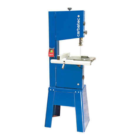
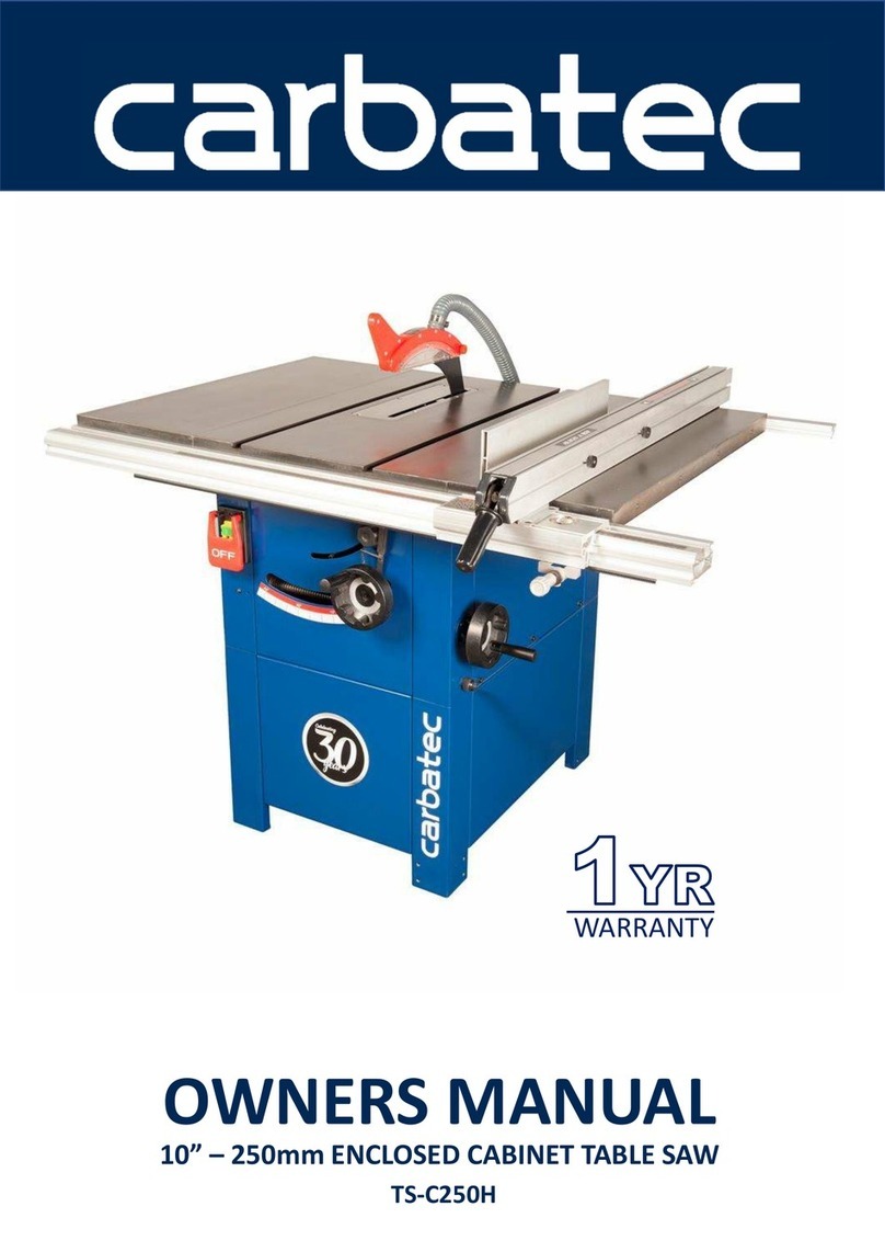
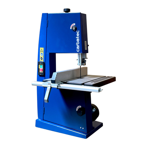
Carbatec BS-345H User manual

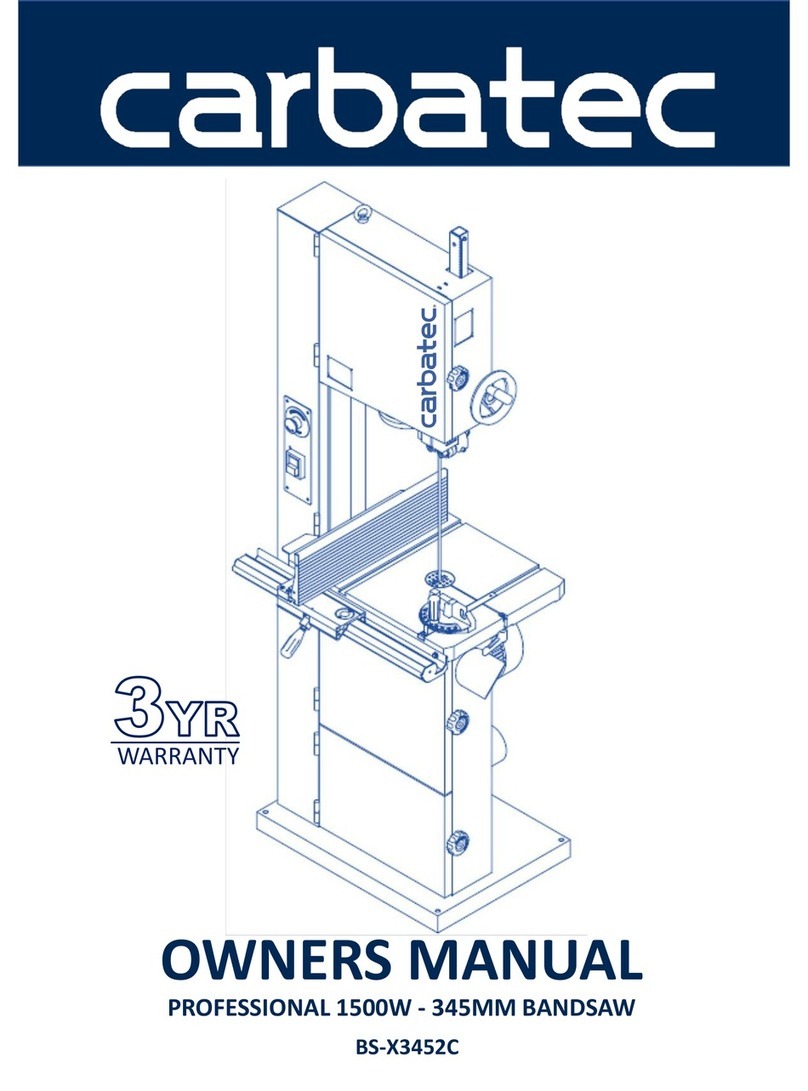
OWNERS MANUAL
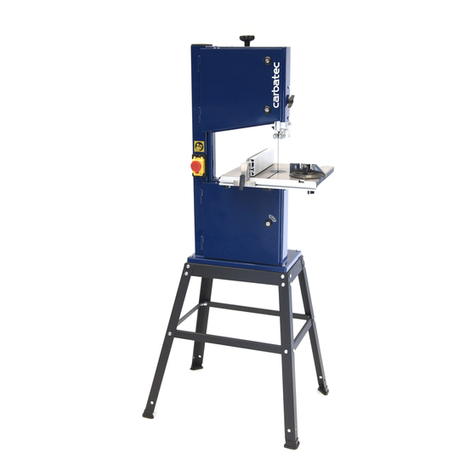
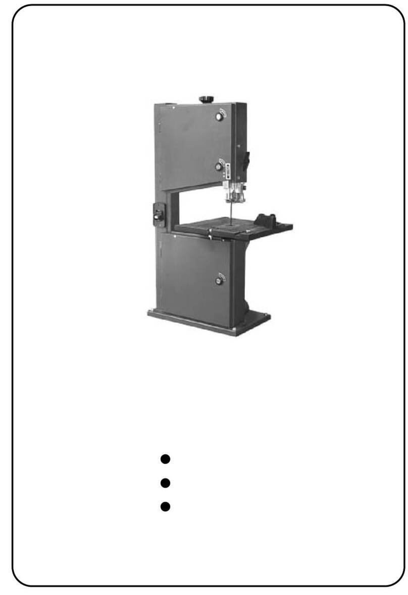
CARBATEC 345mm BANDSAW
BS-345H
WARRANTY

4
General Health & Safety Guidance
Ensure that you carefully read and fully understand the
instructions in this manual before assembly, installation and
use of this product. Keep these instructions in a safe place for
future reference.
WARNING: for your own safety, do not attempt to operate this machine
until it is completely assembled and installed according to
these instructions.
WARNING: When using any machine, basic safety precautions should
always be followed to reduce the risk of fire, electric shock and
personal injury.
Safe Operation
1. Use Personal Protective Equipment (PPE)
•The operation of any machine can result in foreign objects being thrown
into your eyes, which can result in severe eye damage. Protective
eyewear or other suitable eye protection or face shield should be used at
all times. Everyday spectacles only have impact resistant lenses. They are
not protective eyewear and do not give additional lateral protection.
•Use respiratory protective equipment (dust mask etc.) if the machining
operation creates dust. Exposure to high levels of dust created by
machining hardwoods, softwoods and man made composite boards can
result in serious health problems. Some imported hardwoods give off
highly irritating dust, which can cause a burning sensation. The use of
respiratory protective equipment should not be seen as an alternative to
controlling the risk of exposure at source by using adequate dust
extraction equipment.
•The use of ear plugs or ear defenders is recommended when the machine
is in use, particularly if the noise level exceeds 85 dB.
•Wear suitable protective gloves when handling cutting tools or blades.
Gloves should NOT be worn when using the machine as they can be
caught in moving parts of the machine.
•Non-slip safety footwear is recommended when using the machine and
handling large work pieces.
2. Dress appropriately
•Do not wear loose clothing, neckties or jewellery; they can be caught in
moving parts of the machine.
• Roll up long sleeves above the elbow.
• Wear protective hair covering to contain long hair.
3. Safety warnings
• Find and read any warning labels on the machine.
•It is important that any labels bearing health and safety warnings are
not removed, defaced or covered. Replacement labels can be obtained by
contacting our Customer Service Department.
4. Familiarise yourself with the machine
•If you are not thoroughly familiar with the operation of this machine,
obtain advice from your supervisor, instructor, or other qualified person or
contact your retailer for information on training courses. Do not use this
machine until adequate training has been undertaken.
5. Take care when moving or positioning the machine
•Some machines can be very heavy. Ensure the floor of the area in which
the machine is to be used is capable of supporting the machine.
•The machine and its various components can be heavy.
Always adopt a safe lifting technique and seek assistance when lifting
heavy components. In some cases it may be necessary to use mechanical
handling equipment to position the machine within the work area.
•Some machines have optional wheel kits available to allow them to be
manoeuvred around the workshop as required. Care should be taken to
install these according to the instructions provided.
•Due to the nature of the design of some machines the centre of gravity
will be high making them unstable when moved. Extreme care should be
taken when moving any machine.
• If transportation of the machine is required then all precautions relating
to the installation and handling of the machine apply. In addition, ensure
that any vehicles or manual handling equipment used for transportation
are of adequate specification.
6. The machine should be level and stable at all times
•When using a leg stand or cabinet base that is designed to be fitted to
the machine, always ensure that it is securely fastened to the machine
using the fixings provided.
•If the machine is suitable to be used on a workbench, ensure that the
workbench is well constructed and capable of withstanding the weight
of the machine. The machine should always be securely fastened to the
workbench with appropriate fixings.
•Where possible, floor standing machines should always be secured to the
floor with fixings appropriate to the structure of the floor.
•The floor surface should be sound and level. All of the feet of the
machine should make contact with the floor surface. If they do not, either
re-locate the machine to a more suitable position or use packing shims
between the feet and the floor surface to ensure the machine is stable.
7. Remove adjusting keys and wrenches
•Ensure that all adjusting wrenches and keys are removed before
switching the machine ‘ON’. There is a risk of severe personal injury or
damage to the machine from airborne objects.
8. Before switching the machine ‘ON’
• Clear the machine table of all objects (tools, scrap pieces etc.)
•Make sure there is no debris between the work piece and the
table / work support.
•Ensure that the work piece is not pressed against, or touching the saw
blade or cutting tool.
•Check all clamps, work holding devices and fences to ensure that they
are secure and cannot move during machining operations.
•Plan the way that you will hold and feed the work piece for the entire
machining operation.
9. Whilst machining
•Before starting work, watch the machine while it runs. If it makes
an unfamiliar noise or vibrates excessively, switch the machine ‘OFF’
immediately and disconnect it from the power supply. Do not restart until
finding and correcting the source of the problem.
10. Keep the work area clear
•Working clearances can be thought of as the distances between
machines and obstacles that allow safe operation of every machine
without limitation. Consider existing and anticipated machine needs,
size of material to be processed through each machine and space for
auxiliary stands and/or work tables. Also consider the relative position of
each machine to one another for efficient material handling. Be sure to
allow yourself sufficient room to safely operate your machines in any
foreseeable operation.
•Cluttered work areas and benches create the risk of accidents. Keep
benches clear and tidy away tools that are not in use.
•Ensure that the floor area is kept clean and clear of any dust and debris
that may create trip or slip hazards.
11. Consider the work area environment
• Do not expose the machine to rain or damp conditions.
•Keep the work area well lit and ensure that there is artificial lighting
available when there is insufficient natural light to effectively light the
work area. Lighting should be bright enough to eliminate shadow and
prevent eye strain.
•Do not use the machine in explosive environments eg. in the presence of
flammable liquids, gases or dust.
•The presence of high levels of dust created by machining wood can
present a risk of fire or explosion. Always use dust extraction equipment
to minimise the risk.
12. Keep other persons away (and pets)
• The machine is designed to be used by one person only.
•Do not let persons, especially children, touch the machine or extension
cable (if used) and keep visitors away from the work area.
•Never leave the machine running unattended. Turn the power supply off
and do not leave the machine unattended until it comes to a

Downloaded from www.Manualslib.com manuals search engine

5
complete stop.
•If the work area is to be left unattended, all machinery should be
switched ‘OFF’ and isolated from the mains power supply.
13. Store machines safely when not in use
•When not in use, machines should be stored in a dry place, out of reach
of children. Do not allow persons unfamiliar with these instructions or
with the machine to operate it.
14. Do not overreach
•Choose a working position that allows your body to remain balanced
and feed the work piece in to the machine without overreaching.
• Keep proper footing and balance at all times.
15. Electrical supply
•Electrical circuits should be dedicated to each machine or large enough
to handle combined motor amp loads. Power outlets should be located
near each machine so that power or extension cables are not obstructing
high-traffic areas. Observe local electrical guidelines for proper
installation of new lighting, power outlets, or circuits.
• The machine must be connected to an earthed power supply.
•The power supply must be equipped with a circuit breaker that provides
short circuit, overload and earth leakage protection.
•The voltage of the machine must correspond to the voltage of the mains
power supply.
•The mains plug fitted to the machine should always match the power
outlet. Do not modify the plug in any way. If a replacement plug is
required it should be fitted by a competent person and of the correct
type and rating for the machine.
•If you are unsure about any electrical connections always consult a
qualified electrician.
16. Avoid unintentional starting of the machine
•Most machines are fitted with a no-volt release (NVR) switch to prevent
unintentional starting. If in doubt always ensure the machine switch
is in the ‘OFF’ position before connecting it to the power supply. This
means the machine will not automatically start up after a power cut or
switching on of the power supply, unless you first reset the start switch.
17. Outdoor use
• Your machine should not be used outdoors.
18. Extension cables
•Whenever possible, the use of extension cables is not recommended.
If the use of an extension cable is unavoidable, then it should have
a minimum core cross section of 2.5 mm²and limited to a maximum
length of 3 metres.
•Extension cables should be routed away from the direct working area to
prevent a trip hazard.
19. Guard against electric shock
•Avoid body contact with earthed or grounded surfaces such as pipes
and radiators. There is an increased risk of electric shock if your body is
earthed or grounded.
20. Always work within the machine’s intended capacities
•Operator safety and machine performance are seriously adversely
affected if attempts to make the machine perform beyond its limits
are made.
21. Do not abuse the power cable
•Never pull the power cable to disconnect it from the power socket.
Always use the plug.
• Keep the power cable away from heat, oil and sharp edges.
• Do not use the power cable for carrying or moving the machine.
22. Secure the work piece
•Ensure that the work piece is securely held before starting to machine it.
•When working within 300 mm of the machining area, always use a push
stick to feed the work piece in to the blade or cutting tool. The push stick
should have a minimum length of 400 mm. If the push stick becomes
damaged, replace it immediately.
•Use extra supports (roller support stands etc.) for any work pieces large
enough to tip when not held down to the table top.
•Do not use another person as a substitute for a table extension, or as
additional support for a work piece that is longer or wider than the basic
table, or to help feed, support, or pull the work piece.
• Do not attempt to machine more than one work piece at a time.
•When feeding the work piece towards the blade or cutting tool never
position your hands in direct line of the cutting path. Avoid awkward
operations and hand positions where a sudden slip could cause your
hand or fingers to move into the machining area.
23. Stay alert
•Safety is a combination of operator common sense and alertness at all
times when the machine is being used.
•Use all machines with extreme care and do not use the machine when
you are tired or under the influence of drugs, alcohol or medication.
24. Use the correct tool for the job
•Do not use the machine for any purpose other than which it
was designed.
•When selecting replacement cutting tools and blades, always ensure that
they are designed to cut the material that you intend to use them for. If
in any doubt seek further advice from the manufacturer.
25. Connect dust extraction equipment
•Always use dust extraction equipment. The dust extractor should be of
suitable size and capacity for the machine that it is connected to and
have a filtration level appropriate to the type of waste being collected.
Refer to the relevant section of the manual for details of the specific dust
extraction requirements for this machine.
•The dust extractor should be switched ‘ON’ before starting the machine
that it is connected to. The dust extractor should be left running for 30
seconds after the last machining operation is complete in order to clear
any residual waste from the machine.
26. Ensure that the machine is correctly guarded
•Never use the machine if any of the standard safety guards and
equipment are removed or damaged.
•Some machines incorporate safety interlocks to prevent the machine
from being used without the guards in place. Never attempt to bypass
or modify the interlocks to allow the machine to be used without the
guards in place.
27. Maintain your machine with care
•This manual gives clear instructions on installation, set up and
operation of the machine and also details any routine and preventative
maintenance that should be performed periodically by the user.
•Remember always to switch off and unplug the machine from the power
supply before carrying out any setting up or maintenance operations.
•Follow any instructions for the maintenance of accessories
and consumables.
•Do not use compressed air to clean the machine. Always use a brush to
dislodge dust in places that are awkward to reach and a dust extractor
to collect the waste.
•Inspect electric cables periodically and, if damaged, have them replaced
by an authorised service facility or qualified electrician.
•Inspect extension cables (if used) periodically and replace if damaged.
28. Keep cutting tools sharp and clean
•Correctly maintained cutting tools are easier to control and less likely
to bind.
•Cutting tools and blades can become hot during use. Take extreme care
when handling them and always allow them to cool before changing,
adjusting or sharpening them.
29. Disconnect the machine from the power supply
•When not in use, before servicing, changing blades etc. always
disconnect the machine from the power supply.
30. Check for damaged parts
General Health & Safety Guidance - cont.
Downloaded from www.Manualslib.com manuals search engine

6
•Before each use of the machine, it should be carefully checked to
determine that it will operate properly and perform its
intended function.
•Check for alignment of moving parts, binding of moving parts, breakage
of parts and any other conditions that may affect the operation of
the machine.
•A guard or other part that is damaged should be properly repaired
or replaced by a qualified person unless otherwise indicated in this
instruction manual.
•Do not use the machine if the switch does not turn the machine ‘ON’
and ‘OFF’.
• Have defective switches replaced by a qualified person.
31. Warning!
•The use of any accessory or attachment, other than those recommended
in this instruction manual, or recommended by our Company may present
a risk of personal injury or damage to the machine and invalidation of
the warranty.
32. Have your machine repaired by a qualified person
•This machine complies with the relevant safety rules and standards
appropriate to its type when used in accordance with these instructions
and with all of the standard safety guards and equipment in place. Only
qualified persons using original spare parts should carry out repairs.
Failure to do this may result in considerable danger to the user and
invalidation of warranty.
33. Caution! Motor may become hot during use
• It is normal for motors on some machines to become hot to the touch
during use. Avoid touching the motor directly when in use.
General Health & Safety Guidance - cont.
Safe Operation
1. Familiarise yourself with the machine
• Machining operations using bandsaws have a history of serious accidents.
Most result from contact with the moving blade while presenting material
to the blade or moving it from the table. Other minor accidents can occur
whilst setting, cleaning, adjusting or maintaining the machine.
• The machine is designed for cutting wood and composite board (plywood,
MDF etc.). Certain plastics can also be cut using a suitable blade.
2. Before switching the machine ‘ON’
• Ensure that the blade is correctly tensioned and aligned on the
bandwheels and the blade guides are correctly adjusted.
• Ensure that the teeth of the blade are pointing downwards.
• Check the condition of the blade to ensure that no teeth are missing,
damaged or deformed and the blade is not cracked or split. If any of
these conditions apply, replace the blade immediately.
• Ensure that the saw blade type and width are suitable for the material to
be cut.
• Check that the blade width is within the minimum and maximum
permitted on the machine and that the thickness of the blade is suitable
for the diameter of the wheel.
• Some machines have more than one cutting speed. For most wood
cutting applications the faster of the speeds should be used.
• Check the condition of the table insert. Replace it immediately if it is
damaged or showing signs of wear.
• Adjust the guard as close as possible to the work piece being cut.
• Check that access doors are fully closed and that the latches are secure.
3. Whilst machining
• Never apply sideways pressure to the blade as this may cause the blade
to break.
• Care must be taken when cutting wood with knots, nails or cracks in
it and / or dirt on it, as these can cause the blade to get stuck. If this
happens, switch the machine ‘OFF’ immediately and follow the procedure
detailed in the manual to remove the blade from the work piece.
•If cutting cylindrical timber use a suitable jig to prevent twisting of the
work piece.
4. This machine falls under the scope of the ‘Health & Safety at Work etc.
Act 1974’, and the ‘Provision & Use of Work Equipment Regulations 1998’.
In addition the elimination or control of risks from wood dust is included in
the above regulations and the ‘Control of Substances Hazardous to Health
(COSHH) Regulations 2002’. We recommend that you study and follow
these regulations.
Further guidance can be found in the ‘Safety in the use of narrow bandsaws
– Woodworking sheet No.31’ and the ‘Safe use of woodworking machinery’
code of practice booklet (L114) published by Health & Safety Executive and
available from their website www.hse.gov.uk.
Additional Health & Safety for Bandsaws
Downloaded from www.Manualslib.com manuals search engine

9
3. Stand & Wheel Kit Assembly
3.1 Stand & Wheel Kit Assembly
CAUTION! The machine is heavy. Additional help or a suitable
lifting device or support will be required for lifting the machine
onto the stand.
The stand and wheel kit comes as a self assembly unit, Fig.3.1.
Stand
1. 2 x Long mid brace supports
2. Medium mid brace support
3. Short mid brace support
4. 2 x Long top brace supports
5. 2 x Short top brace supports
6. 4 x Legs
7. 24 x Stand fixing nuts bolts and washers (each)
8. 4 x Long fixing bolts, nuts and washers
Wheel Kit
9. 8 x Hex bolts
10. 2 x D-Handle brackets
11. 8 x Nylon nuts
12. 8 x Washers
13. D-handle
14. 2 x Fixed wheels
1
3
2
4
5
6
7
Fig.3.1
( x 24 )
i
Kg
i
Kg
9
10
11
12
13 14
8
Downloaded from www.Manualslib.com manuals search engine

10
Fig.3.3
Fig.3.4
Fig.3.5
Fig.3.6Fig.3.2
Fig.3.7
LONG TOP BRACE
SUPPORT
SHORT TOP BRACE
SUPPORTS
LONG MID BRACE
SUPPORT
i
Kg
3. Stand & Wheel Kit Assembly - cont.
SHORT MID
BRACE SUPPORT
Note: When assembling this legstand do
not fully tighten the nuts and bolts until
the assembly is complete.
When fitting the optional pedal wheekit
during initial assembly of the bandsaw,
please do so before attaching the
bandsaw to the leg stand to ensure
greater safety and ease of fitment.
When fitting the optional pedal wheelkit,
the short mid brace support (Fig. 3.7) at
the front of the bandsaw should
be removed.
Please see section 15 for assembly
instructions of the BS350S-W Pedal
Wheel Kit.
3.2 Stand Assembly
1. Locate the first leg and secure it to one of the
long top brace supports using the nuts, bolts and
washers supplied Fig.3.2.
2. In the same way, attach the second leg to the
brace support Fig.3.3.
3. Locate the short top brace supports and fix
them to the legs as shown Fig.3.4.
4. Continue in this way until all of the legs and
top brace supports have been fitted Fig.3.5.
5. The locating holes a third of the way down
each leg are for securing the mid brace supports.
Fix the long mid brace supports to the frame
using the nuts, bolts and washers Fig.3.6.
6. Finally, fit the short and medium mid brace
supports to the shorter sides Fig.3.7. The short
mid brace support is fitted to holes positioned
two thirds of the way up each leg. The medium
mid brace support is positioned in the lower
holes in each leg.
Downloaded from www.Manualslib.com manuals search engine

12
3. Stand & Wheel Kit Assembly - cont.
3.4 Fitting the bandsaw to the stand
CAUTION! The machine is heavy.
Additional help or a suitable lifting
device or support will be required for
lifting the machine onto the stand.
1. Lift the bandsaw over the stand. and place
the long fixing bolts through the four location
holes in the bandsaw base Fig.3.11.
2. Secure the bandsaw to the stand with the
remaining washers and nuts Fig.3.12.
Fig.3.10
Fig.3.12
Fig.3.11
LONG FIXING BOLTS
1. Feed the long fixing bolts up through the
stand and secure the four corners using the
washers and bolts provided Fig.3.10. Once
this is achieved the whole stand can be fully
tightened ready for the bandsaw to be fitted.
LOCATION
HOLES
200mm 17º
WARNING! For your safety only use the
handle to pull the machine. It is unsafe
to push the machine using the handle.
When lifting the stand ensure the front
legs are not raised higher than 200 mm
from the ground (or at an angle of more
than 17º). Fig.3.13.
Ensure the bandsaw is fitted to the stand
so that the wheels are at the rear (spine
end) of the machine.
Fig.3.13
i
Kg
i
Kg
i
Kg
i
Kg
Downloaded from www.Manualslib.com manuals search engine

3. ASSEMBLY
3.1 Initial Assembly
The machine is supplied partly assembled. Prior to
use, the following items have to be fitted.
Bandsaw table, Rip fence guide and Crank handle.
3.2 Fitting the table
Tools Required: - 13mm Wrench
Insert the M8 x 50 coach bolt and square plastic
insert (A) through the slot on the upper trunion
casting (B) and, temporarily, screw on the
winged nut (C) to prevent it falling out. Fig. 1
Fit the upper table trunion casting (B) to the
underside of the bandsaw table (D) using the
4 - M8 x 16 hex head set screws (E) and
washers, Ensuring that the angle tilt scale is
closest to the edge of the table. Fig. 2
Whilst the table is in the upside down position fit
the table stop screw and nut (F) as shown, this
will be adjusted later. Fig. 1
Turn the table over and remove the winged
nut (C) from the trunion coach bolt (A) making
sure the end of the bolt projects down through
the casting. Fig. 3
(Some assistance may be needed for this)
Guide the table and upper trunion on to the
bandsaw lower trunion (G) and ensure the bolt
(A) projecting from the upper trunion is inserted
through it’s corresponding hole in the lower
trunion Fig. 3. When in position re-fit and tighten the
winged nut.
Fit the plastic table insert (H) to the centre of the
table with the angled bevel facing downwards.
Fig. 4
3.3 Fitting the Rip Fence Guide
This instruction assumes that the blade is already
fitted, if not, go to the section headed “ Replacing
the bandsaw blade”.
To fit the Rip Fence Guide (J) attach it to the front
edge of the table with the four winged
screws and washers supplied (K). This will be
adjusted later. Fig 4
-2-
D
B
C
A F EH
Fig. 1
D
B
E
F
Fig. 2
G
A
Fig. 3
K
J
H
Fig. 4

- 3 -
3.4 Fitting the Crank Handle
Tools Required :- Flat bladed screwdriver
10mm wrench
Attach the crank handle (A) to the belt tension
crank arm with the M6 x 55 slotted cheese head
screw and two M6 nuts. Fig. 5
3.5 Assembling the Rip Fence
The rip fence on this bandsaw can be used on
either side of the blade by fixing the rip fence
extrusion (C) to the appropriate side of the rip
fence casting (B). Fig. 6
To assemble the rip fence take the rip fence
casting (B) Fig. 6 and attach it to the bandsaw
table using the M8 x 50 coach bolt and plastic
winged nut. (F) Fig. 6
Fit the rip fence extrusion (C) to the rip fence
casting (B) with the two small knurled knobs and
M6 x 40 coach bolts (D) and use the large knob
(E) for adjustment and to lock in position as shown
in
Fig. 7
3.6 Fence Adjustment
Vertical and horizontal alignment of the rip fence is
made by adjusting the two small knurled knobs (D)
and the large centre knob (E). Fig. 7
The fence should be aligned with the table slots
along its length and adjusted vertically with a
suitable square placed on the table surface.
3.7 Centering the table to the blade
Tools Required:- 13mm wrench
To centre the table to the blade loosen the 4 M8
nuts (G) Fig. 8 which hold the lower trunion to the
machine frame.
Slide the table sideways until the blade is at the
centre of the slot in the table insert.
Re-tighten the 4 nuts making sure the table
remains in its set position.
A
Fig. 5
Fig. 6
C
BD
EF
Fig. 7
F
ED
G
Fig. 8

- 4 -
3.8 Setting the table square to sawblade
Tools Required :- Small 90 º square
(not supplied)
The table can be set at 90º to the sawblade
Fig. 9 by adjusting the table stop screw
underneath the table.
The table stop screw rests on the top of the lower
wheel bandwheel housing. By, first slackening the
locking nut (A) and then adjusting the screw (B)
the table can be set correctly. Re-tighten the
locking nut (A) making sure that the setting is
maintained. Fig. 10
3.9 Adjusting the rip fence guide scale
Tools Required:- 10mm Wrench
Straightedge
To adjust the rip fence scale loosen the four
winged screws (see K Fig. 4) below the table
and move the scale and rip fence guide (C)
Fig. 11 sideways to adjust. Re-tighten the winged
screws when the adjustment is correct.
The adjustment can be checked by setting the
rip fence to a thickness and cutting a test piece.
When the adjustment is correct the thickness of
the test piece will correspond with the rip fence
scale setting.
3.10 Checking the table for flatness
Once the scale is set to the desired position the
table should be checked for flatness. This can be
done by using a steel rule as a straight edge.
The steel rule should be held on the table across
the table slot close to the front edge of the table.
(See Fig. 12)
If the straight edge shows there is a step across
the table slot then the table needs to be adjusted
using the two screws and locking nuts provided for
this purpose, located on the underside of the rip
fence guide, at (D) Fig. 12
Fig. 12
Fig. 9
Fig. 10
Fig. 11
A
B
C
D

- 5 -
3.11 Stability of the bandsaw
Before using the bandsaw, ensure the machines
upright stability is satisfactory.
The bandsaw has four Ø8mm holes (A) Fig. 13 in
it’s base to allow it to be bolted to the floor or a
bench or alternatively to the optional workstand.
3.12 Dust extraction
The machine is fitted with a dust extraction port of
Ø100mm (B) Fig.14
It is recommended that when in use, the machine
is connected to a suitable dust extractor.
The dust extractor used should be able produce
an air speed of approx. 20 m / sec across the
extraction port area.
3.13 Lower blade guard
When open the lower bandwheel door on this
machine the lower blade guard (C) Fig. 15 swings
down.
When the lower door is closed the guard MUST be
raised back to its operating position.
The bandwheel doors MUST be closed at all times
when the machine is being operated.
3.14 Tilting the bandsaw table
To tilt the table to a specific angle.
Ensure the table is clear of loose objects.
Loosen the winged nut (D) Fig. 16 on the lower
trunion, then tilt the table to the angle required
using the scale (E) Fig. 16.
When the required setting is reached re-tighten
the winged nut to lock the table in position.
Note:- When using the table at an angle always
havetheripfenceonthelowersideofthe
table to support the workpiece.
A
B
Fig.13
Fig.14
C
Fig. 15
Fig. 16
D
E

- 6 -
3.15 Replacing the bandsaw blade
1. Isolate the machine from the supply by unplugging the 3 pin plug.
2. Open the top and bottom bandwheel doors by turning the door locks (A) with a flat bladed
screwdriver.
3. Remove the Rip fence guide (B) from the front of the table by releasing the 4 winged
screws (C).
4. Release the blade tension by turning the large knob (D).
5. Remove the sawblade (E) by feeding it through the slot in the table, upper blade guides
and guard and the slot in the spine of the machine taking care not to cut yourself, wear
gloves if necessary.
6. When fitting the new blade ensure the blade teeth are pointing downwards and towards
you at the position where the blade passes through the table.
7. Re-tension the new blade and check the blade tracking by turning the upper wheel by hand.
The blade should run in the centre of the bandwheel. (See Fig. 19)
8. If required adjust the tracking using tracking knob and lock knob (F) Fig. 18 to the rear of
the upper bandwheel housing. When the tracking is correct lock the setting.
9. Re-set the blade guides as described in the section headed “Adjusting the blade guides”
10. Replace the rip fence guide.
11. Close and lock both the bandwheel doors before re connecting the power supply.
81 .giF 71 .giF
F
D
D
A
A
E
B
C
A

- 7 -
3.16 Tracking the Bandsaw blade
Isolate the machine from the supply by unplugging
the mains plug.
Set the tracking of the blade before setting the
blade guides.
Once the blade is fitted and tensioned, track the
blade by turning the upper bandwheel by hand
and adjusting the tracking knob (F) Fig. 18.
The blade should run in the centre of the
bandwheel as shown in Fig. 19.
When the correct adjustment is achieved lock the
tracking knob with the winged nut.
3.17 Adjusting the Blade Guides
Upper Guides
To adjust the upper blade guides, first position
the roller guides (A) Fig.20 relative to the blade
by slackening off the hex. nut (B) Fig. 20 and
moving the guide carrier until the roller guides
(A) are approx. 2mm behind the gullets of the
blade.
Next set the roller guides (A) to within 0.5mm of
the blade by releasing the screw (C) on each
side of the blade. Do not set the guides too close
as this will adversely affect the life of the blade.
Finally adjust the large thrust bearing (D) Fig. 21
to be just clear of the back of the blade by
unlocking the socket cap screw (E) Fig. 21 .
When the correct adjustment is reached lock in
position with socket cap screw (E).
Lower Guides
To adjust the lower blade guides (F) Fig. 22 first
position the guides so that they are approx. 2mm
behind the gullets of the bandsaw blade by
slackening off the nut (G) Fig.22 then moving the
guide carrier casting to the desired position.
Re-tighten the nut (G) to lock in position.
Adjust the guides (F) to within 0.5mm of be blade
by releasing the socket cap (H).
Fig. 19
Fig. 20
Fig. 21
Fig. 22
G
H
F
C
E
D
A
C
B

-8 -
3.18 Adjusting the Cutting Height
To adjust the cutting height release the winged nut
(A) Fig.23 and move the upper blade guide and
guard assembly (B) Fig. 23 so that it provides
approx 2 - 3mm clearance above the workpiece.
When set correctly re-tighten winged nut (A).
Note: The maximum cutting height is 6” (150mm).
3.19 Changing the Blade Speed
The RSBS14 has two blade speeds 440 m/min
(1445 feet/min) for hardwoods, some plastics and
certain non ferrous metals and 900 m/min
(2950 feet/min) for all other timber.
The lower bandwheel (C) Fig. 24 has two, integral,
multi vee form pulleys and the motor shaft has a
twin multi vee form pulley (D) Fig. 24.
The multi vee belt (E) Fig. 24 passes around the
bandwheel pulley, the motor pulley and the plain
tension roller (F) Fig. 24. The belt tension is
released and applied by using the cranked handle
(G) Fig. 24, this moves the tension roller and
allows the speed to be changed.
To change the belt the lower bandwheel must be
removed.
High Speed 900 m/min
Before changing the speed always make sure the
machine has been isolated from the mains supply .
For the high speed the belt should be fitted to the
rear pulley on both the motor and bandwheel.
As shown in Fig. 25.
Low Speed 440 m/min
Before changing the speed always make sure the
machine has been isolated from the mains supply .
For the low speed the belt should be fitted to the
front pulley on both the motor and bandwheel.
As shown in Fig. 26.
Fig. 24
C
DE
F
G
Fig. 25
Fig. 26
B
A
Fig. 23

- 9 -
4. OPERATION
1. The blade cuts on a continuous downstroke.
2. Slowly feed the workpiece towards the blade, putting only light pressure on it.
3. With both hands, firmly hold the workpiece down on the table, and feed it towards the
bladeslowly,usingthepushsticksupplied,keeping your hands away from the blade.
4. For best results the blade must be sharp.
5. Select the right blade for the job, depending on the thickness of the wood and the cut to be
made. The thinner and harder the wood, the finer the teeth of the blade. Use a fine tooth
blade for cutting sharp curves.
6. Use the fence provided to feed the workpiece along the blade slowly and in a straight line.
7. The machine is especially suited for cutting curves, but will also make straight cuts.
8. When cutting, follow the design marked out by pushing and turning the workpiece evenly.
9. Do not attempt to turn the workpiece without pushing it, as this may cause the workpiece to
get stuck, or the blade to bend.
5. MAINTENANCE
CAUTION! BEFORE CLEANING OR CARRYING OUT MAINTENANCE WORK,
DISCONNECT THE MACHINE FROM THE POWER SOURCE (WALL SOCKET).
NEVER USE WATER OR OTHER LIQUIDS TO CLEAN THE MACHINE. USE A BRUSH.
REGULAR MAINTENANCE OF THE MACHINE WILL PREVENT UNNECESSARY PROBLEMS.
1. Keep the table clean to ensure accurate cutting.
2. Keep the outside of the machine clean to ensure accurate operation of all moving parts and
preventexcessivewear.
3. Keep the ventilation slots of the motor clean to prevent it from overheating.
4. Keep the inside (near the saw blade, etc.) clean to prevent accumulation of dust.

- 10 -
6. TROUBLESHOOTING
WARNING: FOR YOUR OWN SAFETY, ALWAYS TURN OFF THE MACHINE AND
UNPLUG BEFORE CARRYING OUT ANY TROUBLESHOOTING.
TROUBLE PROBABLE CAUSE REMEDY
The machine does not work
when switched on.
1. No power supply. - Check the cable for breakage.
- Check the fuse.
2. Defective switch. - Return machine to your local
dealer for repair.
The blade does not move with
the motor running.
1. The blade tension knob has
not been tightened.
- Switch off the motor, tighten the
blade tension knob.
2. The blade has come off
one of the wheels.
- Open the hinged door and
check.
3. The saw blade has broken.
4. The drive belt has snapped.
- Replace the blade.
- Replace the belt.
The blade does not cut in a
straight line.
1. Fence for cutting not used. - Use a fence.
2. Too fast feed rate.
- Put light pressure on the
workpiece. Make sure the blade
does not bend.
3. The blade teeth are dull or
damaged.
- Try a new blade.
4. Blade guides not suitably
adjusted.
- Adjust the blade guides (see
assembly instructions).
The blade does not cut, or
cuts very slowly.
1. The teeth are dull, caused
by cutting hard material or
long use.
- Replace the blade, use a 6 T.P.I.
blade for wood and soft materials.
Use a 14 T.P.I. blade for harder
materials. A 14 T.P.I. blade always
cuts slower due to the finer teeth
and the slower cutting performance.
2. The blade was fitted the
wrong way round.
- Fit the blade correctly.
Sawdust builds up inside the
machine.
This is normal - Clean the machine regularly.
Open the hinged door and
remove the sawdust with a
vacuum cleaner.
Sawdust inside the motor
housing.
- Clean the ventilating slots of the
motor with a vacuum cleaner.
From time to time remove the
sawdust to prevent it from being
sucked into the housing
The machine does not cut at
45oor 90oangles.
1. The table is not at right
angles to the blade.
- Adjust the table.
2. The blade is dull or too
much pressure was put on the
workpiece.
- Replace the blade or put less
pressure on the workpiece.
The blade cannot be properly
positioned on the pulley.
1. The wheels are not in
alignment. Defective bearing.
- Return the machine to your
local dealer for repair.
2. The wheel alignment knob
hasn’t been properly adjusted.
- Adjust the knob (see
instructions).
3. Inferior blade. - Replace the blade.

8. PART LIST
REF. No. DESCRIPTION .oN.FER DESCRIPTION
desinavlag8MtunegnalF561x71gnirpilcriC1
ylbmessarewol-rooD96ylbmessaleehwwasdnabreppU3
gnikcol-fles,4MtunlanogaxeH07tfahsgniraebreppU4
mm4rehsawtalF17tekcarbreirracleehW5
draugedalbwaS2761MrehsawgnirpS6
21x4M-wercslanogaxeH375.1x61M-tunlanogaxeH7
hctiwstlov-oN47noisnetrofwercSlaicepS8
001x8MtlobegairraC5701dRpaco/wkcolratS9
hsurB67001x11niplacirdnilyC01
05x8hsubrecapS77tekcarbnoisneT11
ylbmessaleehwwasdnabrewoL87tesnidetolS21
10108gniraebllabdevoorG97rehsawelddaS31
leehwnoisneT08gnisuohkcoL41
1x21gnirpilcriC18rehsawnolyN51
tfahsgnidilS385.1x22MtunlanogaxeH61
5.1x02M-tunlanogaxeH58kcoleugnoT71
tfahsgniraebrewoL68mm6rehsawkcoldetarreS81
tleb-v-yloP7801x6M-tloblanogaxeH91
yelluptlebrotoM88gnirpsfaeL02
desinavlag61x6M-wercslanogaxeH09ylbmessareppu-rooD12
mm6rehsawgnirpS19gulpollemaL32
mm01rallocteS29bonknoisnetedalB42
8.0x2.01x02rehsawksiD49renoisnetedalB52
knarC59mm8rehsawtalF62
001dRrotcennocnoitcuS6961x8MwercsdaehlanogaxeH72
desinavlag6M-tuntalflanogaxeH001bonkgnikcartedalB82
eldnahknarC1018MtungniW92
55x6MwercspaC201emarftekcarbnoisneT13
~1V042/022wK1rotoM301desinavlag8MtunegnalF23
tesediugniP401wasdnaB-emarF33
troppusediugrewoL50161x2.4wercsgnipatdaehnaP53
reirracecnefpiR901mm5rehsawkcoldetarreS63
desinavlag52x6MwercsbmuhtdelrunK211etalP73
6MtundelrunK31102x8MtlobegairraC83
mm6talfrehsaW411ediugtloB93
04x6MtlobegairraC51102x6M-tloblanogaxeH04
noisurtxeecneF611tekcarbediuG24
ediugtloB711mm6rehsawkcoldetareS34
05x8MtlobegairraC8116MtunlanogaxeH44
elbaT911ylbmessaediugedalbwaS54
tresnielbaT021edilS64
cirtem-elacS321wercstsujdaediuG84
noisurtxereirracecnefpiR42181008gniraebllabdevoorG94
6MtunlanogaxeH521mm6rehsawtalF05
8MtungniW031Roller Guide Bracket15
eceipedilG431llams,ediugtloB35
reppunoinurtelbaT53121x6MtestekcoswercS45
mm8rehsawkcoldetarreS631tfahsediuG55
02x8MwercslanogaxeH731tnuomediugreppU65
rewolnoinurtelbaT041mm8rehsawtalF75
02x5.2x053erytwasdnaB002gnikcolfles,8MtunlanogaxeH85
pac/wrednilyctnuomgniraeB06
64 Bearing mount cylinder
- 12 -

- 13 -
13


Table of contents
Other Carbatec Saw manuals

Carbatec
Carbatec BS-345C User manual

Carbatec
Carbatec SS-400C User manual

Carbatec
Carbatec BS-X3452C User manual

Carbatec
Carbatec BS-530C User manual

Carbatec
Carbatec TS-C250P User manual

Carbatec
Carbatec SS-400C User manual

Carbatec
Carbatec BAS-250C User manual

Carbatec
Carbatec CTH-110L 1PH User manual

Carbatec
Carbatec BS-345C User manual

Carbatec
Carbatec BS-B200H User manual