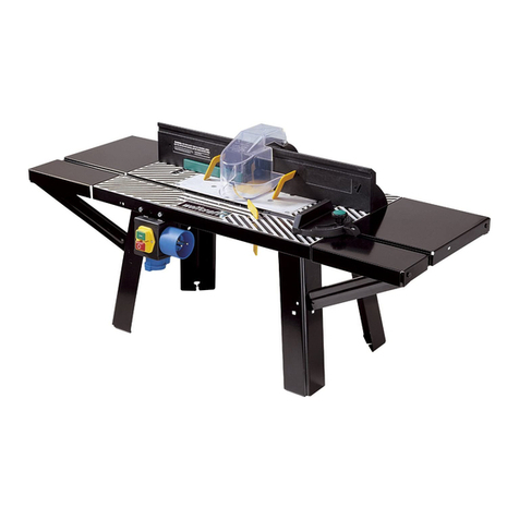
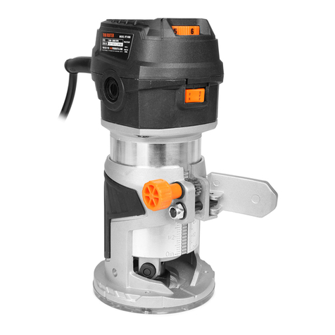
Carbatec SL-660RT User manual

1
3 AXIS-ROUTER TABLE
SL-660RT
MANUAL
Instructions
Maintenance
Assembly
(Router excluded)

2
Content
1. General Safety Rules For All Power Tools…......……………..3-5
2. Specifications………………………………………..……………5
3. Assembly Table Stand…………………...………...………….. .6
4. Assembly Table with Stand…………………….………..………6
5. Assembly Router to Insert……………………..………………..6
6. Assembly Tenoning Jig to Sliding Bracket………………….....7
7. Features & Operational Applications..…….….……………….7-8
8. Router Table Assembly Drawing.……………...……………….9
9. Part List………………………………………..………………10-12
10. Stand Assembly Drawing…….…………….…..………………..13
11. Statement Of Conformity……………………………………….N/A

3
1. General Safety Rules For All Power Tools
1.1READ carefully and thoroughly AND BE FAMILIAR with the owner
operating manual. Learn its limitations and applications and potential
hazards.
1.2ALWAYS KEEP THE GUARD in place and in proper working condition.
1.3GROUND ALL TOOLS. If the tool is equipped with a three pronged
plug, it should always be plugged into a three-hole electrical
receptacle. If an adapter is used for a two-pronged receptacle, the
adapter’s lug must be connected to a known ground cord and NEVER
remove the third prong.
1.4CHECK DAMAGED PARTS. Before further using the tool, any
damaged parts should be checked to assure that it will perform and
operate properly for its intended purposes. Replace and align all
moving parts, mounting, or any other conditions that may affect its
operation.
1.5REMOVE ALL ADJUSTING KEY AND WRENCHES. –Always form the
habit of checking that all keys and adjusting wrenches are removed
from the tool before starting operation.
1.6DISCONNECT UNIT BEFORE SERVICING and when changing blades,
bits or cutters to avoid accidental starting.
1.7KEEP WORKING AREA CLEAN. –Cluttered areas and benches can
cause accidents. Don’t use the unit in damp or wet locations or
expose it to the rain. Also keep the working area well and properly
lighted.
1.8USE SAFETY GLASS AND WEAR PROPER APPAREL –Also use face
or dust mask if the operation is dusty. Wearing loose clothing or
jewelry is not desirable because it may get caught in moving parts.
Put on protecting hair covering to contain long hair.
1.9KEEP CHILDREN AND VISITIORS AWAY. –All visitors should be kept

4
at a safe distance away from the working area, especially while
operating tools.
1.10MAKE WORKSHOP SAFE PROOF. Lock tools when not in use by
removing starter keys or the master switches.
1.11DON’T FORCE THE TOOL. –It will perform a better and safer job at a
rate for which it was designed. Allow the motor to reach full speed
before cutting.
1.12USE RIGHT AND PROPER TOOL. –Don’t use any other tool
attachment to do a job which is not designed for it.
1.13USE RCOMMENDED ACCESSORIES. –Consult the owner manual for
all recommended accessories. Improper use of the tools may cause
accidents.
1.14MAINTAIN TOOLS IN TIP. –TOP CONDITION. –For safest performance
keep the unit clean. Follow all instruction of lubrication and
changing attachment or accessories.
1.15DON’T EVER OVER REACE. –Keep proper footing and balance of
your body at all time during operation of tools.
1.16SEVURE WORK PROPERLY. –Use vises or clamps to hold work. It is
practical and much safer than using your bare hand.
1.17NEVER LEAVE THE TOOL UNATTENED. –Turn the switch in OFF
position and don’ leave unit until it has completely stopped.
1.18NEVER STAND ON THE TOOL. –Serious injury could occur if the unit
is tipped or if the blade is accidentally contacted.
1.19DIRECTION OF FEED. –Always feed the work piece into the blade
against the rotation of blade or cutters.
1.20DRUGS, ALCOHOL AND MEDICATION. –Never operate tools while
under influence of drugs, alcohol. Or after taking medication.

5
1.21NEVER ATTEMPT to perform an abnormal operation. Don’t try to cut
small pieces. Always use adequate hold-down/pushback, jigs, or
fixtures…etc.
1.22Please always use only the supplied cord with plug for our power
tools, which rated current and the rated power input.
1.23Proper fuse is required for supply & replacement.
**Note: Always KEEP THE MANUAL AND REVIEW IT FROM TIME TO TIME.
REVIEWING THE MANUFAL AND FOLLOWING THE INSTRUCTION WILL
GIVE YOU A CONTIOUS SAFE & PROPER OPERATION.
3-AXIS ROUTER TABLE
SPECIFICATIONS
Model/Item No : SL-660RT
Table Sizes : 26" X 18.5" (665mmX 475mm)
Table Inserts : 11.8" X 9" (300mm X 230mm)
Table Height : 32.3" (320mm)
Table Thickness : 1.5" (38mm)
Table T-Slot : 3/8" X 3/4" (9.5mm X 19mm)
Fence Size : 26.4" X 4.75" (660mm X 121mm)
Dust Hood : 4" (101mm)
Net Weight : 64 KGS
Gross Weight : 68 KGS
Packing Dimension : 35" X 29.13" X 10.23"

6
1. UNPACKAGING CARTON PACKAGE – Please carefully unpack
carton & check all loosed parts are in order per part lists.
2. ASSEMBLY TABLE STAND – Please refer
to picture right for complete table stand
assembly.
3. ASSEMBLY TABLE TOP WITH STAND ASSEMBLY– Fasten 4
table bottom corners by screws with stand.
(4 screw holes in back of table top)
(Complete setup)
4. ASSEMBLY ROUTER TO TABLE INSERT
4.1 Remove insert by unfastened 4 screws on insert top, below Left.
4.2 Attach & secure router ring edge (using sketch router instead on
picture) on 4 clamp pieces by tightened 4 wing nuts, check sketch
picture below Right.
4.3 Table inserts & clamps are applicable for various sizes or brands
of routers. Fitting various motor specifications range from 3/4HP
up to 5HP motor.

7
Left – 4 screws in 4 corners Right – please note router edge & clamp
5. ASSEMBLY TENONING JIG / BRACKET TO SLIDING
BRACKET – Fasten tightly lock bar to tenoning bracket and then
attach to sliding bracket. Be sure to put bearing on trail of fence top.
6. SPECIAL FEATURES AND OPERTIONAL APPLICATIONS
6.1 Fence can move back and forth, traveling 204mm (8 inches) to rear
fence & 230mm to front table edge.
204mm (8 inch) to rear fence
230mm (9 inch) to table edge
(Measuring scale on right side of table edge)
6.2 Design of tenoning jig for working vertically or horizontally.
6.3. Tenoning jig axial slide with fence back and forth moving can work
for dovetail tenoning and various tenoning grooves and heads.
(Actual application examples in pictures for reference.)
Be sure bearing on trail of fence top.
Very easy design to install, setup or
remove for other operational applications

8
(Vertical operation with tenoning jig)
(More other vertical operation with tenoning jig)
(Horizontal operation with miter gauge & anti-kick back kit)
6.4 All cast iron table and fence with sturdy construction and 4 inch
dust hood for conveniently and easily connected with dust
collector.
(All cast iron table & fence) (4 inch dust hood)
6.5 Other special applications of pressure device kit
(Bearing end for shaping application) (Pressure block & anti-kick back kit)

9
7. ROUTER TABLE ASSEMBLY DRAWING

10
8. Parts List
PART NO. DESCRIPTION Q'TY
RT660001 TABLE 1
RT660002 SCALE 1
RT660003 TABLE INSERT 1
RT660004 CARRIAGE BOLT M6×45 4
RT660005 CLAMP PIECES( UPPER ) 4
RT660006 CLAMP PIECES ( LOWER ) 4
RT660007 FLAT WASHER M6×φ19 8
RT660008 NUT M6 7
RT660009 WING NUT M6 4
RT660010 COUNTERSUNK HEAD SCREW M6×20 4
RT660011 GUARD PIECES ( A ) 1
RT660012 GUARD PIECES ( B ) 1
RT660013 EXTENSION WING 1
RT660014 HEX HEAD SCREW M 2
RT660015 LOCK WASHER M10 2
RT660016 FLAT WASHER M10×φ27 2
RT660017 SLIDING ROD 2
RT660018 LOCATED PIECES 1
RT660019 LOCK KNOB M8×25 1
RT660020 HEX. SOCKET CAP SCREW M8×25 1
RT660021 ADJUSTED BRACKET 1
RT660022 SET SCREW M8×10 6
RT660023 FEED ROD 1
RT660024 BUSHING 1
RT660025 HAND WHEEL (塑膠) 2
RT660026 HANDLE 2
RT660027 SET SCREW M6×10 2
RT660028 LOCK HANDLE
RT660029 CATCH NUT
RT660030 CATCH NUT 2
RT660031 FENCE 1
RT660032 SCALE 1

11
PART NO. DESCRIPTION Q'TY
RT660033 POINTER 1
RT660034 PAN HEAD SCREW M6×12 6
RT660035 GUARD PLATE 2
RT660036 HEX. SOCKET CAP SCREW M6×25 4
RT660037 FLAT WASHER M6×φ13 4
RT660038 SLIDING ROD 1
RT660039 SLIDING BRACKET 1
RT660040 BUSHING 2
RT660041 TURNNING BRACKET 1
RT660042 BALL BEARING 6200ZZ 1
RT660043 ADJUSTED SCREW 1
RT660044 NUT M8 1
RT660045 SET SCREW M6×25 1
RT660046 SET SCREW M6×40 2
RT660047 POINTER 1
RT660048 LOCK BAR 1
RT660049 STUD 2
RT660050 WORKING TABLE 1
RT660051 ANGULAR SET PLATE 1
RT660052 BASE PLATE 1
RT660053 LOCATED SCREW 1
RT660054 LOCATED NUT 1
RT660055 BASE PIECES 1
RT660056 HEX. SOCKET CAP SCREW M8×40 2
RT660057 LOCK WASHER M8 2
RT660058 SUPPORT BRACKET 1
RT660059 HEX. SOCKET CAP SCREW M6×20 1
RT660060 LOCK BAR 1
RT660061 SPRING PIN φ10×50 1
RT660062 ADJUSTED BLOCK 1
RT660063 FEED STUD 1
RT660064 CLAMP DISC / BAND 1
RT660065 HEX. SOCKET CAP SCREW M8×40 1
RT660066 FLAT WASHER M8 ×φ30 1
RT660067 GUIDE BAR 1

12
PART NO. DESCRIPTION Q'TY
RT660068 PRESSURE BLOCK BRACKET 1
RT660069 PRESSURE BLOCK 1
RT660070 NUT M8 1
RT660071 PRESSURE SHAFT 1
RT660072 BALL BEARING 6200ZZ 1
RT660073 RETAINING RING S10 1
RT660074 LOCK HANDLE 2
RT660075 CATCH BIT 2
RT660076 CATCH NUT 2
RT660077 ANTI-KICK BACK KIT 1
RT660078 MITER GAUGE 1

13
9. Stand Assembly Drawing
Table of contents