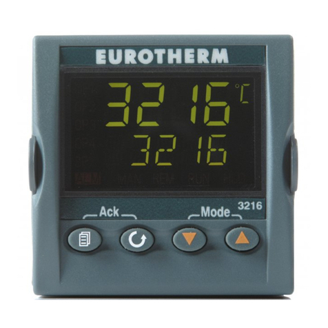
Carbolite 3216CC User manual

LMC20-GB –v1.04
Operating Instructions
Temperature Controller
Type 3216CC
English

2
LMC20-GB –v1’04

3216CC Controller
3
MLC20-GB –v1’04
Contents
1INTRODUCTION TO THE CONTROLLER AND MANUAL 5
1.1 USING THIS MANUAL 5
1.2 PID CONTROL 5
2BASIC OPERATION 6
2.1 CONTROLLER LAYOUT (HOME DISPLAY) 6
2.2 KEYS 6
3QUICK START GUIDE 7
3.1 OPERATION AS A SIMPLE CONTROLLER 7
3.2 CHANGING THE SET POINT 7
3.3 USING THE CONTROLLER 7
3.4 UNDERSTANDING USER LEVELS 7
4SETTING UP THE CONTROLLER 9
4.1 SET POINT RAMP RATE (3216CC ONLY) 9
4.2 MAXIMUM OUTPUT POWER SETTING 9
4.3 CUSTOMER ID. 10
4.4 UNITS 10
4.5 LANGUAGE 10
5TIMER 10
5.1 SETTING THE TIMER 10
5.2 DWELL TIMER 11
5.3 DELAYED SWITCH ON TIMER 11
5.4 SOFT START TIMER 13
6RUNNING A TIMER 14
6.1 DWELL TIMER 14
6.2 DELAYED SWITCH ON TIMER 15
6.3 SOFT START TIMER 17
6.4 ALARMS 19
7OPTIONS 20
7.1 DIGITAL COMMUNICATIONS –RS232 20
7.2 DIGITAL COMMUNICATIONS –RS485 20
7.3 COMMS ADDRESS 21
7.4 ALARM OPTION 21
7.5 REMOTE INPUT AND OUTPUT (ANALOGUE COMMUNICATIONS) 21
8NAVIGATION DIAGRAM 22
8.1 3216CC 22
9CONTROLLER FAULT 23
9.1 FAULT CODE DIAGNOSTIC TABLE 23
10 GLOSSARY OF TERMS 23

4
LMC20-GB –v1’04

Basic Operation
5
LMC20-GB
1 Introduction to the Controller and Manual
1.1 Using This Manual
This manual aims to explain how to set up and operate the Eurotherm 3216CC series of
controllers; it must be read in conjunction with the product main manual.
Due to the complex nature of furnace or oven control the use of technical terms throughout
this manual is unavoidable. Explanations of these terms can be found in the ‘Glossary of
Terms’ at the back of this manual.
This manual covers the operation of:
1.1.1 3216CC - Controller
The 3216CC is a digital temperature controller which uses PID algorithms to give excellent
temperature control when properly set. This controller can only be used as a simple
temperature controller, it cannot be programmed.
1.2 PID Control
The 3216 series of controllers use PID (Proportional Integral Derivative) temperature
control. This type of control uses a complex mathematical control system to adjust the
power being sent to the elements and to hold the furnace or oven at the desired
temperature.

Introduction
6
LMC20-GB –v1’04
2 Basic Operation
2.1 Controller Layout (Home Display)
2.2 Keys
Page Key
The Page key is used to access level 2 when held down
for 3 seconds.
Scroll Key
The Scroll key is used to scroll through the parameters.
ACK
Page + Scroll
When pressed simultaneously the ACK function is used
to:
Return to the Home Menu.
Acknowledge timer end.
Acknowledge an alarm if activated.
Arrow Keys
The arrow keys are used individually to adjust the
selected parameters and in combination to run a program
Note: If a parameter is selected and no further action is taken, the display will time out and
revert back to the home display in its working level after approximately 1 minute
Power Output
Indicator
Scroll Key
Down Key
Up Key
Alarm
Indicator
Hold Indicator
Setpoint
Temperature
Measured
Temperature
Run Indicator
Remote
Indicator
(When configured)
Scroll Key
Page Key

Quick Start Guide
7
LMC20-GB
3 Quick Start Guide
3.1 Operation as a simple controller
When switched on, the controller goes through a short test routine and then shows the
measured temperature (PV = Process Value) in the upper part of the display, and below it,
the set temperature (Set Point).
3.2 Changing the Set Point
Press Up or Down to select the required SP. If the SP is higher than the measured
temperature, the OP1 indicator will illuminate in the top left corner of the display, indicating
that the controller is calling for power (giving an output).
The controller will immediately attempt to reach the set temperature and then maintain it.
3.3 Using the controller
The parameters in the controller are first shown by a short code (mnemonic). After 5
Seconds a description of the parameter will scroll once along the display and then revert
back to the mnemonic. The scrolling text can be interrupted at any time by a single press of
any of the buttons, but will not scroll again until the parameter is returned to. In this manual
the mnemonic will be shown first followed by the scrolling text in brackets;
e.g. WRK.OP <WORKING OUTPUT>
3.4 Understanding User Levels
There are two user levels in the controller; Level 1(Operator) and Level 2 (Supervisor).
Level 1 (Operator) is for the day to day operation of the controller. These parameters are
not protected by a security code.
Level 2 (Supervisor) provides access to additional parameters. Access to these is protected
by a security code
To Enter Level 2
1. Press and hold the page key for 3 seconds.
2. The display will show Leu 1 GOTO
3. Release the page Key
4. Press the Upor Down to choose LEu 2 (level 2)
5. Press the Up or Down to enter the code (Level 2 Code = 9).
If the correct code is entered, the display show the level 2 home display.
If an incorrect code is entered the display reverts back to Level 1 home display

Quick Start Guide
8
LMC20-GB –v1’04
When level 2 operations have been completed, the supervisor must return to Level 1 either
manually or by ‘power cycling’, there is no time out function.
To Return to Level 1
1. Press and hold the page Key
2. Press Down to select LEu 1
It is not necessary to enter a code when going from a higher level to a lower level
when level 1 is selected; the display reverts to the home display (See Section 2.1)
Table showing parameters accessible in level 1 and Level 2
Operator LEVEL 1
Supervisor LEVEL 2
Home display
Home Display
Timer
Timer Status
Alarms (if configured)
Current Transformer Input (if configured)
Comms (if configured)
Controller setup (if configured)
Customer Calibration (if configured)
TIP
If while navigating the controller a parameter has been passed or you need to access
parameters which would be at the end of a scroll list, press and hold Scroll and use Up
to return to a previous parameter.

Operating
9
LMC20-GB
4 Setting up the controller
Before using the controller (or during its lifetime) certain parameters may have to be set,
depending on specific requirements. To do this the controller must be set to supervisor level
(Level 2) see section 3.4
4.1 Set Point Ramp Rate (3216CC only)
To control the rate at which the temperature rises to sepoint, the SP.RATE function is used.
Before setting the ramp rate, it is advisable to set the setpoint to a low value, preferably 0°C
(see section 3.2). Once the ramp rate has been set the required setpoint can be entered
from the home menu. Doing so will activate the ramp rate, which can be identified with the
run indicator showing on the bottom of the display. While the ramp rate is active the working
setpoint will be shown on the lower temperature display (This is the setpoint, set by the
ramp rate).
When the process temperature has reached the setpoint value at the given ramp rate, the
run indicator will turn off and the instrument will control at the required Setpoint temperature.
Any further modifications to set point will cause the ramp rate to be activated and the
instrument to control as described above.
NOTE: Ensure timer configuration is set to ‘none’ (Section 5.1) to use the setpoint ramp rate
feature without any timer functions.
Press scroll until the display shows SP.Rate <setpoint rate limit>. Using Up and
Down select the ramp rate required, in °C/Min.
To check the Setpoint during ramping press the Up or Down once.
To cancel the ramp rate, the SP.Rate <setpoint rate limit> must be set to OFF.
4.2 Maximum Output Power Setting
Press scroll until the display shows OP.HI <Output High>. Using Up and Down
select the output power required as a percentage.
Depending on the furnace or oven model, the maximum output power setting OPHi may be
accessible or locked.
For Silicon Carbide heated furnaces, the parameter is accessible to allow compensation for
element ageing. Refer to the product manual for details.
In many models the maximum output power setting depends on the supply voltage, refer to
the product manual for details.

Operating
10
LMC20-GB –v1’04
4.3 Customer ID.
A furnace or oven identification number can be entered if required. This maybe used to
identify one of many units, for production or quality control systems.
Press scroll until the display shows ID <customer ID>. Using the Up Down enter
your own identification number. This can range from 1-9999.
4.4 Units
Press scroll until the display shows units <Display Units>. Using the Up or Down
select the required units.
Mnemonic
Description
nonE
No units (Default °C)
°C
Celsius
°F
Fahrenheit
°K
Kelvin
PErc
%
4.5 Language
The scrolling text on the 3216 can be shown in different languages, this can only be set at
the factory and therefore must be specified at the time of placing an order.
5 Timer
5.1 Setting the Timer
A timer can be configured to operate in four different modes. These can be selected in level
2 (supervisor level) using the TM.CFG parameter as:-
None
Dwell Timer
Delayed switch on timer
Soft start timer
None
The timer is turned off, no timer configurations are available, the instrument works as a
simple set point controller.
Press scroll until the display shows TM.CFG <TIMER CONFIGURATION>. Using the Up
Down select NONE.

Operating
11
LMC20-GB
5.2 Dwell Timer
A dwell timer is used to control a process at a fixed temperature for a defined period. At the
end of the time period the controller will switch off the output power to the elements.
Press scroll until the display shows TM.CFG <TIMER CONFIGURATION>. Using the Up
Down select Dwel
When Dwell parameter is selected, the Timer resolution (TM.RES), Time duration (DWELL),
Timer threshold (THRES) functions become available.
Press scroll until the display shows TM.RES <Time resolution >. Use the Up Down
to select the timer units in Min or Hours.
Press scroll until the display shows DWELL <SET TIME DURATION >. Use the Up Down
to enter the time duration required.
Press scroll until the display shows THres <TIMER THRESHOLD >. Use the Up Down
to select the temperature threshold that you require the timer to start at.
The threshold value is ±n around the setpoint (n=threshold value).
Example: If the set point is set to 800°C and the timer threshold is set to 2, after the timer is
activated will not start until the process value reaches 798°C if ramping up or 802°C if it is
cooling.
Note: If the threshold is set to OFF, the timer will either; start to count down as soon as it is
activated with the mode keys or if a ramp rate has been set (see section 4.1), the timer will
start as soon as the ramp reaches the set point. (See Section 6.1)
5.3 Delayed Switch On Timer
The delayed switch on timer is used to switch on the output power to the elements after a
set time period.
Press scroll until the display shows TM.CFG <TIMER CONFIGURATION>. Using the Up
Down select dELY
When delay parameter is selected, the Timer resolution (TM.RES), Time duration (DWELL),
functions become available.
Press scroll until the display shows TM.RES <Time resolution >. Use the Up Down
to select the timer units in Min or Hours.

Operating
12
LMC20-GB –v1’04
Press scroll until the display shows DWELL <SET TIME DURATION >. Use the Up Down
to enter the time duration required, before the output power switches on.

Operating
13
LMC20-GB
5.4 Soft Start Timer
The soft start timer is used to start a process at a reduced setpoint and power. The soft start
setpoint is used as a threshold only and is not a control point.
Example: Main Setpoint = 800°C
Max power limit = 75% (This maybe set at the factory)
Soft Start Setpoint = 600°C (Threshold)
Soft Start Power Limit = 50% (Cannot be set above max power Limit)
When the timer is running the maximum power is controlled by the Soft Start Setpoint of
600°C and the Soft Start Power limit of 50%, this will continue until the timer ends or the PV
(Process value) exceeds the Soft Start Setpoint.
When the timer ends or the PV exceed the Soft Start Setpoint the instrument will start to
control using the main Setpoint of 800°C and the Max Power Limit of 75%.
Press scroll until the display shows TM.CFG <TIMER CONFIGURATION>. Using the Up
Down select SF.st
When Soft Start parameter is selected, the Timer resolution (TM.RES), Time duration (DWELL),
Soft Start Setpoint (SS.SP) and Soft Start Power Limit (SS.PWR) functions become available.
Press scroll until the display shows TM.RES <Time resolution >. Use the Up Down
to select the timer units in Min or Hours.
Press scroll until the display shows DWELL <SET TIME DURATION >. Use the Up Down
to enter the time duration required, before the output power switches on.
Press scroll until the display shows SS.SP <Soft Start Setpoint >. Use the Up
Down to enter the soft start setpoint.
Press scroll until the display shows SS.PWR <Soft Start Power Limit >. Use the Up
Down to enter the soft start power limit.

Operating
14
LMC20-GB –v1’04
6 Running a Timer
Run. This starts the timer.
Hold. This stops the timer at the elapsed time. It will start again from the elapsed time when
Run is selected again.
Reset. This sets the timer back to zero. It can be run again from this state.
End cannot be set –it occurs automatically when the timer has counted down to zero.
Acknowledge any timer after a timer has timed out using ACK function (see section 2.2) by
pressing the simultaneously.
6.1 Dwell Timer
Operation
Action
Indication
To RUN Timer
Press and quickly
release +
Indicator –RUN = On
Scrolling Display –Timer Running
To HOLD timer
Press and quickly
release +
Indicator –RUN = Flashing
Scrolling Display –Timer Hold
To switch off
Timer / Cancel
Press and Hold
+ for more than 1
second
Indicator –RUN = Off
Scrolling Display –None
Static Text - OFF
To return to home
after reset
Press and Hold
+ for more than 1
second
Indicator –RUN = Off
Display –A-M
<LOOP MODE- AUTO
MANUAL OFF>
Use the Up Down to select aUTO
Timer Ended
Indicator –RUN = Off
Scrolling Text –Timer End
Static Text - OFF
To re-RUN Timer
Press and quickly
release +
Indicator –RUN = On
Scrolling Display –Timer Running
To RESET timer
and return to home
menu after timer
end
Press and quickly
release
Ack
Indicator –RUN = Off
Scrolling Display - None
Press and Hold
+ for more than 1
second
Indicator –RUN = Off
Display –A-M
<LOOP MODE- AUTO
MANUAL OFF>
Use the Up Down to select aUTO
Power Failure While Using Dwell Timer
If there is a power failure while the timer is running and the power is subsequently restored
the timer will reset and the static text will display “OFF“ until the + keys are pressed to
re-run the timer.

Operating
15
LMC20-GB
Running Dwell Timer with Ramp Rate
Set the ramp rate as outlined in section 4.1
Set the dwell time as outlined in section 5.2
When the timer is set to run with a set ramp rate, the timer will not start to count down until
the setpoint has been reached with the ramp, at which time the timer will begin time count
down.
The scrolling display will indicate “timer running” and the run indicator will be illuminated
while the ramp rate is active and during the timer count down, after which the display will
indicate the instrument has switched off power to the elements (see table 6.1), and the run
indicator will switch off.
Running Dwell Timer with Ramp Rate & Threshold
Set the ramp rate as outlined in section 4.1
Set the dwell time as outlined in section 5.2
Set the threshold as outlined in section 5.2
When the timer is set to run with a set ramp rate and threshold, the timer will not start to
count down until the process temperature has reached the threshold value (see example
section 5.2)
The scrolling display will indicate “timer running” and the run indicator will be illuminated
while the ramp rate is active, while the process value is reaching the threshold value and
during the timer count down, after which the display will indicate the instrument has
switched off power to the elements (see table 6.1).

Operating
16
LMC20-GB –v1’04
6.2 Delayed Switch On Timer
Operation
Action
Indication
To RUN Timer
Press and quickly
release +
Indicator –RUN = On
Scrolling Display –Timer Running
Static Text - OFF
To HOLD timer
Press and quickly
release +
Indicator –RUN = Flashing
Scrolling Display –Timer Hold
Static Text - OFF
To switch off
Timer / Cancel
Press and Hold
+ for more than 1
second
Indicator –RUN = Off
Scrolling Display –None
Static Text - OFF
To return to home
menu. After
Resetting timer.
Press and Hold
+ for more than 1
second
Indicator –RUN = Off
Display –A-M
<LOOP MODE- AUTO
MANUAL OFF>
Use the Up Down to select aUTO
Timer Ended
Indicator –RUN = Off
Scrolling Text –Timer End
To re-RUN Timer
Press and quickly
release +
Indicator –RUN = On
Scrolling Display –Timer Running
Static Text –OFF
Running Delay Timer with Ramp Rate
Set the ramp rate as outlined in section 4.1
Set the delay time as outlined in section 5.3
When ramp rate is active with a Delay timer the run indicator serves two functions:
Indicates timer is running
Indicates ramp rate is active
This means that when the timer has timed out the run indicator will still be illuminated if the
ramp rate is still active and will continue to be illuminated until the ramp reaches setpoint, at
which time it will switch off.
A characteristic of these combinations of parameters is that the scrolling text will continue to
indicate timer running when the timer has timed out. Checking whether the timer has timed
out or not, can be done with the T.REMN function.
The delay timer with ramp rate will function as outlined in the table above with the addition
of the functions in the following table.

Operating
17
LMC20-GB
Delay timer with ramp rate functions
Timer Ended
When ramp rate active
Indicator –RUN = On - if ramp rate active
Scrolling Text –Timer Running
To HOLD timer
Press and quickly
release +
Indicator –RUN = Flashing
Scrolling Display –Timer Hold
Static Text - OFF
To switch off
Timer / Cancel
Press and Hold
+ for more than 1
second
Indicator –RUN = On - if ramp rate active
Scrolling Display –None
Static Text - OFF
To re-RUN Timer
Press and quickly
release +
Indicator –RUN = On
Scrolling Display –Timer Running
Static Text –OFF
Power Failure While Using Delay Timer
If there is a power failure while the timer is running and the power is subsequently restored
the timer will reset and will re-run from the power on time.
6.3 Soft start Timer
Operation
Action
Indication
To RUN Timer
Press and quickly
release +
Indicator –RUN = On
Scrolling Display –Timer Running
Static Text - OFF
To HOLD timer
Press and quickly
release +
Indicator –RUN = Flashing
Scrolling Display –Timer Hold
Static Text - OFF
To switch off
Timer / Cancel
Press and Hold
+ for more than 1
second
Indicator –RUN = Off
Scrolling Display –None
Static Text - OFF
Timer Ended
Indicator –RUN = Off
Scrolling Text –Timer End
Running Soft Start Timer
When the soft start timer is set to run, the scrolling display will indicate “timer running” and
the set point temperature, not the soft start set point.
Power Failure While Using Soft Start Timer
If there is a power failure while the timer is running and the power is subsequently restored
the timer will reset and will re-run from the power on time.
Ramp Rate with Soft Start Timer
It is not recommended that the ramp rate function be used with a soft start timer.
Note: If the temperature is already above the threshold when the timer is set to run the timer
will time out immediately.

Operating
18
LMC20-GB –v1’04

Operating
19
LMC20-GB
Time Remaining
The time remaining of any timer mode can be checked at any time while a timer is active.
To view the time remaining, press scroll until the display
shows T.REMN <TIME REMAINING>.
Note: The time remaining can be modified at any time while the count down timer is running,
by pressing, the Up Down while the time remaining function is active.
6.4 Alarms
Alarms are used to alert the operator when a pre-set level has been exceeded or a function
error has occurred such as a sensor break. They are indicated by a scrolling message on
the display and a flashing red ALM (Alarm) indicator. The alarm may also switch an output –
usually a relay to allow external devices to be operated when an alarm occurs. Alarms only
operate if they have been configured and are dependant on customer requirements.
How to Acknowledge an alarm will depend on the type of latching which has been
configured. A non-latched alarm will reset itself when the alarm condition is removed. A
latched alarm requires acknowledgement with the “ACK” Function (Section 2.2) before it is
reset.
If an alarm has been activated the red “ALM” indicator will light and the scrolling text will
indicate the type of alarm.
To Acknowledge an alarm and cancel the “ALM” indicator, press ACK function.
Note:
The alarm indicator may seem to be permanently on when viewed from above. When an
alarm is active the indicator should only be flashing, to confirm this, the controller must be
viewed directly from the front.

Options
20
LMC20-GB –v1’04
7 Options
Because options can be ordered in a variety of combinations and for a variety of purposes,
exact instructions are not given here. The full Eurotherm manual may be required to
determine customer parameter settings. To reveal or hide parameters in the controller it is
necessary to go into configuration modes and enter a security codes. Please consult
Carbolite Gero.
7.1 Digital Communications –RS232
If the RS232 option is supplied, then the furnace is fitted with one sub miniature D-socket
connected to the controller communications (comms) module. RS232 is suitable for direct
connection to a personal computer (PC), using a “straight through” cable as follows (the
linked pins at the computer end are recommended but may not be necessary). The cable is
usually 9-pin at the furnace end and 9-pin at the computer, but other alternatives are shown
in parentheses.
Furnace end of cable
RS232 Cable: furnace to PC
Computer end of cable
female 9-pin (25-pin)
9-pin (25-pin) male
Rx
3 (2)
3 (2)
Tx
Tx
2 (3)
2 (3)
Rx
Com
5 (7)
5 (7)
Com
7,8 (4,5)
Link
together
1,4,6 (6,8,20)
Link
together
7.2 Digital Communications –RS485
If an RS485 option is supplied, then the furnace is fitted with two sub-miniature D-sockets.
Connection between products is by “straight” cable as follows:
RS485 cable:
furnace to furnace
female 9-pin (25-pin)
9-pin (25-pin) female
3 (2)
3 (2)
+
2 (3)
2 (3)
+
Com
5 (7)
5 (7)
Com
If a boxed KD485 RS485 to RS232 converter is supplied, then the connection cable from
furnace to KD485 should be a “straight” cable, the same as the furnace-to-furnace cable.
The connection between the KD485 and the PC should be a “crossover” cable, the same as
the Furnace to PC cable in section 7.1.
Table of contents
Other Carbolite Temperature Controllers manuals