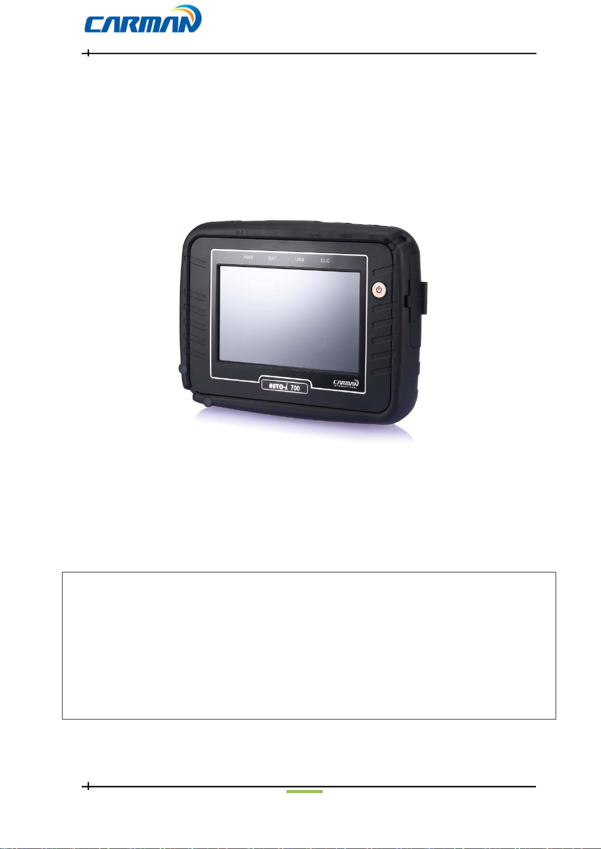
Carman AUTO-i 700 User manual

AUTO-i 700
1
User Guide
Ver. 180719
Safety Cautions
! This information is essential to protect your safety and prevent property damage.
! Make sure to read this thoroughly before using AUTO-i700.
! This information is subject to change or add without notice.
! Please refer to Homepage of CARMAN IT Co., Ltd. for the latest version.
Grade A Equipment (Communication Equipment for business purpose)
Pay attention that this is electromagnetic compatibility equipment for business purpose (Grade A).
It is permitted to use except a house.
CARMAN IT CO., LTD.

AUTO-i 700
2
Table of Contents
Cautions in Use..........................................................................................4
CHAPTER 1General Descriptions...............................................................5
1. Product Features..........................................................5
2. Product Specifications.......................................................6
3. Rechargeable Battery...................................................7
4. Component List..........................................................8
5. Component Figures and Descriptions..........................................................11
6. Power Supply.......................................................24
CHAPTER 2Menu Configuration............................................................25
1. Before Getting Started........................................................................................25
2. Menu Description........................................................................................26
3. Icons..................................................................................27
CHAPTER 3 Configuration....................................................................29
1. Display......................................................................................29
2. Graph........................................................................................30
3. Maker........................................................................................31
4. Time Set............................................................................................32
5. Wi-Fi...........................................................................................33
6. Lock ............................................................................................34
7. Information..........................................................................................36
CHAPTER 4Utility .........................................38
1. Flight Record.....................................................................38
2.TextShot...............................................................................39
3. Screen Capture..............................................................................40

AUTO-i 700
3
Table of Contents
CHAPTER 5Diagnosis Menu...........................................................................42
1. How To Connect Self-Diagnostic Connector and Select
Diagnosis Program.........................................42
CHAPTER 6Vehicle Diagnosis..................................................45
1. Diagnostic Trouble Codes.............................................................................45
2. Erase/reset DTC ...........................................................................48
3. ParameterData.............................................................................49
4. Actuator Test .......................................................................................58
5. Resetting Adaptive Values.............................................................................61
6. EVAP. Leakage Test ..........................................................................62
7. PCM Lock(MEC) Setting........................................................................63
8. Misfire Delay Reason .............................................................................64
9. System Information...........................................................................65
CHAPTER 7OBD-II/EOBD Diagnosis Menu.................................66
1. OBD-II/EOBD Overview....................................................................................66
2. How To Connect Self-Diagnostic Connector and Select Diagnosis Program.....67
CHAPTER 8OBD-II/EOBD Vehicle Diagnosis...............................69
1. Readiness Test ........................................................................69
2. Parameter Data.........................................................................71
3. Diagnostic Trouble Codes...........................................................................73
4. Erase/Reset DTC.........................................................................75
5. Monitoring Test Results..........................................................................76
6. BI-Directional Control...........................................................................79
7. Vehicle Information............................................................................80
CHAPTER 9 Program Download .................................................82
Appendix: Registration.............................................................................89
Q & A.............................................................................90
Certificate of Information and Communication Equipment...................................91
WARRANTY CARD..............................................................................92

AUTO-i 700
4
Cautions in use
Safety Instruction
Cautions in Use
AUTO-i 700 mentioned in this User's Guide is designed for those who have
basic qualifications for using this system.
Users should follow the safety instructions for safe and efficient use of the product.
The cautions of use are as follows:.
- Do not drop AUTO-i 700.
- Always use it in the rubber shroud to product it.
- Do not place AUTO-i 700on the power distributor.
-Although AUTO-i 700 is manufactured to internally prevent the
interference from the electromagnetic waves, the strong interference
by excessive electromagnetic waves may damage the product.
- Excessive surge or electric shock fed by a power cable may damage
the power supply system of AUTO-i 700.
- So, do not use the product while the power supply is unstable.
- The voltage rating of the AC/DC adapter is 12V DC.
- Be sure to use an AC/DC adaptor with the rated voltage.
- Be careful not to let water or oil get into the product.
- The product can be severely damaged.
- Please check if there is short circuit through communication connectors of
OBD-II or a vehicle in the case of flooded cars.
- It can cause damage of scanner.
- Be sure to use the USB cable supplied by CARMAN IT only.
- Otherwise, your PC or product can be damaged.
- Wireless update or wireless communication requires no hurdle between
scanner and wireless devices. Also, it is recommended to communicate within 10 km.

AUTO-i 700
5
Chapter 1: General Descriptions
1. Product Features
AUTO-i 700 can check vehicle ECU information and malfunction status through the
OBD-II/EOBD and MOBD communication.
You can connect AUTO-i 700 to the vehicle diagnostic connector with a diagnosis
cable to check if any of the Engine, Automatic transmission, ABS, Air bag, Power steering
and other devices has an error, view parameter data and use actuator drive features..
AUTO-i 700 has the following features:
▶Diagnosis Korean, Japanese, European and USB vehicles.
- Support OBD-II/EOBD, MOBD
- Support CAN,SAE-J1850,ISO9141-2/KWP2000,J1587
▶Supports vehicle troubleshooting and parameter data search.
- You can diagnose vehicles with their sensors and switches, and save and reload
theparameter data.
▶Supports automatic actuator inspection.
- This function runs/stops the actuator and switches forcibly in order to check if the
corresponding active device is normal..
▶You can use saved data and upgrade the diagnosis program by connecting the product
to your PC with wire or wireless.
▶You can change the sound effects and display unit of the AUTO-i 700.
▶Provides the LCD brightness adjustment function.
▶You can check the latest data and update it automatically.
▶Support real-time screen printing function by wireless.
▶Support Log Data function to save / send the data in the case of communication error so
that fast customer support and newest communication is available.
▶Support remote assistance for usage of product by connecting PC and scanner with USB
connector.

AUTO-i 700
6
Chapter 1: General Descriptions
2. Product Specifications
Item Specification
Dimension 250mm*180mm*40mm
Weight 1.32kg(2.91lb)
CPU OS Windows CE 6.0
Diagnosis Cortex M3 120Mhz
Main Cortex A8 1Ghz
Memory 32GB (Micro SD)
Display 7inch Touch LCD(1024*600)
Operating Temp 0~45℃(32~113℉)
Storage Temp -20~70℃(-4~158℉)
Protocol All Flexibility
- Dual CAN(2.0A,2.0B),Singlewire CAN
- ISO914-2, KWP2000, J1850P, J1587
- K/L-line High Speed Serial, Flashing Code
- Ethernet
Button Power button, All touch button
Operating Voltage 8V ~ 35V
- Please note that if AUTO-i 700 has been under 0℃(32F), it has to stay in
room temperature over 2 hours surely before using it over 0℃.
-If AUTO-i 700 moves from low temperature to room temperature,
condensations inside the device can be generated and it can cause damage
or malfunction.
- So, please do not place this device in the cold if possible.

AUTO-i 700
7
Chapter 1: General Descriptions
3. Rechargeable Battery
* The rechargeable battery pack has the following features
-Voltage of the rechargeable battery pack gradually decreases even when the
system does not run.
- Before using the product for the first time, be sure to fully charge the battery.
- Always use the rechargeable battery pack provided by Our Company.
- Using a 3rd party product may cause explosion.
(7.4V 2200 mAhLithium-Ion battery pack)
- Do not heat the rechargeable battery pack.
- It may cause explosion.
- Do not short the battery pack terminal.
- It may cause explosion.
- Do not place the battery pack on or near hot material over 60ºC.
- It may cause explosion.
- Keep the battery pack away from touch of children or an animal.
- It may cause a fire or injury.
- To prevent the battery pack from being discharged, always connect
the power source before using the system. Screen captures, flight
record and other information can be erased due to the discharged
battery pack..
- The battery is consumable and the warranty period is 6 months from
purchase date.
- If the product is not used over 3 months, the contained battery may be
discharged and swollen.
- Please charge your battery at least once per 2 or 3 month for 24 hours.
.

AUTO-i 700
8
Chapter 1: General Descriptions
4. Component List
1. Basic kit
NO Part No. Description
1 AY-ELPT-A700 AUTO-i 700 Main Body
2 CB-CYAT-0001 DLC Main Cable (16P 2M)
3 CB-CYVG-0006 Cigarette Lighter Power Cable
4 CB-CNHC-0004 Battery Extension Cable
5 PC-02HC-P009 Power adapter (5A)
6 CB-CYTP-0004 AC/DC Power Cord
7 CB-CYAU-001A USB Cable(B Type)
8 LA-MCAU-E001 User Guide
9 LA-DQAU-A001 CD
10 PK-BGTT-0005 Carrying Case
11 FE-MUDE-0046 Wi-Fi USB Dongle

AUTO-i 700
9
Chapter 1: General Descriptions
5. Cable Component
1) Asian kit
NO Part No. Description
1 CB-AYVG-0008 SAMSUNG / NISSAN ADAPTOR (14P)
2 CB-AYHC-0018 KIA ADAPTOR 20P (BLUE)
3 CB-AYVG-0005 DAEWOO,GM ADAPTOR (12P)
4 CB-AYVG-0006 SSANGYONG ADAPTOR (14P)
5 CB-AYVG-0007 SSANGYONG ADAPTOR (20P)
6 CB-AYVG-0001 TOYOTA, LEXUS ADAPTOR (17P"R")
7 CB-AYVG-0002 TOYOTA, LEXUS ADAPTOR (17P"C")
8 CB-AYVG-0009 HONDA ADAPTOR (3P)
9 CB-AYVG-0012 HONDA ADAPTOR (5P)
10 CB-AYVG-0011 SUBARU ADAPTOR (16P-9P)
11 CB-AYVG-0010 MAZDA "C" ADAPTOR (17P)
12 CB-AYVG-0003 MAZDA ADAPTOR (6P + 1P)
13 CB-CYHC-0018 MITSUBISHI ADAPTOR (12P)
14 CB-CYVG-0007 MITSUBISHI CABLE (12P+16P)

AUTO-i 700
10
Chapter 1: General Descriptions
2) European kit
NO Part No. Description
1 CA-PSA1-0002 Peugeot / Citroen Cable (2P)
2 CB-CYHC-0022 Audi / VW Cable (2+2P)
3 CN-T005-AM06 Fiat Cable (3P)
4 CB-AYVG-0014 Opel Adapter (10P)
5 CB-AYVG-0013 BMW Adapter (20P)
3) USA/Australian kit
NO Part No. Description
1 CB-CYHC-0031 Ford Cable (20P)
2 CB-CYVG-0009 Holden Cable (6P)

AUTO-i 700
11
Chapter 1: General Descriptions
6.Component Figures and Descriptions
6-1. User Guide
AUTO-i 700 User Guide
Be sure to read the guide before using the product..
6-2. Main Module
AUTO-i 700 Main Module
* The exterior might be changed without any notice in advance.

AUTO-i 700
12
Chapter 1: General Descriptions
6-3. Connectors and Key
-Connectors on upper right side -- Connectors on upper left side -
①②③④⑤
1. Power connector: It is for a AC/DC power adaptor and a cigar jack.
2. RS-232 connector: It is for the optional product that CARMAN IT sells.
3. RJ45: It is not supported just now. (Later it is supposed to support.)
! Please do not insert a LAN cable.
4. DLC connector: It is for DLC communication cable to diagnose vehicles.
5. Hole for a touch pen: It is for keeping touch pen.
- Connectors on left side -- Connectors on right side -
①②③④⑤⑥
1. Forced Termination: This switch can interrupt power emergently if it is overloaded
while using.
2. USB A Type: Connecting to external device.(Wi-Fi Dongle, USB Memory Stick)
3. HDMI: Connecting to external monitor.
4. USB B TPYE: Connecting to PC for update.
5. USB mini B: USB port for support J2534 communication
(Later, it will be supported on our website.)
6. J2534 power port: power port forJ2534
(Later, it will be supported on our website.)

AUTO-i 700
13
Chapter 1: General Descriptions
6-4. AUTO-i 700 Carrying Case
AUTO-i 700 Carrying Case
AUTO-i 700 includes a number of adaptors and cables for diagnosing vehicles.
When the product is not in use, store it in the supplied carrying case to prevent damage
and loss.
6-5.Touch pen
Picture no.1 Touch Pen Picture no.2 Hole for Touch Pen
You can prevent the touch pen from loss or damage by keeping it into the hole for touch pen
like the picture no.2.

AUTO-i 700
14
Chapter 1: General Descriptions
6-6. Rubber Shroud (fit to the main body initially)
- The color of rubber shroud can be changed according to user
Rubber Shroud
The rubber shroud protects AUTO-i 700 from external electrical and physical impact.
6-7. USB Cable
USB Cable
The USB cable connects the USB ports of AUTO-i700 and your PC to download
the diagnosis software or save captured files to your PC.
- Please use a USB cable for AUTO-i700 only. Other USB cables can
cause contact problem.

AUTO-i 700
15
Chapter 1: General Descriptions
6-8. CD
*Components of CD
- Installation Driver
- PC Program
- PDF Program
- Basic Diagnostic Data
- User Guide
6-9. Wi-Fi USB Dongle
-Newest diagnostic data can be updated automatically via Wi-Fi(USB A Type). Also,
without wire, captured screens in the scanner can be printed via PC that is connected to
a printer.

AUTO-i 700
16
Chapter 1: General Descriptions
6-10. Cigarette Cable
Cigarette Cable
This cigarette cable connects AUTO-i 700 and a vehicle so that it can supply power.
AUTO-i 700 has internal battery inside so it can boot without other power
but if power of batter is low and it is not charged, you can use cigarette
cable or AC/DC power adapter.
6-11. Battery Extension Cable
Battery Extension Cable
This battery extension cable make AUTO-i 700 to get power from battery of a vehicle
directly by connecting to a cigarette cable.

AUTO-i 700
17
Chapter 1: General Descriptions
6-12. DLC Cable
DLC Cable
The DLC cable is also called the OBD-II cable. All vehicles released recently have built-in
OBD-II connectors compatible to the OBD-II specification.
It is possible to diagnose new model vehicles by directly connecting the DLC cable. It is not
necessary to connect any additional power source as power is feed through the diagnostic
connector.
Old model vehicles should be diagnosed by connecting an additional
adapter.
6-13. AC electrical power cord / adapter
AC electrical power cord / adapter
When you want to download the diagnosis program or search flight record, you can use
this AC/DC electrical power adapter to feed power.
Also, can charge the battery built in the product..

AUTO-i 700
18
Chapter 1: General Descriptions
6-14DLC Adapter
The DLC adapter is used to diagnose vehicles by connecting it to the DLC main connector.
As there are similar shaped adapters, make sure to check the vehicle manufacturer name
on the adapter before use.
Also, there can be various adapters for one manufacturer. Therefore, be sure to check the
shape and pin numbers of the diagnostic connector in the vehicle.
Some vehicles do not supply power through the diagnostic connector.
Do not connect any power supply if power can be supplied through the
diagnostic connector..
1) Korean kit
SAMSUNG / NISSAN ADAPTOR (14P)KIA ADAPTOR 20P (BLUE)
DAEWOO,GM ADAPTOR (12P) SSANGYONG ADAPTOR (14P)
SSANGYONG ADAPTOR (20P)

AUTO-i 700
19
Chapter 1: General Descriptions
DAEWOO LPG CABLEHYUNDAI,MITSUBISHI CABLE (12P)
2) Cable for registering trans meter codes to Korean vehicles.
KIA KEYLESS CABLE HYUNDAI KEYLESS CABLE

AUTO-i 700
20
Chapter 1: General Descriptions
3) Japanese kit
TOYOTA, LEXUS ADAPTOR (17P"R")TOYOTA, LEXUS ADAPTOR (17P"C")
HONDA ADAPTOR (3P)HONDA ADAPTOR (5P)
SUBARU ADAPTOR (16P-9P)MAZDA "C" ADAPTOR (17P)
MAZDA ADAPTOR (6P + 1P)NISSAN ADAPTOR (14P)
Other manuals for AUTO-i 700
1
Table of contents
Other Carman Diagnostic Equipment manuals