manuals.online logo
Brands
  1. Home
  2. •
  3. Brands
  4. •
  5. Carrier
  6. •
  7. Air Conditioner
  8. •
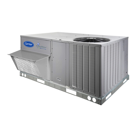
  9. Carrier 50PM20 User manual

Carrier 50PM20 User manual

®
to the Expertg
Installation Instructions
TABLE OF CONTENTS
PAGE
SAFETY CONSIDERATIONS ......................... 1
INSTALLATION .................................... 2
Step 1 - Provide Unit Support ......................... 2
Step 2 - Remove Shipping Rails ....................... 2
Step 3 - Rig and Place Unit ........................... 2
Step 4 - Field Fabricate Ductwork ...................... 9
Step 5 - Make Unit Duct Connections ................... 9
Step 6 - Install Flue Hood and Inlet Hood ............... 10
Step 7 - Trap Condensate Drain ...................... 10
Step 8 - Install Outdoor Air Hood ..................... 24
Step 9 - Position Optional Power Exhaust or
Barometric Relief Damper Hood ...................... 25
Step 10 - Non-Fused Disconnect ..................... 25
Step 11 - Install All Accessories ...................... 26
PRE-START-UP ................................... 26
START-UP ........................................ 27
SERVICE ......................................... 34
TROUBLESHOOTING .............................. 44
APPENDIX A - FAN PERFORMANCE TABLES ........ 47
APPENDIX B - ADDITIONAL START-UP DATA ....... 51
UNIT START-UP CHECKLIST ....................... 54
SAFETY CONSIDERATIONS
Installation and servicing of air-conditioning equipment can be
hazardous due to system pressure and electrical components. Only
trained and qualified service personnel should install, repair, or
service air-conditioning equipment.
Untrained personnel can perform the basic maintenance functions
of replacing filters. All other operations should be performed by
trained service personnel. When working on air-conditioning
equipment, observe precautions in the literature, tags and labels
attached to the unit, and other safety precautions that may apply.
Follow all safety codes. Wear safety glasses and work gloves. Use
quenching cloth for unbrazing operations. Have fire extinguishers
available for all brazing operations.
Recognize safety information. This is the safety-alert symbol /_.
When you see this symbol on the furnace and in instructions or
manuals, be alert to the potential for personal injury.
Understand the signal words DANGER, WARNING, and
CAUTION. These words are used with the safety-alert symbol.
DANGER identifies the most serious hazards which will result in
severe personal injury or death. WARNING signifies a hazard
which could result in personal injury or death. CAUTION is used
to identify unsafe practices which may result in minor personal
injury or product and property damage. NOTE is used to highlight
suggestions which will result in enhanced installation, reliability, or
operation.
UNIT OPERATION AND SAFETY HAZARD
Failure to follow this warning could cause personal
iniury, death and/or equipment damage.
Puron® (R-410A) refrigerant systems operate at higher
pressures than standard R-22 systems. Do not use R-22
service equipment or components on Puron refrigerant
equipment.
ELECTRICALSHOCK HAZARD
Failure to follow this warning could cause personal
iniury or death.
Before performing service or maintenance operations
on unit, turn off main power switch to unit and install
lockout tag. Ensure electrical service to rooftop unit
agrees with voltage and amperage listed on the unit
rating plate.
n
IMPORTANT: []nits have high ambient operating limits. If limits
are exceeded, the units will automatically lock the compressor out
of operation. Manual reset will be required to restart the
compressor.
INSTALLATION
Step 1-- Provide Unit Support
Roof Curb
Assemble or install accessory roof curb in accordance with
instructions shipped with this accessory. (See Fig. 1.) Install
insulation, cant strips, roofing, and counter flashing as shown.
Ductwork can be installed to roof curb before unit is set in place.
Ductwork must be attached to curb and not to unit. Curb must be
level. This is necessary to permit unit drain to function properly.
Unit leveling tolerance is - 1/16-in. per linear ft in any direction.
Refer to Accessory Roof Curb Installation Instructions for
additional information as required.
When accessory roof curb is used, unit may be installed on class A,
B, or C roof covering material. Carrier roof curb accessories are for
flat roofs or slab mounting.
IMPORTANT: The gasketing of the unit to the roof curb is critical
for a watertight seal. Install gasket with the roof curb as shown in
Fig. 1. Improperly applied gasket can also result in air leaks and
poor unit performance. Do not slide unit to position on roof curb.
Alternate Unit Support
When a curb cannot be used, install unit on anoncombustible
surface. Support unit with sleepers, using unit curb support area. If
sleepers cannot be used, support long sides of unit with a minimum
of 3 equally spaced 4-in. x 4-in. pads on each side.
Slab Mount (Horizontal Units Only)
Provide a level concrete slab that extends a minimum of 6 in.
beyond unit cabinet. Install a gravel apron in front of condenser
coil air inlet to prevent grass and foliage from obstructing airflow.
NOTE: Horizontal units may be installed on a roof curb if
required.
Step 2 -- Remove Shipping Rails
Remove shipping rails prior to lowering unit onto roof curb. See
Fig. 2. The rails are attached to the unit at both the return end and
condenser end. Remove the screws from both ends of each rail. Be
careful not to drop the rails onto any surface that could be
damaged. Discard the rails. It is important to replace the screws
into the unit to avoid any air or water leakage.
Step 3 -- Rig and Place Unit
Inspect unit for transportation damage. See Tables 1-3 for physical
data. File any claim with transportation agency.
[]NIT DAMAGE HAZARD
Failure to follow this caution may result in equipment
damage.
All panels must be in place when rigging. Unit is not
designed for handling by fork truck.
Do not drop unit; keep upright. Use spreader bars over unit to
prevent sling or cable damage. Rollers may be used to move unit
across a roof. Level by using unit frame as a reference; leveling
tolerance is - 1/16-in. per linear ft in any direction. See Fig. 3 for
additional information and unit rigging weight.
Four lifting holes are provided in the unit base rails as shown in
Fig. 3. Refer to rigging instructions on unit.
Positionin_
Maintain clearance, per Fig. 4, around and above unit to provide
minimum distance from combustible materials, proper airflow, and
service access.
Do not install unit in an indoor location. Do not locate air inlets
near exhaust vents or other sources of contaminated air.
Although unit is weatherproof, guard against water from higher
level runoff and overhangs.
Roof Mount
Check building codes for weight distribution requirements. Unit
operating weight is shown in Table 1.
Installation Onto Curb
The 50PM units are designed to fit on the accessory full perimeter
curb. Correct placement of the unit onto the curb is critical to
operating performance. To aid in correct positioning, 3/8-in.
diameter locating holes have been added to the unit base rails.
When placing the unit, these holes should line up with the roof
curb edge as shown in Fig. 5 and 6, to assure proper duct opening
alignment. For placement on the curb, use the alignment holes
located approximately 2-in. from the end of the base rail on the
return end of the unit. See labels on the side of the unit for more
details.
[]NIT OR PROPERTY DAMAGE HAZARD
Failure to follow this caution may result in equipment or
property damage.
Do not allow the shipping rail to drop on the roof surface.
Damage to the roof surface may result.
[]NIT DAMAGE HAZARD
Failure to follow this caution may result in equipment
damage,
Do not slide unit to position when it is sitting on the curb.
Curb gasketing material may be damaged and leaks may
result,
ROOFCURB CURB
ACCESSORY HIGHT _ ESCR ) IO
_ -3 //8 I
{997) REF BOT-_
FOP (LANG OPENINGS
<ION)
RTURN
END 3/_' KO -
0'9 _7/16" j
(249) 0<5 1B/16'
(148)
03 1/16'
(78)
BACK
NOTES:
1 ROOFCURB ACCESSORY IS SHIPPED DISASSEMBLED
2 DI_ENSiONS IN ) ARE iN MILLIMEIERS
3 V/!//>B[R£BION OF AIRFLOW
4 ROOF CURB: 16 GA {VA03-56) STEEL
S TO PREVENT -BE HAZARD OF STAGNANT WATER BUILD UP iN THE UNIT
DO NOT EXCEED CURB LEVELING TOLERANCES
B CLEARANCE BETWE[_ UNIT BASE RAiL AND CURB FLANGE IS if4 IN (6 MM)
ON EACH SiDE
MAX CURS LEVELING TOLERANCES:
REIU_R
OPEN NG
CURB
.... 'B'IC,, NO (R}
0 Z S18 22
-167) 9" 6 7116"
(2906)
SUPPEY
OPENNG
CURD
FRONT
PANS {_INI_U_ 20 GAGE STEEl)
_iTH i iNCH FIBERGLASS
INSULATION
ALIGNMENT HOLE
IN BASERAiL OF UB'F'_°_
COUNTER FLASHING--__
(P!ELB SUPPLIED> --------
ROOFING
{FIELD SUPPLIED)
CANT STRiR_
<FIELD SUPPLIED)
ROOFING_ATERML--_
(P_ELU DUPPLIEB_ _
r-BASKET
i (SMPPLIED _ITN
z CURB)
J
i_PLAN VIEW OF ROOFCURB
SECTIONC-C
BACN
REIURR
_ E_b
......... i
V-Z_)oFCURBi
50TG505392 Rev. 2.0
Fig. 1 -Roof Curb Details
C07327
SHIPPING
Fig. 2- Shipping Rail Removal
C06273
CAUTION: NOTICE TO RIGGERS:
ALL PANELS MUST BE IN PLACE WHEN RIGGING.
NOTICE TO RIGGERS: Rig by inserting hooks into unit base rails as shown. Maintain a distance
of 120 inches (3048 MM) from top of unit to eyehook. Leave coil cover attached to unit while
rigging to protect coil of unit from damage.
MAX CENTER or GRAVITY {IN)
UNIT SIZE WEIGHT
(LBS)e X Y Z
PG20 3825 73.0 36.0 30,5
PG24 4075 77,5 36.7 31,0
PG28 4300 70,9 35.1 34,3
'/_ NOTE:
// SEELABELFORUNIT
LOCATIONON ROOFCURB
NOTE
Add i501b (68kg} for domestic crating. 150TG50359214.0
Fig. 3 -Rigging Details
C07241
'..h
iBASERA[L
A_ DORNERi
80" [288] COiL RE_OVAL
REAR3:DE 6"0' [18291 CONDENSERAIR
• 6¸ 6" )19N_] ECONOMIZERRE,OVAL
TOP : 6¸ 0" [/829] CONDENSER):AN
BOTTOM 12 " [SSGI CO,BIStaBLE SURFACE/W/O ClRBI
FORSMALLERSERVICEA_D OPERATIONALCLEARANCES [
CONTACTCARRIEt APPLICATIONE_G_NEERiNGDERAIlmENT i
S DOWNSHOTDUCTSDESiGnERi0 BE _/IACNED _0 ACCESSOR_
RO0_CURBONLY IF UNIT iS MOUNTEDSI_E SUPPLY. IT 1_R3_]_6
IS RECOmmEnDEDT_E DUCTS_USTtE SUPPORTEDBY
CROSSBRACESAS _ONEO_ ACCESSORYROOFCURB¸
DI_ENS}ONSIN ( ] ARE IN _ILLI_ETERS OR K_LOGRA_S
WiTH THEEXCEPTIONO_ CLEARANCE_ORTHECONDENSERCO_L
ANDT_E DAMPER/POWEREXHAUSTAS STATEDI_ NOTE_3. A
REMOVABLE_ENR[ OR BARRICADEREOUIRESNO CLEARANCE
U D_ENSIONS ARE_tOM OUTS_OEOF BASE RAIL¸
ALLO_ 0¸ 5//6 18] ON EARNSIDE _OR TOPCOVERDRiPEDGE 4_¸ 5/8
9 A F_ELDSURPL_ED_0° ELBOWDUCT_USTBE INSTALLED_N TIE _08i1
SUPPLYNRDTWOR_BELO_TIE UNIT DISCHAtGERONNERT_O_
"'|D_DIRECFTON OF A]RELOW
CENTER OF GRAVITY
B"KO {76} _
(TMRU THE CURB R@ER)
I _ 3/4"B 0 {44]
(T_RU THE CURt POWER/
(786}
CONTROLBOX/ ÷
COMPRESSOR
ACCESSDOOR
/HINGED)
OUTSIDE AIR '- \
(INCLUDED WITH UNIT) _
t
22 I/2
[572
6
152] Z
9[2i2/9}6 ]
BAROMETRIC REX HOOD/
P@R EXHAUST [0]
OPERA ING POST ON 8 12
<OPTION) [ ]
5v GF COY •
OUTET (OPTION)
INDOOR MOTOR
ACCESS DOOR
IHING£D)
%
Fig. 4 - Base Unit Dimensions
I 50TG505862 Rev 2.0
NON FUSEB D£SCONNECI
HANDLE (OPT]ONBXLD
INSTALL@}
CONDENSATE ADCESS_
DUCTSiZE VIEWA-A
C07347
Table I -Physical Data
UNIT 50PM 20 24 28
NOMINAL CAPACITY (TONS) 18 20 25
VOLTAGE (volts) 208/230 /460 /575 208/230 /460 /575 208/230 /460 /575
OPERATING WEIGHT (Ibe)
Unit* 2216 2269 2389
Economizer 170 170 195
Roof Curb 14-in ... 24-in 305 ... 385 305 ... 385 270 ... 345
REFRIGERANT SYSTEM Puron (410a) ... Balanced-Port TXV with Bypass
2...2 2...2 2...2
13.7 ... 12.0 15.0 ... 15.0 16.7 ... 16.7
Scroll
Copeland 3MA
110...60 110...110 110...110
630+/-10 ... 505+/-20 630+/-10 ... 505+/-20 630+/-10 ... 505+/-20
40 +/- 7 ... 80 +/-7 40 +/- 7 ... 80 +/-7 40 +/- 7 ... 80 +/-7
30 +/-5 ... 45 +/-5 30 +/-5 ... 45 +/-5 30 +/-5 ... 45 +/-5
Microchannel
Outer...Inner Outer...Inner Outer...Inner
1 ... 20 1 ... 20 1 ... 20
52.6 57 65.5
Propeller
4 ... 22 6 ... 22 6 ... 22
14400 21000 21000
0.25 ... 1400 0.25 ... 2100 0.25 ... 2100
1100 1100 1100
Round Tube Plate Fin
Bottom...Top Bottom...Top Bottom...Top
4..15 4..15 4..15
23.1 23.1 28.9
3/4 NPT 3/4 NPT 3/4 NPT
Refrigerant ... Metering Device
# Circuits ... # Comp.
STD Unit Charge A ... B (Ibs)
COMPRESSOR
Oil Type
Oil A... B... C (oz)
HIGH-PRESSURE SWITCH (peig)
Cutout ... Reset (Auto.)
LOW- PRESSURE SWITCH (psig)
Cutout ... Reset (Auto.)
FREEZE PROTECTION THERMOSTAT
Opens... Closes
CONDENSER COIL
Circuit A ... B
Rows... Fins/in.
Face Area (sq ft)
CONDENSER FAN (type)
Quantity...Diameter (in.)
Nominal CFM (Total, all fans)
Motor Hp ... Watts
Nominal RPM
EVAPORATOR COIL
Circuit A ... B
Rows... Fins/in.
Face Area (sq ft)
Condensate drain conn. Size (in.)
EVAPORATOR FAN (see motor & drive tables for more)
Fan Quantity ... Size (in.)
Type Drive
Nominal CFM
Fan Bearing Type
Maximum Fan RPM
Blower Shaft Diameter (in.)
Blower Pulley Type
2 ...15xll
Belt
7200
1400
1.1875
Fixed
2 ...15xll
Belt
8000
Ball- Concentric Lock
1400
1.1875
Fixed
2 ...15xll
Belt
10000
1400
1.1875
Fixed
FILTERS RA Filter # ... size (in) 9 ... 16x25 9 ... 16x25 9 ... 20x25
Economizer CA inlet screen # ... size (in) 3 ... 20x25 3 ... 20x25 3 ... 20x25
Aluminum evaporator coil/aluminum condenser coil with low heat
Table 2 -Fan and Motor Drive Data - Vertical Supply/Return
UNIT 50PM 20 24 28
Voltage (volts) 208/230 and 460 575 208/230 and 460 575 208/230 and 460 575
LOW RANGE
Motor HP 3.7 5 3.7 5 5 5
Motor Nominal RPM 1750 1750 1750 1750 1750 1750
Maximum Continuous BHP 4.26 5.75 4.26 5.75 5.37 /5.75 5.75
Maximum Continuous Watts 3700 5015 3700 5015 4578 /5115 5015
Motor Frame Size 56HZ S184T 56HZ S184T S184T S184T
Motor shaft diameter (in.) 7/8 1 1/8 7/8 1 1/8 1 1/8 1 1/8
Motor Pulley Pitch Diameter Min - Max (in) 2.7 - 3.7 3.7 - 4.7 2.7 - 3.7 3.7 - 4.7 3.7 - 4.7 3.7 - 4.7
Fan RPM Range 685- 939 751 - 954 685- 939 751 - 954 687- 873 687- 873
Blower Pulley Pitch Diameter (in.) 6.8 8.6 6.8 8.6 9.4 9.4
Pulley center line distance (in.) 11.293-13.544 9.81 - 13.055 11.293-13.544 9.81 - 13.055 9.81 - 13.055 9.81 - 13.055
Belt, Quantity_Type_Length (in.) 1..BX38..39.8 1..BX40..41.8 1..BX38..39.8 1..BX40..41.8 1 ..BX41 ..42.8 1..BX41 ..42.8
Speed change per turn - moveable pulley 42 34 42 34 31 31
(RPM)
Moveable pulley maximum full turns 6 6 6 6 6 6
Factory Speed setting (RPM) 812 853 812 853 780 780
MID- LOW RANGE
Motor HP 5 5 5 5 5 5
Motor Nominal RPM 1750 1750 1750 1750 1750 1750
Maximum Continuous BHP 5.37 /5.75 5.75 5.37 /5.75 5.75 5.37 /5.75 5.75
Maximum Continuous Watts 4578 /5115 5015 4578 /5115 5015 4578 /5115 5015
Motor Frame Size S184T S184T S184T S184T S184T S184T
Motor shaft diameter (in.) 1 1/8 1 1/8 1 1/8 1 1/8 1 1/8 1 1/8
Motor Pulley Pitch Diameter Min - Max (in) 3.7 - 4.7 3.7 - 4.7 3.7 - 4.7 3.7 - 4.7 4.8 - 6 4.8 - 6
Fan RPM Range 949-1206 949-1206 949-1206 949-1206 805-1007 805-1007
Blower Pulley Pitch Diameter (in.) 6.8 6.8 6.8 6.8 10.4 10.4
Pulley center line distance (in.) 9.81 - 13.055 9.81 - 13.055 9.81 - 13.055 9.81 - 13.055 9.81 - 13.055 9.81 - 13.055
Belt, Quantity_Type_Length (in.) 1..BX38..39.8 1..BX38..39.8 1..BX38..39.8 1..BX38..39.8 1 ..BX45..46.8 1 ..BX45..46.8
Speed change per turn - moveable pulley 43 43 43 43 34 34
(RPM)
Moveable pulley maximum full turns 6 6 6 6 6 6
Factory Speed setting (RPM) 1078 1078 1078 1078 906 906
MID-HIGH RANGE
Motor HP 7.5 7.5 7.5 7.5 7.5 7.5
Motor Nominal RPM 1750 1750 1750 1750 1750 1750
Maximum Continuous BHP 7.66/8.51 /8.63 8.63 7.66/8.51 /8.63 8.63 7.66/8.51 /8.63 8.63
Maximum Continuous Watts 6458 /7586 7586 6458 /7586 7586 6458 /7586 7586
Motor Frame Size S213T S213T S213T S213T S213T S213T
Motor shaft diameter (in.) 1 3/8 1 3/8 1 3/8 1 3/8 1 3/8 1 3/8
Motor Pulley Pitch Diameter Min - Max (in) 4.8 - 6.0 4.8 - 6.0 4.8 - 6.0 4.8 - 6.0 4.8 - 6.0 4.8 - 6.0
Fan RPM Range 941 - 1176 941 - 1176 941 - 1176 941 - 1176 941 - 1176 941 - 1176
Blower Pulley Pitch Diameter (in.) 8.9 8.9 8.9 8.9 8.9 8.9
Pulley center line distance (in.) 9.025-12.179 9.025-12.179 9.025-12.179 9.025-12.179 9.025-12.179 9.025-12.179
Belt, Quantity_Type_Length (in.) 1..BX42..43.8 1..BX42..43.8 1..BX42..43.8 1..BX42..43.8 1 ..BX42..43.8 1 ..BX42..43.8
Speed change per turn - moveable pulley 39 39 39 39 39 39
(RPM)
Moveable pulley maximum full turns 6 6 6 6 6 6
Factory Speed setting (RPM) 1059 1059 1059 1059 1059 1059
HIGH RANGE
Motor HP 10 10 10 10 10 10
Motor Nominal RPM 1750 1750 1750 1750 1750 1750
Maximum Continuous BHP 9.94/10.45/11.19 11.5 9.94/10.45/11.19 11.5 9.94/10.45/11.19 11.5
Maximum Continuous Watts 8284 /9330 9711 8284 /9330 9711 8284 /9330 9711
Motor Frame Size S215T S215T S215T S215T S215T S215T
Motor shaft diameter (in.) 1 3/8 1 3/8 1 3/8 1 3/8 1 3/8 1 3/8
Motor Pulley Pitch Diameter Min - Max (in) 4.3 - 5.5 4.3 - 5.5 4.3 - 5.5 4.3 - 5.5 4.3 - 5.5 4.3 - 5.5
Fan RPM Range 1014-1297 1014-1297 1014-1297 1014-1297 1014-1297 1014-1297
Blower Pulley Pitch Diameter (in.) 7.4 7.4 7.4 7.4 7.4 7.4
Pulley center line distance (in.) 9.025-12.179 9.025-12.179 9.025-12.179 9.025-12.179 9.025-12.179 9.025-12.179
Belt, Quantity_Type_Length (in.) 2..BX38..39.8 2..BX38..39.8 2..BX38..39.8 2..BX38..39.8 2..BX38..39.8 2..BX38..39.8
Speed change per turn - moveable pulley 47 47 47 47 47 47
(RPM)
Moveable pulley maximum full turns 6 6 6 6 6 6
Factory Speed setting (RPM) 1156 1156 1156 1156 1156 1156
Table 3 - Fan Motor and Drive Data - Horizontal Supply/Return
UNIT 50PM 20 24 28
Voltage (volts) 208/230 and 460 575 208/230 and 460 575 208/230 and 460 575
LOW RANGE
Motor HP 3.7 5 3.7 5 5 5
Motor Nominal RPM 1750 1750 1750 1750 1750 1750
Maximum Continuous BHP 4.26 5.75 4.26 5.75 5.37 /5.75 5.75
Maximum Continuous Watts 3700 5015 3700 5015 4578 /5115 5015
Motor Frame Size 56HZ S184T 56HZ S184T S184T S184T
Motor shaft diameter (in.) 7/8 1 1/8 7/8 1 1/8 1 1/8 1 1/8
Motor Pulley Pitch Diameter Min - Max (in) 2.7 - 3.7 3.7 - 4.7 2.7 - 3.7 3.7 - 4.7 3.7 - 4.7 3.7 - 4.7
Fan RPM Range 685- 939 751 - 954 685- 939 751 - 954 687- 873 687- 873
Blower Pulley Pitch Diameter (in.) 6.8 8.6 6.8 8.6 9.4 9.4
Pulley center line distance (in.) 11.293-13.544 9.81 - 13.055 11.293-13.544 9.81 - 13.055 9.81 - 13.055 9.81 - 13.055
Belt, Quantity_Type_Length (in.) 1..BX38..39.8 1..BX40..41.8 1 ..BX38..39.8 1 ..BX40..41.8 1 ..BX41 ..42.8 1 ..BX41 ..42.8
Speed change per turn - moveable pulley 42 34 42 34 31 31
(RPM)
Moveable pulley maximum full turns 6 6 6 6 6 6
Factory Speed setting (RPM) 812 853 812 853 780 780
MID- LOW RANGE
Motor HP 5 5 5 5 5 5
Motor Nominal RPM 1750 1750 1750 1750 1750 1750
Maximum Continuous BHP 5.37 /5.75 5.75 5.37 /5.75 5.75 5.37 /5.75 5.75
Maximum Continuous Watts 4578 /5115 5015 4578 /5115 5015 4578 /5115 5015
Motor Frame Size S184T S184T S184T S184T S184T S184T
Motor shaft diameter (in.) 1 1/8 1 1/8 1 1/8 1 1/8 1 1/8 1 1/8
Motor Pulley Pitch Diameter Min - Max (in) 3.7 - 4.7 3.7 - 4.7 3.7 - 4.7 3.7 - 4.7 4.8 - 6 4.8 - 6
Fan RPM Range 949-1206 949-1206 949-1206 949-1206 805-1007 805-1007
Blower Pulley Pitch Diameter (in.) 6.8 6.8 6.8 6.8 10.4 10.4
Pulley center line distance (in.) 9.81 - 13.055 9.81 - 13.055 9.81 - 13.055 9.81 - 13.055 9.81 - 13.055 9.81 - 13.055
Belt, Quantity_Type_Length (in.) 1..BX38..39.8 1..BX38..39.8 1 ..BX38..39.8 1 ..BX38..39.8 1 ..BX45..46.8 1 ..BX45..46.8
Speed change per turn - moveable pulley 43 43 43 43 34 34
(RPM)
Moveable pulley maximum full turns 6 6 6 6 6 6
Factory Speed setting (RPM) 1078 1078 1078 1078 906 906
MID-HIGH RANGE
Motor HP 7.5 7.5 7.5 7.5 7.5 7.5
Motor Nominal RPM 1750 1750 1750 1750 1750 1750
Maximum Continuous BHP 7.66/8.51 /8.63 8.63 7.66/8.51 /8.63 8.63 7.66/8.51 /8.63 8.63
Maximum Continuous Watts 6458 /7586 7586 6458 /7586 7586 6458 /7586 7586
Motor Frame Size S213T S213T S213T S213T S213T S213T
Motor shaft diameter (in.) 1 3/8 1 3/8 1 3/8 1 3/8 1 3/8 1 3/8
Motor Pulley Pitch Diameter Min - Max (in) 4.8 - 6.0 4.8 - 6.0 4.8 - 6.0 4.8 - 6.0 4.8 - 6.0 4.8 - 6.0
Fan RPM Range 941 - 1176 941 - 1176 941 - 1176 941 - 1176 941 - 1176 941 - 1176
Blower Pulley Pitch Diameter (in.) 8.9 8.9 8.9 8.9 8.9 8.9
Pulley center line distance (in.) 9.025-12.179 9.025-12.179 9.025-12.179 9.025-12.179 9.025-12.179 9.025-12.179
Belt, Quantity_Type_Length (in.) 1..BX42..43.8 1..BX42..43.8 1 ..BX42..43.8 1 ..BX42..43.8 1 ..BX42..43.8 1 ..BX42..43.8
Speed change per turn - moveable pulley 39 39 39 39 39 39
(RPM)
Moveable pulley maximum full turns 6 6 6 6 6 6
Factory Speed setting (RPM) 1059 1059 1059 1059 1059 1059
HIGH RANGE
Motor HP 10 10 10 10 10 10
Motor Nominal RPM 1750 1750 1750 1750 1750 1750
Maximum Continuous BHP 9.94/10.45 /11.19 11.5 9.94/10.45 /11.19 11.5 9.94/10.45 /11.19 11.5
Maximum Continuous Watts 8284 /9330 9711 8284 /9330 9711 8284 /9330 9711
Motor Frame Size S215T S215T S215T S215T S215T S215T
Motor shaft diameter (in.) 1 3/8 1 3/8 1 3/8 1 3/8 1 3/8 1 3/8
Motor Pulley Pitch Diameter Min - Max (in) 4.3 - 5.5 4.3 - 5.5 4.3 - 5.5 4.3 - 5.5 4.3 - 5.5 4.3 - 5.5
Fan RPM Range 1014-1297 1014-1297 1014-1297 1014-1297 1014-1297 1014-1297
Blower Pulley Pitch Diameter (in.) 7.4 7.4 7.4 7.4 7.4 7.4
Pulley center line distance (in.) 9.025-12.179 9.025-12.179 9.025-12.179 9.025-12.179 9.025-12.179 9.025-12.179
Belt, Quantity_Type_Length (in.) 2..BX38..39.8 2..BX38..39.8 2..BX38..39.8 2..BX38..39.8 2..BX38..39.8 2..BX38..39.8
Speed change per turn - moveable pulley 47 47 47 47 47 47
(RPM)
Moveable pulley maximum full turns 6 6 6 6 6 6
Factory Speed setting (RPM) 1156 1156 1156 1156 1156 1156
ALIGNMENT
HOLE
(IN BASE
EDGEFLANGE _
ALIGNMENT
HOLE SHOULD
LINE UP WITH
ROOF CURB
EDGE FLANGE
C06276
Fig. 5 - Alignment Hole Details
UNIT DAMAGE AND PERSONAL INJURY HAZARD
Failure to follow this warning could cause equipment
damage and/or personal injury.
For vertical supply and return units, tools or parts could
drop into ductwork and cause an injury. Install a
90-degree turn in the return ductwork between the unit
and the conditioned space. If a 90-degree elbow cannot
be installed, then a grille of sufficient strength and
density should be installed to prevent objects from
falling into the conditioned space.
RETURN SUPPLY
OPENING OPENING
CURB CURB
RETURN SUPPLY L
OPENING
ALIGNMENT -_,. _
HOLESFOR
CURB-BOTH _. jJ
SIDES ROOFCURB
Fig. 6 - Alignment Hole Location
C06277
Step 4-- Field Fabricate Ductwork
On vertical units, secure all ducts to roof curb and building
structure. Do not connect ductwork to unit. For horizontal
applications, field-supplied flanges should be attached to
horizontal discharge openings and all ductwork secured to the
flanges. Insulate and weatherproof all external ductwork, joints,
and roof openings with counter flashing and mastic in accordance
with applicable codes.
Ducts passing through an unconditioned space must be
insulated and covered with a vapor barrier.
If a plenum return is used on a vertical unit, the return should be
ducted through the roof deck to comply with applicable fire codes.
A minimum clearance is not required around ductwork. Cabinet
return-air static shall not exceed -.35-in. wg with econonfizer or
.45-in. wg without econonfizer.
These units are designed for a minimum continuous return-air
temperature in heating of 50°F (dry bulb), or an internfittent
operation down to 45°F (dry bulb), such as when used with a night
set-back thermostat.
To operate at lower return-air temperatures, a field-supplied
outdoor-air temperature control must be used to initiate both stages
of heat when the temperature is below 45°F. Indoor comfort may
be compronfised when these lower air temperatures are used with
insufficient heating temperature rise.
Step 5 -- Make Unit Duct Connections
Vertical Configuration
Unit is shipped for thru-the-bottom duct connections. Ductwork
openings are shown in Fig. 1 and 4. Duct connections for vertical
supply and return configuration are shown in Fig. 7.
Field-fabricated concentric ductwork may be connected as shown
in Fig. 8. The unit is designed to attach the ductwork to the roof
curb. Do not attach duct directly to the unit.
Units with electric heat require a I-in. clearance for the first 24 in.
of ductwork. Outlet grilles must not lie directly below unit
discharge.
ECONOMIZER
<37
SEE
NOTE
I#[_ [_ AIR
OUT
NOTE:Donotdrillinthisarea. Damage to basepan mayresultinwaterleak.
C06378
Fig. 7 - Air Distribution - Vertical Supply and Return
ECONOMIZER
SEE
<7>
\\ _\ 1SEE
I\\\ \\\ ,\ //qNOTE
\ X\ /
AIR OUT AIR IN AIR OUT
NOTE: Do not drill in this area. Damage to basepan may result in water leak.
C06379
Fig. 8 -Air Distribution - Concentric Duct
NOTE: A 90-degree elbow must be provided in the supply
ductwork to comply with UL (Underwriters' Laboratories) codes
for use with electric heat.
B
Horizontal Applications
Horizontal units are shipped with outer panels that allow for side
by side horizontal duct connections. If specified during ordering,
the unit will be shipped with the vertical duct openings blocked off
from the factory, ready for side supply installation. If the horizontal
option was not specified at time of ordering the unit, a
field-installed accessory kit is required to convert the vertical unit
into a horizontal supply configuration.
Installation of the duct block-off covers should be completed prior
to placing the unit unless sufficient side clearance is available. A
minimum of 66 in. is required between the unit and any
obstruction to install the duct block-off covers. Side supply duct
dimensions and locations are shown on Fig. 4. Connect ductwork
to horizontal duct flange connections on side of unit.
Step 6-- Trap Condensate Drain
See Fig. 9 for drain location. One 3/4-in. half coupling is provided
outside unit evaporator section for condensate drain connection. A
trap at least 4-in. deep must be used. (See Fig. 10.)
All units must have an external trap for condensate drainage. Install
a trap at least 4 in. deep and protect against freeze-up. If drain line
is installed downstream from the external trap, pitch the line away
from the unit at 1 in. per 10 ft of run. Do not use a pipe size smaller
than the unit connection.
Step 7-- Make Electrical Connections
Field Power Supply
Unit is factory wired for voltage shown on unit nameplate. Be sure
to check for correct voltage.
When installing units, provide disconnect per NEC (National
Electrical Code) of adequate size (MOCP [Maximum
Overcurrent protection] of unit is on the informative plate). (See
Tables 4 and 5.) All field wiring must comply with NEC and local
codes. Size wire based on MCA (Minimum Circuit Amps) on the
unit informative plate. See Fig. 11 for power wiring connections to
the unit power terminal block and equipment grounds.
Route power and ground lines through control box end panel or
unit basepan (see Fig. 4) to connections as shown on unit wiring
diagram and Fig. 12.
UNIT DAMAGE HAZARD
Failure to follow this caution may result in damage to unit.
The correct power phasing is critical to the operation of the
scroll compressors. An incorrect phasing will result in an
alarm being generated and compressor operation lockout.
Should this occur, power phase correction must be made to
the incoming power.
ELECTRICAL SHOCK AND FIRE HAZARD
Failure to follow this warning could result in electrical
shock, fire, or death.
The cabinet MUST have an uninterrupted, unbroken
electrical ground to minimize the possibility of personal
injury if an electrical fault should occur. This ground
may consist of electrical wire connected to unit ground
lug in control compartment, or conduit approved for
electrical ground when installed in accordance with
NEC, ANSI/NFPA (American National Standards
Institute/National Fire Protection Association), latest
edition, and local electrical codes.
Field wiring must conform to temperature limitations for type "T"
wire. All field wiring must comply with NEC and local
requirements.
Operating voltage to compressor must be within voltage range
indicated on unit nameplate. On 3-phase units, voltages between
phases must be balanced within 2%.
Unit failure as a result of operation on improper line voltage or
excessive phase imbalance constitutes abuse and may cause
damage to electrical components.
Field Control Wiring
Unit can be controlled with aCarrier-approved accessory
thermostat. Install thermostat according to the installation
instructions included with accessory. Locate thermostat assembly
or space temperature sensor on a solid interior wall in the
conditioned space to sense average temperature.
Route thermostat cable or equivalent single leads of colored wire
from subbase terminals through conduit into unit to low-voltage
connections as shown on unit label wiring diagram and in Fig. 12.
NOTE: For wire runs up to 50 ft, use no. 18 AWG (American
Wire Gauge) insulated wire (35°C minimum). For 50 to 75 ft, use
no. 16 AWG insulated wire (35°C minimum). For over 75 ft, use
no. 14 AWG insulated wire (35°C minimum). All wire larger than
no. 18 AWG cannot be directly connected at the thermostat and
will require a junction box and splice at the thermostat.
-DAMPER MOTOR
ACCESS COVER
3/4" 47-1/2 --
DRAIN CONNECTION [1208]
,_ 5-1/4
[132] I _
SUPPLY RETURN
AIR AIR
Fig. 9 - Condensate Drain Details
C06282
1OoNFETJN_)FP_IRE \ Ep_AI_LE ' I ' _
OPEN II I/
VENT t[II t
SEE
NOTE
....ROOF
CURB
NOTE: Trapshould bedeep enough to offsetmaximum unitstatic difference
A 4-in. trap is recommended.
C06291
Fig. 10 - Condensate Drain Piping Details
10
50PM
SIZE
_-- 2O
NOMINAL
VOLTAGE
(3 Ph, 60 Hz)
206/230
46O
VOLTAGE
RANGE
Min Max
187 253
414 506
Table 4-Electrical Data
COMPRESSOR
No.1 No.2 No. 3
RLA LRA RLA LRA RLA LRA
33,5 225 29.6 164
17.7 114 14.8 100
OFM
FLA
Qty Hp (ea)
4 0.25 1,5
4 0.25 0.7
Units Without 0
ELECTRIC HEAT
kW FLA
19/25 52/60
3_50 10_120
56/75 156/180
25 3O
5O 60
75 9O
,tional Convenience Outlet)
IFM POWER EXHAUST POWER SUPPLY
FLA
Hp FLA Qty Hp (ea) MCA MOCP*
88/87 10_100
3,7 10.6/9.6 2 1 5.9 100/99 125/125
94/93 12_100
5 16.7/15.2 2 1 5.9 106/104 125/125
102/99 12_125
7.5 24.2/22 2 1 5.9 113/111 125/125
10_105 12_125
10 30.8/28 2 1 5.9 120/117 150/150
88/87 10_100
3,7 10.6/9.6 2 1 5.9 100/102 125/125
94/94 12_100
5 16.7/15.2 2 1 5.9 106/109 125/125
102/103 12_125
7.5 24.2/22 2 1 5.9 113/117 125/125
10_110 12_125
10 30.8/28 2 1 5.9 120/125 150/150
143/132 150/150
3,7 10.6/9.6 2 1 5.9 158/147 175/150
151/139 17_150
5 16.7/15.2 2 1 5.9 166/154 175/175
16_148 17_150
7.5 24.2/22 2 1 5.9 175/162 200/175
16_155 17_175
10 30.8/28 2 1 5.9 183/170 200/175
88/87 10_100
3,7 10.6/9.6 2 1 5.9 100/99 125/125
94/93 12_100
5 16.7/15.2 2 1 5.9 106/104 125/125
102/99 12_125
7.5 24.2/22 2 1 5.9 113/111 125/125
10_105 12_125
10 30.8/28 2 1 5.9 120/117 150/150
45 60
3,7 4.8 2 1 3,1 51 60
47 60
5 7.6 2 1 3,1 54 60
51 60
7.5 11 2 1 3,1 57 60
54 60
10 14 2 1 3,1 60 60
45 60
3,7 4.8 2 1 3,1 51 60
47 60
5 7.6 2 1 3,1 55 60
51 60
7.5 11 2 1 3,1 59 60
55 60
10 14 2 1 3,1 63 70
66 8O
3,7 4.8 2 1 3,1 74 80
70 80
5 7.6 2 1 3,1 77 80
74 8O
7.5 11 2 1 3,1 62 90
78 90
10 14 2 1 3,1 85 90
96 100
3,7 4.6 2 1 3,1 104 110
100 110
5 7.6 2 1 3,1 107 125
104 125
7.5 11 2 1 3,1 112 125
106 125
10 14 2 1 3,1 115 125
POWER SUPPLY WITH DISCONNECT
OPTIONAL HACR SIZE
BREAKER
MCA MOCP FLA
88/88 100/1O0 92/91
100/100 125/125 105/104
94/94 125/125 99/97
106/106 125/125 112/111
102/102 125/125 107/105
113/113 125/125 121/118
108/108 125/125 115/112
120/120 150/150 128/125
88/88 100/1O0 92/91
102/102 125/125 105/104
94/94 125/125 99/97
109/109 125/125 112/111
103/103 125/125 107/105
117/117 125/125 121/118
110/110 125/125 115/112
125/125 150/150 128/125
143/143 150/150 132/149
158/158 175/175 145/163
151/151 175/175 139/155
166/166 175/175 152/169
160/160 175/175 147/163
175/175 200/200 161/177
169/169 175/175 155/170
183/183 200/200 169/184
88/88 100/1O0 92/91
100/100 125/125 105/104
94/94 125/125 99/97
106/106 125/125 112/111
102/102 125/125 107/105
113/113 125/125 121/118
108/108 125/125 115/112
120/120 150/150 128/125
45 60 46
51 60 53
47 60 49
54 70 56
51 60 53
57 70 60
54 70 57
60 70 64
45 60 46
51 60 53
47 60 49
55 70 56
51 60 53
59 70 60
55 70 57
63 70 64
66 80 75
74 80 82
70 80 78
77 80 85
74 80 82
82 90 89
78 90 85
85 90 92
96 125 109
104 125 116
100 125 112
107 125 119
104 125 116
112 125 123
108 125 120
115 125 127
NOMINAL
UNIT VOLTAGE
SIZE (3 Ph, 60 Hz)
575
VOLTAGE
RANGE
Min Max
518 633
Table 4-- Electrical Data (Units Without Optional Convenience Outlet) (cont)
COMPRESSOR
No. 1 No.2 No. 3
RLA LRA RLA LRA RLA LRA
80 11 78
OFM
Qty Hp
4 0.25
ELECTRIC HEAT
FLA kW FLA
(ea)
24.8 24
0.7
48.3 46
78 75
IFM
Hp FLA
5 6.1
7.5 9
10 11
5 6.1
7.5 9
10 11
5 6.1
7.5 9
10 11
5 6.1
7.5 9
10 11
POWER EXHAUST
FLA
Qty Hp (ea)
2 1 2.4
2 1 2.4
2 1 2.4
2 1 2.4
2 1 2.4
2 1 2.4
2 1 2.4
2 1 2.4
2 1 2.4
2 1 2.4
2 1 2.4
2 1 2.4
POWER SUPPLY
MCA MOCP*
36 45
41 5O
39 5O
44 5O
41 5O
46 5O
38 45
44 5O
41 5O
47 5O
44 5O
50 5O
65 70
71 80
69 70
75 80
71 8O
77 8O
83 90
89 1O0
86 100
92 1O0
89 1O0
95 1O0
POWER SUPPLY WITH
OPTIONAL HACR
BREAKER
MCA MOCP
36 40
41 50
39 50
44 50
41 50
46 50
38 40
44 50
41 50
47 50
44 50
50 50
65 70
71 80
69 70
75 80
71 80
77 80
83 90
89 100
86 100
92 100
89 100
95 100
DISCONNECTSIZE
FLA
38
43
41
47
43
49
38
43
41
47
43
49
6O
65
63
69
66
71
93
99
97
102
99
104
NOMINAL VOLTAGE
UNIT VOLTAGE RANGE
SIZE (3 Ph,
60 Hz)
Electric Heat Branch Circuit for 208/240 75-kW Electric Heatt
POWER SUPPLY WITH
OPTIONAL HACR
BREAKER
OFM ELECTRIC HEAT IFM POWER EXHAUST POWER SUPPLY
FLA FLA
Min Max Qty Hp (ea) kW FLA Hp FLA Qty Hp (ea) MCA MOCP* MCA MOCP FLA
20 208/240 187 253 NA NA NA 56/75 156/180 NA NA NA NA NA 156/180 175/200 180/180 200/200 179/207
COMPRESSOR
No. 1No. 2No. 3
RLA LRA RLA LRA RLA LRA
NA NA NA NA NA NA
Feeder Circuit for 208/240 75-kW Electric Heatt
POWER SUPPLY
DISCONNECT
SIZE
NOMINAL VOLTAGE
UNIT VOLTAGE RANGE
SIZE (3 Ph,
60 Hz) Min Max Qty
20 208/230 187 253
COMPRESSOR
No. 1No. 2No. 3
RLA LRA RLA LRA RLA LRA
33.5 225 29.6 164
OFM
FLA
Hp (ea)
0.25 1.5
ELECTRIC HEAT
kW FLA
56/75 156/180
Hp
3.7
5
7.5
10
IFM
FLA
10.6/9.6
16.7/15.2
24,2/22
30.8/28
POWER EXHAUST
FLA
aty Hp (ea)
2 1 5.9
2 1 5.9
2 1 5.9
2 1 5.9
MCA MOCP*
169/192 200/225
184/207 200/225
177/199 200/225
192/214 200/225
186/208 200/225
201/222 225/225
195/215 225/225
209/230 225/250
POWER SUPPLY WITH
OPTIONAL HACR
BREAKER
MCA MOCP
192/192 200/225
207/207 225/225
199/199 200/225
214/214 225/225
208/208 225/225
222/222 225/225
215/215 225/225
230/230 250/250
DISCONNECT
SIZE
FLA
192/218
205/232
199/224
212/238
207/232
221/246
215/239
228/253
Table 4-- Electrical Data (Units Without Optional Convenience Outlet) (cont)
NOMINAL
UNIT VOLTAGE
SIZE (3 Ph,
60Hz)
206/230
46O
VOLTAGE COMPRESSOR OFM
RANGE No.1 No. 2 No. 3
FLA
Min Max RLA LRA RLA LRA RLA LRA Qty Hp (ea)
187 253 40 239 33,5 225 6 0.25 1,5
414 506 19.5 125 17.7 114 6 0.25 0.7
ELECTRIC HEAT IFM POWER EXHAUST
FLA
kW FLA Hp FLA Qty Hp (ea)
3,7 10,6/9.6 2 1 5.9
5 16,7/15.2 2 1 5.9
7.5 24.2/22 2 1 5.9
10 30.6/28 2 1 5.9
3,7 10.6/9.6 2 1 5.9
5 16,7/15.2 2 1 5.9
19/25 52/60 7.5 24.2/22 2 1 5.9
10 30.6/28 2 1 5.9
3,7 10.6/9.6 2 1 5.9
5 16,7/15.2 2 1 5.9
38/50 104/120
7.5 24.2/22 2 1 5.9
10 30.6/28 2 1 5.9
3,7 10.6/9.6 2 1 5.9
5 16,7/15.2 2 1 5.9
56/75 156/180
7.5 24.2/22 2 1 5.9
10 30.6/28 2 1 5.9
3,7 4.6 2 1 3,1
5 7.6 2 1 3,1
7.5 11 2 1 3,1
10 14 2 1 3,1
3,7 4.6 2 1 3,1
5 7.6 2 1 3,1
25 30 7.5 11 2 1 3,1
10 14 2 1 3,1
3,7 4.6 2 1 3,1
5 7.6 2 1 3,1
50 60 7.5 11 2 1 3,1
10 14 2 1 3,1
3,7 4.6 2 1 3,1
5 7.6 2 1 3,1
75 90 7.5 11 2 1 3,1
10 14 2 1 3,1
POWER SUPPLY WITH DISCONNECT
POWER SUPPLY OPTIONAL HACR SIZE
BREAKER
MCA MOCP* MCA MOCP FLA
103/102 125/125 103/103 125/125 107/106
115/114 150/150 115/115 150/150 121/119
109/106 125/125 109/109 125/125 114/112
121/120 150/150 121/121 150/150 128/126
117/115 150/150 117/117 150/150 123/120
129/126 150/150 129/129 150/150 136/134
123/121 150/150 123/123 150/150 130/127
135/132 175/150 135/135 175/175 144/141
143/132 150/150 143/143 150/150 132/149
158/147 175/150 158/158 175/175 145/163
151/139 175/150 151/151 175/175 139/155
166/154 175/175 166/166 175/175 152/169
160/146 175/150 160/160 175/175 147/163
175/162 200/175 175/175 200/200 161/177
169/155 175/175 169/169 175/175 155/170
183/170 200/175 183/183 200/200 169/184
103/102 125/125 103/103 125/125 107/106
115/114 150/150 115/115 150/150 121/119
109/108 125/125 109/109 125/125 114/112
121/120 150/150 121/121 150/150 128/126
117/115 150/150 117/117 150/150 123/120
129/126 150/150 129/129 150/150 136/134
123/121 150/150 123/123 150/150 130/127
135/132 175/150 135/135 175/175 144/141
51 60 51 70 53
57 60 57 70 60
54 60 54 70 56
60 70 60 70 63
57 60 57 70 60
63 80 63 80 67
60 70 60 70 64
66 80 66 80 71
51 60 51 70 53
57 60 57 70 60
54 60 54 70 56
60 70 60 70 63
57 60 57 70 60
63 80 63 80 67
60 70 60 70 64
66 80 66 80 71
66 80 66 80 75
74 80 74 80 82
70 80 70 80 78
77 80 77 80 85
74 80 74 80 82
82 90 82 90 89
78 90 78 90 65
65 90 65 90 92
96 100 96 125 109
104 110 104 125 116
100 110 100 125 112
107 125 107 125 119
104 125 104 125 116
112 125 112 125 123
106 125 106 125 120
115 125 115 125 127
UNIT
SIZE
NOMINAL
VOLTAGE
(3Ph,
60Hz)
575
VOLTAGE
RANGE
Table 4-- Electrical Data (Units Without Optional Convenience Outlet) (cont)
No.1 No. 3
FLA
Min Max RLA LRA RLA LRA (ea)
518 633
COMPRESSOR
No. 2
RLA LRA
16.6 80 13 80
OFM
Qty Hp
6 0.25 0.7
ELECTRIC HEAT
kW FLA
24.8 24
48.3 46
78 75
IFM
Hp FLA
5 6.1
7.5 9
10 11
5 6.1
7.5 9
10 11
5 6.1
7.5 9
10 11
5 6.1
7.5 9
10 11
POWER EXHAUST
FLA
Qty Hp (ea)
2 1 2.4
2 1 2.4
2 1 2.4
2 1 2.4
2 1 2.4
2 1 2.4
2 1 2.4
2 1 2.4
2 1 2.4
2 1 2.4
2 1 2.4
2 1 2.4
POWER SUPPLY
MCA MOCP*
44 60
49 60
47 60
52 60
49 60
54 60
44 6O
49 60
47 60
52 60
49 60
54 60
65 70
71 80
69 70
75 80
71 8O
77 8O
83 90
89 1O0
86 100
92 1O0
89 1O0
95 1O0
POWER SUPPLY WITH
OPTIONAL HACR
BREAKER
MCA MOCP
44 6O
49 60
47 60
52 60
49 60
54 70
44 6O
49 60
47 60
52 60
49 60
54 70
65 70
71 80
69 70
75 80
71 80
77 80
83 90
89 100
86 100
92 100
89 100
95 100
DISCONNECT
SIZE
FLA
46
51
49
55
52
57
46
51
49
55
52
57
60
65
63
69
66
71
93
99
97
102
99
104
NOMINAL VOLTAGE
UNIT VOLTAGE RANGE
SIZE (3 Ph,
60Hz) Min Max
24 208/240 187 253
NOMINAL VOLTAGERANGE
UNIT VOLTAGE
SIZE (3Ph,
60 Hz) Min Max
24 208/230 187 253
COMPRESSOR
No. 1 No. 2 No. 3
" L2"22" L2'22" L2"RANA
Electric Heat Branch Circuit for 208/240 75-kW Electric Heatt
OFM ELECTRIC HEAT IFM POWER EXHAUST
Qty Hp FLA (ea) kW FLA Hp FLA Qty Hp FLA (ea)
NA NA NA 56/75 156/160 NA NA NA NA NA
POWER SUPPLY
MCA MOCP*
156/160 175/200
POWER SUPPLY WITH
OPTIONAL HACR
BREAKER
MCA MOCP
180/180 200/200
Feeder Circuit for 208/240 75-kW Electric Heat"
IFM
COMPRESSOR
No.2
LRA RLA LRA
No.1 No. 3
FLA
RLA RLA LRA Qty (ea)
OFM
Hp
0.25 1,5
ELECTRIC HEAT
kW FLA
56/75 156/180
40 239 33,5 225
Hp FLA
3,7 10,6/9.6
5 16,7/15.2
7.5 24.2/22
10 30,8/28
POWER EXHAUST
Qt Hp FLA (ea)
Y
2 1 5.9
2 1 5.9
2 1 5.9
2 1 5.9
POWER SUPPLY
MCA MOCP*
169/192 200/225
184/207 200/225
177/199 200/225
192/214 200/225
186/208 200/225
201/222 225/225
195/215 225/225
209/230 225/250
POWER SUPPLY WITH
OPTIONAL HACR
BREAKER
MCA MOCP
192/192 200/225
207/207 225/225
199/199 200/225
214/214 225/225
208/208 225/225
222/222 225/225
215/215 225/225
230/230 250/250
DISCONNECT
SIZE
FLA
179/207
DISCONNECT
SIZE
FLA
192/218
205/232
199/224
212/238
207/232
221/246
215/239
228/253
Table 4-- Electrical Data (Units Without Optional Convenience Outlet) (cont)
NOMINAL
UNIT VOLTAGE
SIZE (3 Ph, 60
Hz)
28
VOLTAGE COMPRESSOR
RANGE No.1 No. 2 No. 3
Min Max RLA LRA RLA LRA RLA LRA Qty Hp
OFM ELECTRIC HEAT
208/230 187 253 48.1 245 48.1 245
46O
FLA
(ea)
414 506 22.5 125 22.5 125
6 0.25 1,5
6 0.25 0.7
IFM POWER EXHAUST
FLA
kW FLA Hp FLA Qty Hp (ea)
5 16.7/15.2 2 1 5.9
7.5 24.2/22 2 1 5.9
10 30.8/28 2 1 5.9
5 16.7/15.2 2 1 5.9
19/25 52/60 7.5 24.2/22 2 1 5.9
10 30.8/28 2 1 5.9
5 16.7/15.2 2 1 5.9
38/50 104/120 7.5 24.2/22 2 1 5.9
10 30.8/28 2 1 5.9
5 16.7/15.2 2 1 5.9
56/75 156/180 7.5 24.2/22 2 1 5.9
10 30.8/28 2 1 5.9
5 7.6 2 1 3,1
7.5 11 2 1 3,1
10 14 2 1 3,1
5 7.6 2 1 3,1
25 30 7.5 11 2 1 3,1
10 14 2 1 3,1
5 7.6 2 1 3,1
50 60 7.5 11 2 1 3,1
10 14 2 1 3,1
5 7.6 2 1 3,1
75 90 7.5 11 2 1 3,1
10 14 2 1 3,1
POWER SUPPLY WITH
POWER SUPPLY OPTIONAL HACR
BREAKER
MCA MOCP* MCA MOCP
134/132 175/175 134/134 175/175
146/144 175/175 146/146 175/175
141/139 175/175 141/141 175/175
153/151 200/175 153/153 200/200
148/145 175/175 148/148 175/175
160/157 200/200 160/160 200/200
134/132 175/175 134/134 175/175
146/144 175/175 146/146 175/175
141/139 175/175 141/141 175/175
153/151 200/175 153/153 200/200
148/145 175/175 148/148 175/175
160/157 200/200 160/160 200/200
151/139 175/175 151/151 175/175
166/154 175/175 166/166 175/175
160/148 175/175 160/160 175/175
175/162 200/175 175/175 200/200
169/155 175/175 169/169 175/175
183/170 200/200 183/183 200/200
134/132 175/175 134/134 175/175
146/144 175/175 146/146 175/175
141/139 175/175 141/141 175/175
153/151 200/175 153/153 200/200
148/145 175/175 148/148 175/175
160/157 200/200 160/160 200/200
62 80 62 80
69 90 69 90
66 80 66 80
72 90 72 90
69 90 69 90
75 90 75 90
62 80 62 80
69 90 69 90
66 80 66 80
72 90 72 90
69 90 69 90
75 90 75 90
70 80 70 80
77 90 77 90
74 80 74 80
82 90 82 90
78 90 78 90
85 90 85 90
100 110 100 125
107 125 107 125
104 125 104 125
112 125 112 125
108 125 108 125
115 125 115 125
DISCONNECT
SIZE
FLA
14_138
15_152
14_146
162/160
156/153
170/167
14_138
15_152
14_146
162/160
156/153
170/167
14_155
15_169
14_163
162/177
156/170
170/184
14_138
15_152
14_146
162/160
156/153
170/167
65
72
69
76
73
8O
65
72
69
76
73
8O
78
85
82
89
85
92
112
119
116
123
120
127
NOMINAL
UNIT VOLTAGE
SIZE (3 Ph, 60
Hz)
VOLTAGE
RANGE
28 575 518 633
NOMINAL
UNIT VOLTAGE
SIZE (3Ph,
60Hz)
28 206/240
Table 4-- Electrical Data (Units Without Optional Convenience Outlet) (cont)
COMPRESSOR
No.2
RLA LRA
No. 1 No. 3
FLA
Min Max RLA LRA RLA LRA (ea)
ELECTRIC HEAT
kW FLA
IFM
Hp FLA
POWER EXHAUST
FLA
Qty Hp (ea)
1
1
1
1
1
1
1
1
1
1
1
1
POWERSUPPLY
MCA MOCP*
6O
6O
6O
6O
6O
7O
6O
6O
6O
6O
6O
7O
7O
8O
7O
8O
8O
8O
9O
IO0
IO0
IO0
IO0
IO0
POWER SUPPLY WITH
OPTIONALHACR
BREAKER
MCA MOCP
6O
7O
7O
7O
7O
7O
6O
7O
7O
7O
7O
7O
7O
8O
7O
8O
8O
8O
9O
IO0
IO0
IO0
IO0
IO0
100 16 100
OFM
Qty Hp
6 0.25 0.7
24.8
48.3
78
5
7.5
10
5
24 7.5
10
5
46 7.5
10
5
75 7.5
10
6.1 2
92
11 2
6.1 2
92
11 2
6.1 2
92
11 2
6.1 2
92
11 2
51
2.4 56
54
2.4 59
56
2.4 61
51
2.4 56
54
2.4 59
56
2.4 61
65
2.4 71
69
2.4 75
71
2.4 77
83
2.4 89
86
2.4 92
89
2.4 95
51
56
54
59
56
61
51
56
54
59
56
61
65
71
69
75
71
77
83
69
86
92
69
95
DISCONNECT
SIZE
FLA
53
59
57
62
59
64
53
59
57
62
59
64
60
65
63
69
66
71
93
99
97
102
99
104
Electric Heat Branch Circuit for 208/240 75-kW Electric Heatt
VOLTAGE POWER EXHAUST DISCONNECT
RANGE SIZE
Min Max
187 253
COMPRESSOR
No. 1 No. 2 No. 3
RLA LRA RLA LRA RLA LRA
NA NA NA NA NA NA
OFM
Qty Hp FLA (ea)
NA NA NA
ELECTRIC HEAT
kW FLA
56/75 156/160
IFM
Hp
NA
FLA Oty
NA NA
FLA
Hp (ea)
NA NA
POWER SUPPLY
MCA MOCP*
156/160 175/200
POWER SUPPLY WITH
OPTIONAL HACR
BREAKER
MCA MOCP
180/160 200/200
FLA
179/207
UNIT
SIZE
NOMINAL
VOLTAGE
(3Ph,
9OHz)
VOLTAGE
RANGE
Min Max
208/230 167 253
Feeder Circuit for 208/240 75-kW Electric Heatt
No.1
RLA LRA
COMPRESSOR
No.2 No. 3
RLA LRA RLA LRA
48.1 245 48.1 245
Oty
OFM
Hp FLA (ea)
0.25 1,5
ELECTRIC HEAT
kW FLA
56/75 156/160
IFM
Hp FLA
5 16.7/15.2
7.5 24.2/22
10 30.8/28
POWER EXHAUST
FLA
Qty Hp (ea)
2 1 5.9
2 1 5.9
2 1 5.9
POWER SUPPLY
MCA MOCP*
177/199 200/225
192/214 200/225
166/208 200/225
201/222 225/225
195/215 225/225
209/230 225/250
POWER SUPPLY WITH
OPTIONAL HACR
BREAKER
MCA MOCP
199/199 200/225
214/214 225/225
208/208 225/225
222/222 225/225
215/215 225/225
230/230 250/250
DISCONNECT
SIZE
FLA
19_224
212/238
207/232
221/246
21_239
22_253
Table 5 - Electrical Data (Units With Optional Convenience Outlet)
NOMINAL VOLTAGE COMPRESSOR
UNIT VOLTAGE RANGE NO.1 NO.2 NO.3 OFfvl
SIZE (3 Ph, rvlin Max RLA LRA RLA LRA RLA LRA Qty Hp
.._ 20
60Hz)
206/230 187 253 33,5 225 29.6 164
FLA
46O
(ea)
414 506 17.7 114 14.8 100
ELECTRIC HEAT IFfvl POWER EXHAUST
FLA
kW FLA Hp FLA Qty Hp (ea)
19/25 52/60
4 0.25 1,5
38/50 104/120
56/75 156/180
3,7
5
7.5
10
3,7
5
25 30 7.5
10
4 0.25 0.7 3,7
5
50 6O 7.5
10
3,7
5
75 90 7.5
10
3,7 10.6/9.6 2 1 5.9
5 16.7/15.2 2 1 5.9
7.5 24.2/22 2 1 5.9
10 30.8/28 2 1 5.9
3,7 10.6/9.6 2 1 5.9
5 16.7/15.2 2 1 5.9
7.5 24.2/22 2 1 5.9
10 30.8/28 2 1 5.9
3,7 10.6/9.6 2 1 5.9
5 16.7/15.2 2 1 5.9
7.5 24.2/22 2 1 5.9
10 30.8/28 2 1 5.9
3,7 10.6/9.6 2 1 5.9
5 16.7/15.2 2 1 5.9
7.5 24.2/22 2 1 5.9
10 30.8/28 2 1 5.9
4.8 2 1 3,1
7.6 2 1 3,1
11 2 1 3,1
14 2 1 3,1
4.8 2 1 3,1
7.6 2 1 3,1
11 2 1 3,1
14 2 1 3,1
4.8 2 1 3,1
7.6 2 1 3,1
11 2 1 3,1
14 2 1 3,1
4.8 2 1 3,1
7.6 2 1 3,1
11 2 1 3,1
14 2 1 3,1
POWER SUPPLY
MCA MOCP*
93/92 100/100
105/104 125/125
99/98 125/125
111/109 125/125
107/104 125/125
118/116 150/125
113/110 125/125
125/122 150/150
93/93 100/100
105/108 125/125
99/1O0 125/125
111/115 125/125
107/109 125/125
118/124 150/125
113/116 125/125
125/131 150/150
150/138 150/150
164/153 175/175
157/145 175/150
172/160 175/175
167/154 175/175
181/169 200/175
175/161 175/175
190/176 200/200
93/92 100/100
105/104 125/125
99/98 125/125
111/109 125/125
107/104 125/125
118/116 150/125
113/110 125/125
125/122 150/150
48 60
54 60
5O 60
57 60
54 60
60 60
57 60
63 8O
48 60
55 60
51 60
59 60
55 60
63 70
59 60
67 8O
70 80
78 8O
73 8O
81 90
78 8O
85 9O
81 90
89 1O0
100 110
108 125
103 125
111 125
108 125
115 125
111 125
119 125
POWER SUPPLY WITH
OPTIONAL HACRBREAKER
MCA MOCP
93/93 125/125
105/105 125/125
99/99 125/125
111/111 125/125
107/107 125/125
118/118 150/150
113/113 125/125
125/125 150/150
93/93 125/125
108/108 125/125
100/100 125/125
115/115 125/125
109/109 125/125
124/124 150/150
116/116 125/125
131/131 150/150
150/150 150/150
164/164 175/175
157/157 175/175
172/172 175/175
167/167 175/175
181/181 200/200
175/175 175/175
190/190 200/200
93/93 125/125
105/105 125/125
99/99 125/125
111/111 125/125
107/107 125/125
118/118 150/150
113/113 125/125
125/125 150/150
48 60
54 70
5O 60
57 70
54 70
60 70
57 70
63 8O
48 60
55 70
51 60
59 70
55 70
63 70
59 70
67 8O
70 80
78 8O
73 8O
81 90
78 8O
85 9O
81 90
89 1O0
100 125
108 125
103 125
111 125
108 125
115 125
111 125
119 125
DISCONNECT
SIZE
FLA
97/96
111/110
104/103
118/116
113/111
127/124
121/117
134/131
97/96
111/110
104/103
118/116
113/111
127/124
121/117
134/131
138/155
151/168
145/161
158/175
153/169
167/183
161/176
174/190
97/96
111/110
104/103
118/116
113/111
127/124
121/117
134/131
5O
57
53
6O
57
64
6O
67
5O
57
53
6O
57
64
6O
67
78
85
81
88
85
92
89
96
112
120
116
123
120
127
123
130
NOMINALVOLTAGE
UNIT VOLTAGE RANGE
SIZE (3 Ph, Min Max
6OHz)
20 575 518 633
Table 5-- Electrical Data (Units With Optional Convenience Outlet) (cont)
COMPRESSOR
No.1 No. 2 No.3
RLA LRA RLA LRA RLA LRA
OFM
80 11 78
FLA
Oty Hp (ea)
4 0.25 0.7
ELECTRIC HEAT
kW FLA
24.8 24
48.3 46
78 75
IFM
Hp FLA
5 6.1
7.5 9
10 11
5 6.1
7.5 9
10 11
5 6.1
7.5 9
10 11
5 6.1
7.5 9
10 11
POWER EXHAUST
FLA
Qty Hp (ea)
2 1 2.4
2 1 2.4
2 1 2.4
2 1 2.4
2 1 2.4
2 1 2.4
2 1 2.4
2 1 2.4
2 1 2.4
2 1 2.4
2 1 2.4
2 1 2.4
POWER SUPPLY
MCA MOCP*
39 5O
44 5O
42 5O
47 5O
44 5O
49 60
41 5O
47 5O
45 5O
51 60
46 5O
54 60
69 70
75 80
73 80
79 80
75 80
61 90
66 100
92 1O0
90 100
96 100
93 100
99 1O0
POWER SUPPLY WITH
OPTIONAL HACRBREAKER
MCA MOCP
39 5O
44 50
42 50
47 50
44 50
49 60
41 50
47 50
45 50
51 60
48 50
54 60
69 70
75 80
73 80
79 80
75 80
61 90
66 100
92 1O0
90 100
96 100
93 100
99 1O0
DISCONNECT
SIZE
FLA
41
47
45
5O
47
52
41
47
45
5O
47
52
63
69
67
72
69
75
97
102
IO0
106
102
106
co
Electric Heat Branch Circuit for 208/240 75-kW Electric Heatt
UNIT OFM POWER EXHAUST DISCONNECT
SIZE
SIZE FLA FLA
Qty Hp (ea) Qty Hp (ea) FLA
20 NA NA NA NA NA NA 179/207
ELECTRIC HEAT
kW FLA
56/75 156/180
NOMINAL VOLTAGE
VOLTAGE RANGE
(3Ph,
60 Hz) Min Max
206/240 187 253
NOMINAL VOLTAGE
UNIT VOLTAGE RANGE
SIZE (3Ph,
6OHz)
COMPRESSOR
No. 1 No. 2 No. 3
RLA LRA RLA LRA RLA LRA
NA NA NA NA NA NA
IFM
Hp FLA
NA NA
Feeder Circuit for 208/240 75-kW Electric Heatt
FLA
Min Max (ea)
206/230 187 253
POWER SUPPLY
MCA MOCP*
156/180 175/200
POWER SUPPLY WITH
OPTIONAL HACR
BREAKER
MCA MOCP
180/180 200/200
COMPRESSOR
No. 1 No. 2 No. 3
RLA LRA RLA LRA RLA LRA
33,5 225 29.6 164
OFM
Oty Hp
4 0.25 1,5
ELECTRIC HEAT
kW FLA
56/75 156/180
IFM
Hp FLA
3,7 10.6/9.6
5 16.7/15.2
7.5 24.2/22
10 30.6/28
POWER EXHAUST
FLA
Qty Hp (ea)
2 1 5.9
2 1 5.9
2 1 5.9
2 1 5.9
POWER SUPPLY
MCA MOCP*
176/196 200/225
190/213 200/225
183/205 200/225
198/220 200/225
193/214 200/225
207/229 225/250
201/221 225/225
216/236 225/250
POWER SUPPLY WITH
OPTIONAL HACR
BREAKER
MCA MOCP
196/196 200/225
213/213 225/225
205/205 225/225
220/220 225/225
214/214 225/225
229/229 250/250
221/221 225/225
236/236 250/250
DISCONNECT
SIZE
FLA
197/224
211/237
204/230
218/244
213/238
227/252
221/245
234/259
Table 5-- Electrical Data (Units With Optional Convenience Outlet) (cont)
NOMINAL VOLTAGE COMPRESSOR
UNIT VOLTAGE RANGE NO. 1 NO.2 NO.3 OFM ELECTRIC HEAT IFM POWER EXHAUST POWER SUPPLY
SIZE (3 Ph, Min Max RLA LRA RLA LRA RLA LRA Qty Hp FLA kW FLA Hp FLA Qty Hp FLA (ea) MCA MOCP*
60Hz) (ea)
206/230 187 253 40 239 33,5 225
24
10_107 12_125
3,7 10.6/9.6 2 1 5.9 120/119 150/150
114/113 150/150
5 16.7/15.2 2 1 5.9 126/125 150/150
122/120 150/150
7.5 24.2/22 2 1 5.9 134/131 150/150
12_126 150/150
10 30.6/28 2 1 5.9 140/137 175/175
10_107 12_125
3,7 10.6/9.6 2 1 5.9 120/119 150/150
114/113 150/150
5 16.7/15.2 2 1 5.9 126/125 150/150
19/25 52/60 122/120 150/150
7.5 24.2/22 2 1 5.9 134/131 150/150
12_126 150/150
10 30.6/28 2 1 5.9 140/137 175/175
6 0.25 1,5 150/138 150/150
3,7 10.6/9.6 2 1 5.9 164/153 175/175
157/145 17_150
5 16.7/15.2 2 1 5.9 172/160 175/175
38/50 104/120 167/154 175/175
7.5 24.2/22 2 1 5.9 181/169 200/175
17_161 17_175
10 30.6/28 2 1 5.9 190/176 200/200
10_107 12_125
3,7 10.6/9.6 2 1 5.9 120/119 150/150
114/113 150/150
5 16.7/15.2 2 1 5.9 126/125 150/150
56/75 156/180 122/120 150/150
7.5 24.2/22 2 1 5.9 134/131 150/150
12_126 150/150
10 30.6/28 2 1 5.9 140/137 175/175
54 60
3,7 4.6 2 1 3,1 60 70
57 60
5 7.6 2 1 3,1 63 60
60 70
7.5 11 2 1 3,1 66 60
63 80
10 14 2 1 3,1 69 60
54 60
3,7 4.6 2 1 3,1 60 70
57 60
5 7.6 2 1 3,1 63 60
25 30 60 70
7.5 11 2 1 3,1 66 60
63 80
10 14 2 1 3,1 69 60
6 0.25 0.7 70 60
3,7 4.6 2 1 3,1 78 60
73 80
5 7.6 2 1 3,1 61 90
50 60 76 60
7.5 11 2 1 3,1 85 90
81 90
10 14 2 1 3,1 69 100
100 110
3,7 4.6 2 1 3,1 106 125
103 125
5 7.6 2 1 3,1 111 125
75 90 106 125
7.5 11 2 1 3,1 115 125
111 125
10 14 2 1 3,1 119 125
POWER SUPPLY WITH
OPTIONAL HACRBREAKER
414 506 19.5 125 17.7 11446O
MCA
106/106
120/120
114/114
126/126
122/122
134/134
126/126
140/140
106/106
120/120
114/114
126/126
122/122
134/134
126/126
140/140
150/150
164/164
157/157
172/172
167/167
181/181
175/175
190/190
106/106
120/120
114/114
126/126
122/122
134/134
126/126
140/140
54
6O
57
63
6O
66
63
69
54
6O
57
63
6O
66
63
69
7O
78
73
61
78
65
61
69
100
106
103
111
106
115
111
119
MOCP
12_125
150/150
150/150
150/150
150/150
150/150
150/150
17_175
12_125
150/150
150/150
150/150
150/150
150/150
150/150
17_175
150/150
17_175
17_175
17_175
17_175
20_200
17_175
20_200
12_125
150/150
150/150
150/150
150/150
150/150
150/150
17_175
7O
7O
7O
80
7O
80
80
80
7O
7O
7O
80
7O
80
80
80
80
80
80
90
80
90
90
100
125
125
125
125
125
125
125
125
DISCONNECT
SIZE
FLA
113/112
126/125
120/118
133/132
128/126
142/139
136/133
150/146
113/112
126/125
120/118
133/132
128/126
142/139
136/133
150/146
138/155
151/168
145/161
156/175
153/169
167/183
161/176
174/190
113/112
126/125
120/118
133/132
128/126
142/139
136/133
150/146
57
64
6O
67
64
71
67
74
57
64
6O
67
64
71
67
74
78
85
81
88
85
92
89
96
112
120
116
123
120
127
123
130
NOMINALVOLTAGE
UNIT VOLTAGE RANGE
SIZE (3 Ph,
60Hz) Min Max
24 575 518 633
Table 5-- Electrical Data (Units With Optional Convenience Outlet) (cont)
COMPRESSOR
No.2 No. 3 OFM
No. 1
FLA
RLA LRA RLA LRA RLA LRA Qty Hp (ea) kW FLA
ELECTRIC HEAT IFM POWER EXHAUST POWER SUPPLY POWER SUPPLY WITH
OPTIONAL HACRBREAKER
16,6 80 13 80 6 0.25 0.7
24.8 24
48.3 46
78 75
Hp FLA
5 6,1
7.5 9
10 11
5 6,1
7.5 9
10 11
5 6,1
7.5 9
10 11
5 6.1
7.5 9
10 11
Qty Hp FLA(_)
2 1 2.4
2 1 2.4
2 1 2.4
2 1 2.4
2 1 2.4
2 1 2.4
2 1 2.4
2 1 2.4
2 1 2.4
2 1 2.4
2 1 2.4
2 1 2.4
MCA MOCP*
47 60
52 60
5O 6O
55 60
52 60
57 60
47 60
52 60
5O 6O
55 60
52 60
57 60
69 70
75 80
73 80
79 80
75 80
81 90
86 100
92 1O0
90 100
96 100
93 100
99 1O0
MCA MOCP
47 60
52 60
5O 6O
55 70
52 60
57 70
47 60
52 60
5O 6O
55 70
52 60
57 70
69 70
75 80
73 80
79 80
75 80
81 90
86 100
92 1O0
90 100
96 100
93 100
99 1O0
DISCONNECT
SIZE
FLA
49
55
53
58
55
6O
49
55
53
58
55
6O
63
69
67
72
69
75
97
102
IO0
106
102
108
UNIT
SIZE
24
NOMINAL
VOLTAGE
(3 Ph, _H_
20_240
VOLTAGE
RANGE
Min Max
187 253
Electric Heat Branch Circuit for 208/240 75-kW Electric Heatt
COMPRESSOR
No. 1 No. 2 No.3
RLA LRA RLA LRA RLA LRA
NA NA NA NA NA NA
OFM
FLA
Oty Hp (ea)
NA NA NA
ELECTRIC HEAT
kW FLA
5_75 156/180
IFM
Hp FLA
NA NA
POWER EXHAUST
FLA
Qty Hp (ea)
NA NA NA
POWER SUPPLY
MCA MOCP*
156/180 175/200
POWER SUPPLY
WITH OPTIONAL
HACRBREAKER
MCA MOCP
180/180 20_200
DISCONNECT
SIZE
FLA
179/207
UNIT
SIZE
24
NOMINAL
VOLTAGE
(3 Ph,60 H_
208/230
VOLTAGE
RANGE
Min Max
187 253
Feeder Circuit for 208/240 75-kW Electric Head"
COMPRESSOR
No. 1 No. 2 No.3
RLA LRA RLA LRA RLA LRA
40 239 33,5 225
OFM
FLA
Oty Hp (ea)
6 0.25 1,5
ELECTRIC HEAT
kW FLA
56/75 156/180
IFM
Hp FLA
3,7 10,6/9.6
5 16,7/15.2
7.5 24.2/22
10 30,8/28
POWER EXHAUST
FLA
Qty Hp (ea)
2 1 5.9
2 1 5.9
2 1 5.9
2 1 5.9
POWER SUPPLY
MCA MOCP*
176/198 200/225
190/213 200/225
183/205 200/225
198/220 200/225
193/214 200/225
207/229 225/250
201/221 225/225
216/236 225/250
POWER SUPPLY
WITH OPTIONAL
HACRBREAKER
MCA MOCP
198/198 200/225
213/213 225/225
205/205 225/225
220/220 225/225
214/214 225/225
229/229 250/250
221/221 225/225
236/236 250/250
DISCONNECT
SIZE
FLA
197/224
211/237
204/230
218/244
213/238
227/252
221/245
234/259

This manual suits for next models

2

Other Carrier Air Conditioner manuals

Carrier CS78421-548-754 User manual

Carrier

Carrier CS78421-548-754 User manual

Carrier 50GL-A Operation manual

Carrier

Carrier 50GL-A Operation manual

Carrier PGR5 Instruction Manual

Carrier

Carrier PGR5 Instruction Manual

Carrier 38TOVG010-703 User manual

Carrier

Carrier 38TOVG010-703 User manual

Carrier 48LC Series User guide

Carrier

Carrier 48LC Series User guide

Carrier 39L Series Owner's manual

Carrier

Carrier 39L Series Owner's manual

Carrier 42TVAA018 User manual

Carrier

Carrier 42TVAA018 User manual

Carrier 48LC Series User guide

Carrier

Carrier 48LC Series User guide

Carrier 50FC Series Installation and user guide

Carrier

Carrier 50FC Series Installation and user guide

Carrier 50RQ900291 User manual

Carrier

Carrier 50RQ900291 User manual

Carrier 38HDL018-060 Dimensions and installation guide

Carrier

Carrier 38HDL018-060 Dimensions and installation guide

Carrier 42BJ ULTRA User manual

Carrier

Carrier 42BJ ULTRA User manual

Carrier AquaEdge 19XR series User manual

Carrier

Carrier AquaEdge 19XR series User manual

Carrier 40VC009F-7S-QEE Installation instructions

Carrier

Carrier 40VC009F-7S-QEE Installation instructions

Carrier AQUASNAP JUNIOR 30RHX User manual

Carrier

Carrier AQUASNAP JUNIOR 30RHX User manual

Carrier 51FE User guide

Carrier

Carrier 51FE User guide

Carrier MODU-PAC 50DF Operation manual

Carrier

Carrier MODU-PAC 50DF Operation manual

Carrier 38AE012 Dimensions and installation guide

Carrier

Carrier 38AE012 Dimensions and installation guide

Carrier 48/50PD05 User manual

Carrier

Carrier 48/50PD05 User manual

Carrier ESTRELLA User manual

Carrier

Carrier ESTRELLA User manual

Carrier 50ZPC Instruction Manual

Carrier

Carrier 50ZPC Instruction Manual

Carrier 50FF 020 Manual

Carrier

Carrier 50FF 020 Manual

Carrier 40 GKX User manual

Carrier

Carrier 40 GKX User manual

Carrier DHMSHAQ09XA1 User manual

Carrier

Carrier DHMSHAQ09XA1 User manual

Popular Air Conditioner manuals by other brands

HELLER ACKM68RC use and care manual

HELLER

HELLER ACKM68RC use and care manual

Hitachi RAF-25NX2 instruction manual

Hitachi

Hitachi RAF-25NX2 instruction manual

Panasonic CS-Z20ZKEW operating instructions

Panasonic

Panasonic CS-Z20ZKEW operating instructions

LG LS243HLV installation manual

LG

LG LS243HLV installation manual

Goodmans GMSG owner's manual

Goodmans

Goodmans GMSG owner's manual

LG LAN090HSV Service manual

LG

LG LAN090HSV Service manual

Mitsubishi Electric MSZ-HM09NA operating instructions

Mitsubishi Electric

Mitsubishi Electric MSZ-HM09NA operating instructions

Mitsubishi Electric MS-GD80VB-E1 Service manual

Mitsubishi Electric

Mitsubishi Electric MS-GD80VB-E1 Service manual

GE AVV18 Use and care & installation guide

GE

GE AVV18 Use and care & installation guide

Daikin VRV FXMA200AXVMB Installation and operation manual

Daikin

Daikin VRV FXMA200AXVMB Installation and operation manual

Whynter ARC-12SDH user manual

Whynter

Whynter ARC-12SDH user manual

Sanyo KHS2422 Service manual

Sanyo

Sanyo KHS2422 Service manual

Mitsubishi Electric PLFY-P15VFM-E1 Technical & service manual

Mitsubishi Electric

Mitsubishi Electric PLFY-P15VFM-E1 Technical & service manual

Samsung AJ RBLDEG Series installation manual

Samsung

Samsung AJ RBLDEG Series installation manual

Gree GWC09TB-S3DNA1B owner's manual

Gree

Gree GWC09TB-S3DNA1B owner's manual

LG T09AWN-NM17 owner's manual

LG

LG T09AWN-NM17 owner's manual

Kelvinator KSV35HRH user manual

Kelvinator

Kelvinator KSV35HRH user manual

Daikin Si001554EC Service manual

Daikin

Daikin Si001554EC Service manual

manuals.online logo
manuals.online logoBrands
  • About & Mission
  • Contact us
  • Privacy Policy
  • Terms and Conditions

Copyright 2025 Manuals.Online. All Rights Reserved.