Manufacturer reserves the right to discontinue, or change at any time, specifications or designs without notice and without incurring obligations.
Catalog No. 04-53480416-01 Printed in U.S.A. Form No. IIK-CRECON-SRT-01 Rev. C Pg 1 1-24 Replaces: NEW
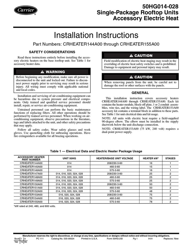
Installation Instructions
Part No: CRECOMZR101A00, CRECOMZR102A00, CRECOMZR103A00,
CRECOMZR104A00, CRECOMZR105A00, CRECOMZR106A00,
CRECOMZR107A00, CRECOMZR108A00
CONTENTS
Page
SAFETY CONSIDERATIONS . . . . . . . . . . . . . . . . . . . 1
GENERAL . . . . . . . . . . . . . . . . . . . . . . . . . . . . . . . . . . . 2
Compliance . . . . . . . . . . . . . . . . . . . . . . . . . . . . . . . . . 2
ECONOMIZER INSTALLATION . . . . . . . . . . . . . . . . . 4
INSTALLING OPTIONAL HH57LW001 SINGLE
OUTSIDE AIR ENTHALPY SENSOR . . . . . . . . . . 10
Enthalpy Control Sensor Configuration . . . . . . . . . 10
• ENTHALPY SETTINGS (ENTHALPY OPTION)
California’s Title 24 High Temperature
Limit Settings . . . . . . . . . . . . . . . . . . . . . . . . . . . . 12
ECONOMIZER SETTINGS . . . . . . . . . . . . . . . . . . . . . 14
Interface Overview . . . . . . . . . . . . . . . . . . . . . . . . . . 14
• ECONOMIZERONE
• POL 224 ECONOMIZER MODULE WIRING
Functions . . . . . . . . . . . . . . . . . . . . . . . . . . . . . . . . . . 15
• FREE COOLING ECONOMIZING
• DEFAULT HYSTERESIS SETTING
• DAMPER MODULATION DURING FREE COOLING
• LOCATION-BASED SHUTOFF SETPOINTS
• COOLING STAGE OPERATION
• MULTI-SPEED FAN SUPPORT
• COOLING DELAY VIA INCREASING FAN SPEED
• DEMAND CONTROLLED VENTILATION (DVC)
• HIGH HUMIDITY LIMITATION
• ANTI-FREEZE PROTECTION
• MAT-BASED ANTI-FREEZE PROTECTION
• OAT-BASED ANTI-FREEZE PROTECTION
• EXHAUST FAN OPERATION
• OCCUPANCY INPUT
• PRE-OCCUPANCY PURGE
• AIRFLOW COMMISSIONING
• FAULT DETECTION AND DIAGNOSTICS
• FIRMWARE UPDATE
MOUNTING, INSTALLATION, AND WIRING . . . . . . 20
Mounting the Economizer Controller Base
Module . . . . . . . . . . . . . . . . . . . . . . . . . . . . . . . . . . 20
Mounting Devices Connected To the Economizer
Controller . . . . . . . . . . . . . . . . . . . . . . . . . . . . . . . . 20
Connecting Peripheral Devices to the Economizer
Controller . . . . . . . . . . . . . . . . . . . . . . . . . . . . . . . . 22
SETUP AND CONFIGURATION . . . . . . . . . . . . . . . . 24
START-UP . . . . . . . . . . . . . . . . . . . . . . . . . . . . . . . . . 29
Cooling with EconomizerONE System . . . . . . . . . . 29
Heating with EconomizerONE System . . . . . . . . . . 29
APPENDIX A — TROUBLESHOOTING . . . . . . . . . . . 30
APPENDIX B — SEQUENCE OF OPERATION . . . . .31
APPENDIX C — MODBUS ADDRESSES . . . . . . . . . .34
SAFETY CONSIDERATIONS
Installation of this accessory can be hazardous due to system
pressures, electrical components, and equipment location (such as
a roof or elevated structure). Only trained, qualified installers and
service technicians should install, start-up, and service this
equipment.
When installing this accessory, observe precautions in the
literature, labels attached to the equipment, and any other safety
precautions that apply:
• Follow all safety codes
• Wear safety glasses and work gloves
• Use care in handling and installing this accessory
It is important to recognize safety information. This is the safety-
alert symbol: . When you see this symbol on the unit and in
instructions or manuals, be alert to the potential for personal
injury.
Understand the signal words DANGER, WARNING, CAUTION,
and NOTE. These words are used with the safety-alert symbol.
DANGER identifies the most serious hazards which will result in
severe personal injury or death. WARNING signifies hazards
which could result in personal injury or death. CAUTION is used
to identify unsafe practices, which may result in minor personal
injury or product and property damage. NOTE is used to highlight
suggestions which will result in enhanced installation, reliability,
or operation.
CAUTION
PERSONAL INJURY HAZARD
Failure to follow this caution may result in personal injury.
Sheet metal parts may have sharp edges or burrs. Use care and
wear appropriate protective clothing, safety glasses and gloves
when handling parts and servicing air conditioning equipment.
CAUTION
PERSONAL INJURY HAZARD
Failure to follow this caution can result in personal injury and
damage to the unit.
Cover the duct opening as a precaution so objects cannot fall
into the return duct opening. Be sure to remove the cover when
installation is complete.
Vertical/Horizontal Low Leak/Ultra Low Leak
EconomizerONE Accessory for
Small Rooftop Units
Select 3 to 12.5 Tons
