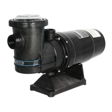
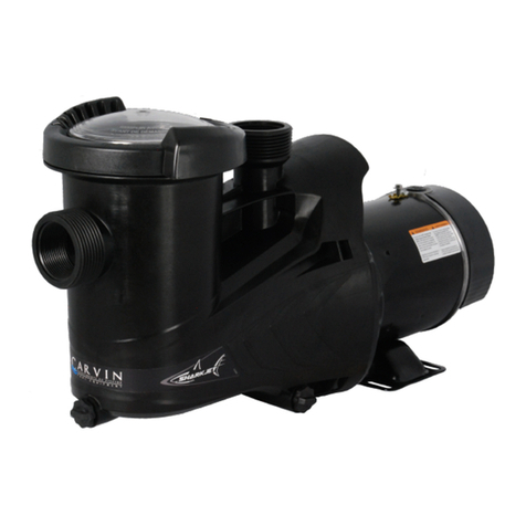
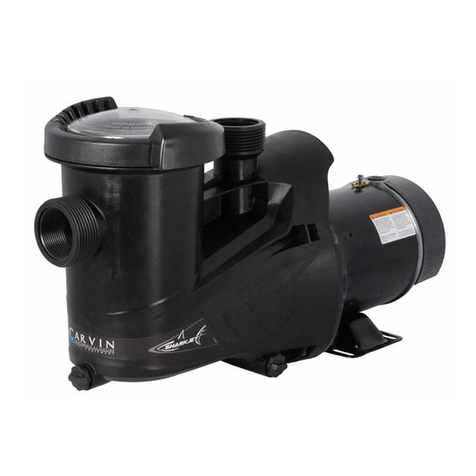
CARVIN SHARK User manual

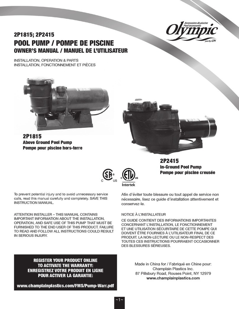
Above Ground Pool Pump Owner’s Manual
Use Only Genuine Replacement Parts
M22904246 WWW.CARVINPOOL.COM
WARNING -READ THIS MANUAL BEFORE INSTALLING AND OPERATING SHARK PUMP. IT INCLUDES IMPORTANT
INFORMATION ABOUT SAFE USE OF THIS PRODUCT.

PLEASE read this manual before installing the pump
Before installation, be sure to read all instructions and warnings carefully. Referto product dataplate(s) for additionnal op
Important Safety Instructions
When installing and using this electricalequipment, basic safety precautions should always be followed , including the followi ng:
M22904246 2MOC.LOOPNIVRAC.WWW
To reduce risk of injury, do not permit
children to use this product unless they
are closely supervised at all times.
WARNING!
(For cord & plug connected units)
Risk of Electric Shock. Connect only to
a grounding type receptacle protected by a ground-fault circuit-inter-
verify that the receptacle is protected by a GFCI.
WARNING!
(For cord & plug connected units) Do
not bury cord.Locate cord to minimize
abuse from lawn mowers, hedge trimmers and other equipment.
WARNING!
(For cord & plug connected units) To
reduce the risk of electric shock, if the
cord is damaged, replace it immediately with the same type of cord
which is available from your local dealer. The new cord must be in-
WARNING!
(For hot tub and spa pumps) Do not
install within an outer enclosure or be-
neath the skirt of the hot tub or spa, unless so marked.
WARNING!
(For cord & plug connected units) To
reduce the risk of electric shock, do not
use an extension cordto connect unit to electric supply;
provide a properly located outlet.
WARNING!
(1.5M) from the pool to prevent it being
used as a means of access to the pool by young children. (See
ANSI/NSPI-8 1996 “Model Barrier Code For Residential Swimming
Pools, Spas and Hot Tubs”).
WARNING!
IMPORTANT:This product has been carefully inspected and packed
at our factory. As the carrier has assumed full responsibility for its
safe arrival, any claim for damage to the shipment, either visible or
concealed, must be made on the carrier.
RISK OF SUCTION ENTRAPMENT HAZARD
WHICH, IF NOT AVOIDED, MAY RESULT IN
SERIOUS INJURY OR DEATH.
Pumps can quickly generate high suction, which poses the risk of
entrapment if improperly connected to suction outlets.
Disembowelment, entrapment, or drowning is possible when body parts
or hair contact damaged, cracked, missing, or unsecured drain covers
and suction outlets.
with the latest NSPI or IAF standards, CPSC guidelines, and national,
state and local codes, to minimize this risk. Some of these requirements
are as follows. Always consult the latest regulations to ensure that your
installation meets the necessary requirements to minimize suction
entrapment.
1.All fully submerged Suction OutletCovers shall be listed to
ANSI/ASME A112.19.8 standard.
2.Do not use apump in an installation where there is only one fully
submerged single suction outlet.
3.If main drains are installed in your pool, there must be a
minimum of twofor each pumping system, and each drain must
include aListedSuction Outlet Cover. Wading pools may have
additional requirements to minimize entrapment hazards.
and must be vented to atmosphere. A skimmer is not considered
a second main drain.
5. When two
rate shall not exceedthe rating of any one of the listed suction
outlet covers installed. When more than two are used, the sum
rate.
6. Each Suction Outlet Cover shall be separated byaminimum
of three feet (3’), measured from center of suction pipes.
7.Avoid installing check valves. If check valves must be used,
ensure that the installation conforms to applicable standards.
8. Never use the pool or spaif a Suction Outlet Coveris damaged,
cracked, missing, or not securely attached. Suction outlet cover
must be attached with stainless steel screws supplied with the
cover. If screws are lost, order replacement parts from your supplier.
NOTE: For the latest NSPI or IAF Standards, contact the Association of
Pool and Spa Professionals (APSP) at www.theapsp.org or
(703) 838-0083, ext. 301. For the latest Consumer Product Safety
Commission (CPSC) Guidelines, contact the CPSC at www.cpsc.gov or
(301) 504-7923. “Guidelines for Entrapment Hazards: Making Pools and
Spas Safer” can be viewed at www.cpsc.gov/cpscpub/pubs
WARNING!

STARTING UP
LUBRICATION
The pump requires no lubrication. Refer tomanufacturer’s recommendations.
CLEANING THE STRAINER BASKET
M22904246 3MOC.LOOPNIVRAC.WWW
CAUTION! Never run the pump without water in
the pump case because lack of water
can damage the shaft seal.
WARNING! During periods when the pump is not in use,
and always during servicing, switch the
ON/OFF switch to OFF and pull the plug from the receptacle.
NOTE: THE PUMP SHALL BE SERVICED BY QUALIFIED PERSONNEL ONLY.
PIPING
The pump has m a l e / f emale sockets to receive 1-1/2" (38mm)
connecting an elbow directly to the pump inlet (use a length of
straight pipe to allow a proper entry of the water). Keep as much of the
suction pipe as possible below the water level of the pool. This will
reduce the priming time but arrange the pipe to rise continuously
toward the pump to prevent high, spots that could form air pockets.
Support the pipes independently so that they do not place strain on
the pump. Install gate valves in the pump suction and pool return
for convenient ser vicing of the equip-
men t. These valves are essential if the equipment is installed below
water level. Keep the gate valve in the suction line fully open during
operation, and make sure that its gland is kept tight to prevent the
entrance of air around the valve stem. Take care during installation to
keep the pipes clean, and make sure that the suction system is absolutely
INSTALLATION
Locate the pump as close to the pool as possible, but keep at a
a means of access to the pool by young children (See previous
Warning). Locate the pump preferably in a dry, shaded, and well-venti-
lated area. Should it be impossible to put the pump at or below
priming, and adds to the press ure developed by the pump. Prepare
a hard, level surface that is large enough to accommodate the associat-
room or pit; Ventilation of t he motor; Access for servicing and winter-
izing the equipment; Protection of the equipment. Make sure the
bearing surface is leveled and straight toreduce vibrations.
This is a self-priming pump, which means that it can raise water to
itself through a dry suction line without using valves, provided the
pump case and strainer body are full of water before the motor is started.
We recommend the use of a swing check valve in the suction pipe, at or
below water level, if the suction lift is more than 5 feet (1.5m) or if the dry
suction line would be more than 10 feet (3.0 m) long. This arrangement
makes the initial priming easy and keep s the suction pipe primed at all
times. The pump is built from glass-reinforced thermoplastic mould-
ings. These eliminate all corrosion problems and insulate the water
passages from the electric motor. A closed impeller, which requires
mple running clearances between impeller and
case promote long life and prevent seizure should sand enter the
pump. The impeller hub forms an insulating sleeve over the motor shaft
and carries the mechanical shaft seal. This seal, which has a pure-car-
bon rotating face working against a ceramic seat, requires no
attention until leakage at the shaft shows that replacement is neces-
sary. For easy routine servicing, the built-in hair and lint strainer
has a transparent cover. For easy access to the working parts, the
removal of four screws allows the motor, bracket, seal, impeller and
for ease of maintenance and repair.
GENERAL
ELECTRICAL CONNECTIONS
Check that the information on the pump nameplate corresponds to
the power supply. Employ a competent electrician to make the wiring
installation in accordance with the local electrical code. Every motor
requires a fused disconnect switch.
For 2-speed pumps,start and prime the pump at HIGH SPEED only. Do
not change to LOW SPEED before the pump is working properly. At HIGH
SPEED (3450 rpm approx.), the motor develops its full horsepower and
the pump generates high capacity and pressure. Use high speed for
maximum
high. At other t imes switch to LOW SPEED (1725 rpm approx.). For
backwashing and vacuuming, HIGH SPEED is required. If the pump
procedure described in the separate instructions for the complete
cases, proceed as follows:
1).Close the gate valves in the suction and return lines. Remove the
cover fr
with water. Replace the cover.
2).Open the gate valves in the suction and return lines and start the
minutes,
fails to work, check for air leaks at the strainer cover, suction line connec-
tions, and valve stem glands before repeating Step 1.
3).
air bubb
line. Locate and correct any leaks immediately.
CONTROLLING THE OUTPUT
Keep the gate valve in the suction line fully open during opera-
tion. Should it be necessary to control the output, use a valve in the
return line.
DRAINING
There are two drain plugs on the pump case. Note that the valves in the
suction and return lines must be open to allow complete draining of
the pump, but that othe r provisions may be necessary for draining
MAINTENANCE
The pump can be serviced without breaking the pipe connections.
Close the ga te valves, SWITCH THE ON/OFF SWITCH TO OFF AND PULL
THE PLUG FROM THE RECEPTACLE before starting work on the pump.
lines. Remove the Strainer Nut and clear cover and lift out the strainer
basket. Clean and replace the basket. Take care to clean o-ring and make
sure that it is well seated underneath clear cover and place cover back on
Re-open valves. Put pump back into operation.
NOTE: Do not re-tighten Strainer Nut while pump is in operation.
MOTOR SPECIFICATIONS

TO DISMANTLE THE PUMP
FREQUENTLY ASKED QUESTIONS
‘’MOTOR DOES NOT START’’
Disconnect switch open; Fuses blown or thermal overload open;
Motor windings burned out; Defective starting switch inside motor;
Disconnected or defective wiring.
‘’MOTOR DOES NOT REACH FULL SPEED’’
Low voltage; Motor windings connected for wrong voltage; Shaft
binding or impeller rubbing.
‘’MOTOR OVERHEATS (Protector trips)’’
Low voltage; Motor windings connected for wrong voltage;
Inadequate ventilation.
‘’PUMP DELIVERS NO WATER’’
Pump not primed; Closed valve in suction or discharge line; Suction
or discharge line plugged; Leakage of air into suction system; Impeller
plugged.
‘’LOW PUMP CAPACITY’’
Check setting of dial valve; Valve in suction or discharge line partly closed;
Suction or discharge line partly plugged; Suction or discharge line too
small; Pump running at reduced speed (see above);
M22904246 WWW.CARVINPOOL.COM 4
Dimensional (Fig.2)
IMPORTANT: BE SURE THE ELECTRICAL POWER IS DISCONNECTED
BEFORE YOU CONTINUE. Refer to illustrated steps on PAGE 5 to guide you.
INSPECTION
Inspect all parts of the pump for wear or damage, and order replacements
as necessary. Check the shaft seal (12) carefully. Look for cracks in the
ceramic seat. Check the seal faces for wear and nicks. Flex the rubber parts
and check them for holes and cracks. Replace the complete seal if any part
is damaged, or if the seal leaks. Do not use old parts.
SHAFT SEAL REPLACEMENT
Take great care while handling the shaft seal (12) to avoid damage to
its carbon and ceramic sealing faces.DO NOT USE OIL OR GREASE ON
THE SEAL PARTS, because either may damage the thermoplastic
material of the pump through overheating
18,65
7,344
23,81
9,375
21,755
55,26
11,350
28,83
21 3/4’’ (55,3 cm)
9 or 12 O’CLOCK
9 3/8’’ (23,8 cm)
9H ou 12H
3’’
(7,62 cm)
7 3/8’’
(18,7 cm)
11 3/8’’
(28,8 cm)
12,38
21,69
8,541
8,046
8’’
(20,3 cm)
8 1/2’’
(21,7 cm)
4 7/8’’
(12,4 cm)
3 1/2’’
(8,9 cm)
Plugged basket in skimmer or hair in lint strainer; Dirty lter; Impeller
plugged.
‘’LOW PUMP PRESSURE’’
Check setting of dial valve; Pump running at reduced speed (see
above); Discharge valve or inlet tting opened too much; Leakage of air
into suction system.
‘’HIGH PUMP PRESSURE’’
Discharge valve or inlet ttings closed too much; Return lines too small;
Dirty lter.
‘’NOISY PUMP AND MOTOR’’
Plugged basket in skimmer or hair in lint strainer; Defective motor
bearings; Valve in suction line partly closed; Suction line partly plugged;
Vacuum cleaner hose plugged or too small; Piping causing strain on
pump case; Impeller rubbing on pump case.
‘’LEAKAGE OF WATER AT SHAFT’’
Shaft seal requires replacement.
‘’AIR BUBBLES AT INLET FITTINGS’’
Leakage of air into suction line at connections; Cover of hair and lint
strainer not airtight; Restriction in suction line; Low water level in pool.
or chemical reaction. Make sure that the pump parts are clean, but be
careful not to scratch the surfaces that come into contact with the seal. .
The ceramic and it’s rubber housing must be installed moistened with
water by pressing them rmly by hand into the motor bracket (13). Make
sure the at surface of the ceramic faces the pump body. Reassemble the
pump retracing the steps illustrated on page 5. Reinstall the pump and run it
for 5 minutes to ensure that no water leaks from the pump case (which
would indicate improper seal installation). If any water is observed leaking
from the pump case, repeat seal installation procedure.
2.TIGHTENING TURN STRAINER NUT
1/4 TURN CLOCKWISE
TO TIGHTEN
STRAINER NUT INSTALLATION (Fig.1)
1.INSERTION
ALIGN MARKERS OF THE
STRAINER NUT AND
BODY AND INSERT.

M22904246 WWW.CARVINPOOL.COM 5
DISMANTLING
USING A 9/16’’ SOCKET, REMOVE
THE FOUR NUTS/BOLTS HOLDING
THE MOTOR TO THE BODY
1. BOLT REMOVAL (Fig. 3)
INSERT A SMALL SCREWDRIVER
BETWEEN THE TWO SNAPS ON THE
MOTOR BRACKET. lIFT GENTLY THE
DIFFUSER’S TAB TO RELEASE.
(REPEAT ON THE OTHER SIDE)
2. DIFFUSER REMOVAL (Fig. 4)
USING A SCREWDRIVER, UNSCREW
THE REAR CAP SCREW TO REMOVE
THE MOTOR’S CAP. USING A SCREWDRIVER TO BLOCK
THE MOTOR SHAFT, UNSCREW THE
IMPELLER BY HAND COUNTER-
CLOCKWISE.
UNSCREW THE FOUR LONG
SCREWS TO REMOVE THE
MOTOR BRACKET
3. MOTOR CAP REMOVAL (Fig. 5) 4. IMPELLER REMOVAL (Fig. 6)
5. MOTORBRACKET REMOVAL (Fig. 7)
6. CERAMIC SEAL REMOVAL (Fig. 8)
USING A FLAT
SCREWDRIVER, PUSH ON
THE CERAMIC FROM THE
BACK OF THE MOTOR-
BRACKET (13)
FLAT SURFACE MUST BE ON
TOP WHEN REASSEMBLING

CARVIN POOL EQUIPMENTINC.
Garantie limitée
Carvin Pool Equipment Inc.("Carvin") warrants “Carvin” pool
products to be free of defects in material and workman-
ship for a period of 24 months fromthe date of purchase
with the following exceptions:
Light Bulbs:Full Moon Watercolor LED light bulbs are
warranted for 12 months from the date of purchase;
incandescent bulbs are warranted for 90 days from the
date of purchase.
Miscellanious:Filter elements, DE grids, white-goods,
tube”, pressure gauges, square rings, o-rings, gaskets,
and all re-placement parts are warranted for 12 months
from the date of purchase.
Chlorine Generation System:Salt Chlorine generation systems
are covered by a limited warranty of 24 months; 100%
date of purchase.
StarLight/StarBright/StarWhite:The LED light is warrantied for a
period of 24 months. The remote control and the AC adapter are
warrantied for 12 months from the date of purchase.
CONDITIONS IN ORDER TO EXERCISE THE WARRANTY
In order to activate this 24 months warranty, ‘’Carvin
products must registered with ‘’Carvin’’ by either of the
following methods:
1- Mail-in Warranty Registration Card
2- Online at, www.carvinpool.com
All defects must be denounced within 72 hours in order to
avoid the spreading to other equipment, failing which; the
present warranty will not be honour ed. This warranty is non
transferable and extends only to the original retail buyer and
only during the time in which the original retail buyer
occupies the site where the product was originally installed.
‘’CARVIN’’ warranty obligation with regard to equipment
which it does no itself manufacture is limited to the warranty
actually extended to ‘’CARVIN’’by its suppliers (i.e. motors).
This warranty applies to products used in swimming pools,
spas, & aquaculture applications only and does not apply to
any product which has been subjected to negligence,
alteration, accident, abuse, misuse, improper installation,
abrasives, corrosion, improper voltage supply, vandalism,
civil disturbances, or acts of God (including but not limited
to damage caused by freezing, lightning strikes, and other
damage caused by catastrophic events). The only warranties
authorized by ‘’CARVIN’’ are those set forth herein. ‘’CARVIN’’
does not authorize other persons to extend any warranties
with respect to its products, nor will ‘’CARVIN’’ assume
liability for any unauthorized warranties made in connection
with the sale of its products. ‘’CARVIN’’ will not be responsi-
ble for any statements that are made or published, written or
oral, which are misleading or inconsistent with the facts as
‘’CARVIN’’.
WARRANTY CLAIM PROCEDURE
Warranty claims shall be made by contacting the
installer/seller, builder, dealer, or retailer (point of purchase)
or the ‘’CARVIN’’ pool products distributor in your area. All
equipment must be inspected by a local ‘’CARVIN’’
authorized representative or at the factory before warranty
is authorized. All charges or expenses for freight to and
from the factory, removal and reinstallation of the products,
or installation of a replacement product are the responsibili-
ty of the purchaser unless otherwise expressly authorized in
writhing by ‘’CARVIN’’. ‘’CARVIN’’, at its discretion, may repair
or replace free of (F.O.B. factory in St-Hyacinthe, Québec,
Canada) any product that proves defective within the
warranty period, or it may issue credit in the amount of the
invoice of the defective equipment in lieu of its repair or
replacement. .‘’CARVIN’’ reserves its right to substitute new
or improved equipment on any replacements.
REV-F
6
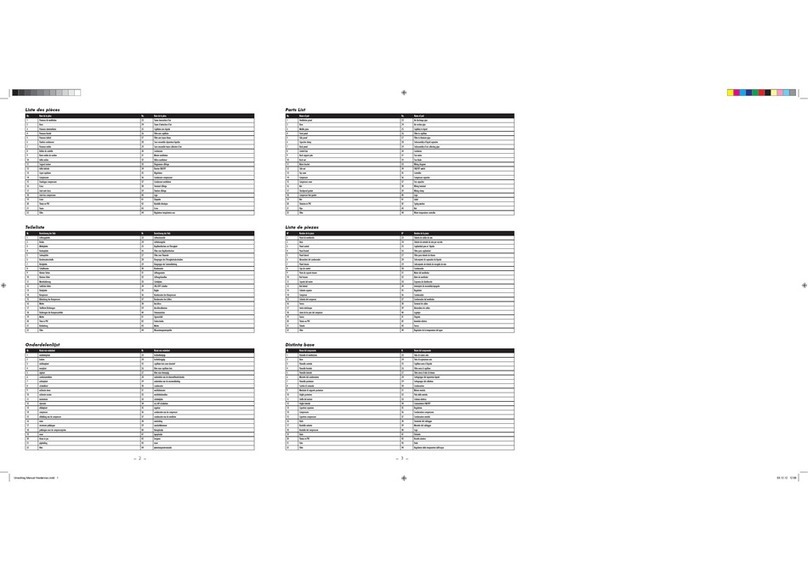
FIG NO. PIÈCE NO. DESCRIPTION
M22904246 WWW.CARVINPOOL.COM
Replacement Parts(Fig. 9)
FIG NO. PIÈCE NO. DESCRIPTION
142-1679-70-RStrainer nut (1/4 turn)
239-0789-03-RStrainer cover
347-0352-41-RStrainer cover O-ring
416-1052-15-RStrainer basket
516-1102-12-RStrainer body 12 O’clock discharge 1-1/2”
6
7
8
9
9
10-1462-07-R
11
5a 16-1102-90-RStrainer body 9O’clock discharge 1-1/2”
10
12
13
14
15
16
17
18
19
20
20A
14-4361-17-R4
47-0225-04-R
31-1587-02-R
31-1609-06-R2 Drain Plug with O-ring ( 2 Per Bag)
47-0361-08-R
05-3760-09-R
05-3759-02-R
05-1234-05-R
05-3853-07-R
02-1347-51-R
23-4857-09-R
23-4856-00-R
47-0214-06-R
06-0517-39-R
10-0802-08-R
22-3403-05-R
Shark Strainer Body Main O-ring
Floating eyeseal
Impeller for 3/4 hp motors
Impeller for 1 hp motors
Impeller for 1.5 hp motors
Impeller for 2 hp motors
Shaft mechanical seal
Motor Bracket US for above ground pool pump
Hex Cap Machine Screw 3/8-16 x 1’’ - StnStl 316 (4 per bag)
Flinger
Motor ( Ask yourlocal poolretailer)
Stainless steel (316) nuts 3/8 - 16 x 21/64Thk . (4 perbag)
9 O’clock connector
9 O’clock connector O-ring
6 Ft. Cord with regular 3 prong plug
3 Ft. Cord with twist lock plug
14-1296-13-R4
-

Bomba Para Piscinas Elevadas Manual Del Usuario
Utilice sólo piezas de repuesto originales
M22904246 WWW.CARVINPOOL.COM
ADVERTENCIA: LEA ESTE MANUAL ANTES DE INSTALAR Y OPERAR LA BOMBA SHARK. INCLUYE
INFORMACIÓN IMPORTANTE SOBRE EL USO SEGURO DE ESTE PRODUCTO.

RIESGO DE APRISIONAMIENTO POR SUC-
CION QUE PUEDE CAUSAR HERIDAS
GRAVES O MORTALES.
La bomba puede crear una fuerte succión rápidamente y generar un riesgo de apri-
puede sufrir desmembramiento, atascamiento o puede ahogarse si una parte de su
Para reducir el riesgo
al máximo, las bombas y las conexiones deben instalarse según a la versión más
reciente de las normas NSPI o IAF, así como también a las directivas de la CPSC y
a los códigos nacionales, provinciales y locales vigentes. A continuación, algunas
de dichas exigencias. Siempre consulte el último reglamento para asegurarse de
que su instalación siga los requerimientos exigidos para reducir al máximo los riesgos
de aprisionamiento por succión.
homologadas por la norma A112.19.8 del ANSI/ASME.
sumergido por completo.
3. Si la piscina posee toma de fondo, habrá que prever dos como mínimo para cada
reducir al máximo los riesgos de aprisionamiento.
para la bomba y deberán instalarse al aire libre. La espumadera o skimmers no se
considera una segunda toma de fondo.
del sistema nunca deberá ser superior a la capacidad nominal de una de las tapas
de succión, la suma de las capacidades nominales deberá ser por lo menos igual
6. Deberá preverse una separación de por lo meno s 0,9m (3 pi) entre cada tapa de
7. No instale válvulas de retención de retención. Si fuesen necesarios,
asegurarse de que su instalación respete las normas exigidas.
atornillarse con tornillos de aceroinoxidable, provistos conla tapa. Si faltan tornillos,
solicite piezas de recambio a su proveedor.
OBSERVACIÓN: Para obtener la versión más reciente de las normas NSPI o IAF,
comuníquese con la Association of Pool and Spa Professionals (APSP) a través del
sitio www.theapsp.org o al número 703-838-0083, interno 301. Para obtener la versión
más reciente de las directivas de la Consumer Product Safety Comisión (CPSC),
comuníquese con dicha comisión a través del sitio www.cpsc.gov
301-504- 7923. Consulta libre del documento “Guidelines for Entrapment Hazards:
Making Pools and Spas Safer” en la dirección www.cpsc.gov/cpscpub/pubs/363.pdf
ATENCIÓN!
POR FAVOR lea este manual antes de instalar la bomba
Antesde la instalación, asegúrese de leerdetenidamente todas las instruccionesyadvertencias.
Instrucciones de seguridad importantes
Durante la instalación y utilización de este artefacto eléctrico, se deberán
observar las medidas de seguridad de base, especialmente las siguientes:
M22904246 2MOC.LOOPNIVRAC.WWW
-
Para reducir los riesgos de heridas, no permita
que los niños utilicen este producto, a excepción de mantenerlos bajo una
estricta y constante vigilancia.
(Para artefactos con enchufe y cable eléctrico).
Riesgo de descarga eléctrica. Únicamente conecte el enchufe a un toma GFCI
el typo de toma.
(Para artefactos con enchufe y cable eléctrico). No
enterrar el cable bajo tierra. Instale el cable eléctrico de manera tal que los daños
que puedan causarle las cortadoras de césped, podadoras y otros equipos sean
mínimos.
(Para artefactos con enchufe y cable eléctrico).
Para reducir los riesgos de descarga eléctrica, reemplace inmediatamente el cable
en caso de encontrarse dañado.
(Para bombas de spa y piscina termal). No
instale el artefacto dentro de un recinto externo ni debajo del spa o piscina termal,
salvo indicación contraria al respecto.
(Para artefactos con enchufe y cable eléctrico).
Para reducir los riesgos de descarga eléctrica, no utilice una extensión eléctrica para
conectar el artefacto al toma corriente; preferentemente instale un toma corriente
en un sitio apropiado.
Instale la bomba por lo menos a 1,50mts. (5 pi)
de la piscina para evitar que los niños la utilicen como acceso a la piscina (consultar
la norma ANSI/NSPI-8 1996 intitulada “Model Barrier Code for Residential
Swimming Pools, Spas and Hot Tubs”).
-
-
-
-
-
-
IMPORTANTE: Este producto ha sido cuidadosamente
inspeccionado y embalado en nuestra fábrica. Dado
que el transportista ha asumido la plena
responsabilidad de su llegada segura, cualquier
reclamación por daño al envío, visible u ocultado,
debe realizarse en el transportista.
ATENCIÓN!
!
ATENCIÓN!
!
ATENCIÓN!
!
ATENCIÓN!
!
ATENCIÓN!
!
ATENCIÓN!
!
ATENCIÓN!
!

LUBRICACIÓN
La bomba no requiere lubricación.
LIMPIEZA DE LA CESTA DE LA BOMBA
M22904246 WWW.CARVINPOOL.COM 3
PRECAUCIÓN
Nunca haga funcionar la bomba sin agua
El caso de la bomba debido a la falta de agua
Puede dañar el sello del eje.
ADVERTENCIA Durante períodos y cuando al servicio de la
bomba no está en uso, poner el interruptor
hasta OFF.
NOTA: LA BOMBA DEBE SER MANTENIDA POR PERSONAL
CUALIFICADO SOLAMENTE.
TUBERÍA
La bomba tiene conectores macho / hembra para recibir conexiones
roscadas de 1-1 / 2 "(38 mm). Mantenga la tubería lo más simple
posible y evite conectar un codo directamente a la entrada de la
bomba (use una longitud de tubo recto para permitir una correcta
entrada del agua). Mantenga tanto como sea posible el tubo de
succión por debajo del nivel de agua de la piscina Esto reducirá el
tiempo de cebado, pero arreglará el tubo para subir continuamente
hacia la bomba para evitar manchas altas que podrían formar bolsas
de aire. Instale válvulas de compuerta en la succión de la bomba y en
las tuberías de retorno de la piscina cerca del sistema de ltro para un
mantenimiento conveniente del equipo. Estas válvulas son esenciales
si el equipo se instala debajo del nivel del agua. Mantenga la válvula
de compuerta en la línea de succión completamente abierta durante
el funcionamiento y asegúrese de que su prensaestopas se mantenga
apretada para evitar la entrada de aire alrededor del vástago de la
válvula. Tenga cuidado durante la instalación para mantener limpias
las tuberías y asegúrese de que el sistema de succión es absoluta-
mente hermético.
INSTALACIÓN
Ubique la bomba lo más cerca posible de la piscina, pero manténgala a
una distancia mínima de 1,5 pies (1,5 pies) como mínimo para que los
niños pequeños no puedan acceder a la piscina (ver Advertencia anteri-
or). Ubique la bomba preferiblemente en un área seca, sombreada y
bien ventilada. En caso de que sea imposible poner la bomba a nivel de
agua o por debajo, elija la posición más baja posible. Esto simplica el
cebado y aumenta la presión desarrollada por la bomba. Prepare una
supercie dura y nivelada que sea lo sucientemente grande como
para acomodar el equipo asociado. Tenga en cuenta lo siguiente:
Drenaje de la sala de ltración o pozo; Ventilación del motor; Acceso
para mantenimiento y acondicionamiento del equipo; Protección del
equipo. Asegúrese de que la supercie de rodamiento esté nivelada y
recta para reducir las vibraciones.
Se trata de una bomba autocebante que permite elevar el agua por sí
misma a través de una tubería de succión seca sin utilizar válvulas,
siempre y cuando el cuerpo de la bomba y el ltro estén llenos de agua
antes de arrancar el motor. Recomendamos el uso de una válvula de
retención en la tubería de succión, a nivel del agua o por debajo, si la
elevación de succión es más de 1,5 m (5 pies) o si la línea de succión
seca tendría más de 10 pies (3,0 m) de largo. Esta disposición facilita el
cebado inicial y mantiene la tubería de succión cebada en todo
momento. La bomba está construida con molduras termoplásticas
reforzadas con vidrio. Éstos eliminan todos los problemas de corrosión
y aíslan los conductos de agua del motor eléctrico. Un impulsor
cerrado, que no requiere ajuste de campo para mantener la eciencia,
se ejecuta dentro de un difusor separado de varias aletas. Unos
espacios de paso entre el impulsor y la carcasa promueven una larga
vida y previenen la convulsión si entra arena en la bomba. El cubo del
impulsor forma un manguito aislante sobre el eje del motor y lleva el
sello mecánico del eje. Este sello, que tiene una cara giratoria de carbón
puro que trabaja contra un asiento cerámico, no requiere atención
hasta que las fugas en el eje muestren que es necesario reemplazarlo.
Para un mantenimiento de rutina fácil, el ltro d e p elo y d e p elusa
incorporado tiene una cubierta transparente. Para un fácil acceso a las
piezas de trabajo, la extracción de cuatro tornillos permite que el
motor, el soporte, el sello, el impulsor y el difusor se retiren como una
unidad. Los conjuntos Shark se simplificaron para facilitar el manten-
imiento y la reparación.
Descripción general
CONEXIONES ELÉCTRICAS
Compruebe que la información en la placa de la bomba corresponde
a la fuente de alimentación. Utilice un electricista competente para
realizar la instalación del cableado de acuerdo con el código eléctrico
local. Cada motor requiere un interruptor de desconexión fundido.
Para bombas de 2 velocidades, arranque y cebe la bomba a ALTA
VELOCIDAD solamente. No cambie a BAJA VELOCIDAD antes de que la
bomba funcione correctamente. A ALTA VELOCIDAD (3450 rpm aprox.),
El motor desarrolla su caballo de fuerza completo y la bomba genera
alta capacidad y presión. Utilice alta velocidad para una ltración
máxima en los períodos pico y siempre que los niveles de turbidez sean
altos. En otras ocasiones, cambie a BAJA VELOCIDAD :1725 rpm aprox.
Lavado a contracorriente y aspiración, se requiere una ALTA
VELOCIDAD. Si la bomba se suministra como parte de un sistema
de ltro completo, siga el procedimiento de arranque descrito en
las instrucciones separadas para todo el sistema de ltro. En otros
casos, proceder como sigue:
1).Cierre las válvulas de compuerta en las líneas de succión y retorno.
Retire la cubierta del cabello y el ltro de la pelusa y llene la bomba
completamente con agua. Vuelva a colocar la cubierta.
2).Abra las válvulas de compuerta en las líneas de aspiración y retorno y
arranque la bomba. Si la bomba no produce un ujo completo de agua
dentro de cuatro o cinco minutos, apague la alimentación y repita el
Paso 1. Si la bomba aún no funciona, compruebe si hay fugas de aire en
la cubierta del ltro, en las conexiones de la línea de succión y en el
vástago de la válvula antes de repetir el Paso 1.
3). Después de unos diez minutos de funcionamiento, compruebe los
accesorios de retorno de la piscina para las burbujas de aire. Un ujo
continuo de aire indica fugas en la línea de succión. Localice y corrija
cualquier fuga inmediatamente.
CONTROLAR LA SALIDA
Mantenga la válvula de compuerta en la tubería de aspiración
totalmente abierta durante la operación. En caso de que sea necesario
para controlar la salida, utilice una válvula en la tubería de retorno.
DRENAJE
Hay dos tapones de drenaje en la caja de la bomba. Nota que las
válvulas situadas en la aspiración y retorno deben estar abiertas para
permitir el drenaje completo de la bomba, el propósito de que otras
disposiciones sean necesarias para el drenaje de las líneas de ltro,
calentador, y tuberías.
MANTENIMIENTO
La bomba puede ser reparada sin romper las conexiones de las
tuberías. Cierre las válvulas de compuerta, el interruptor ON / OFF en
OFF y retire la clavija del receptáculo antes de empezar a trabajar en la
bomba.
Desconecte la alimentación. Cerrar las válvulas en las líneas de
succión y retorno. Retire la tuerca del ltro y despeje la cubierta y
levante la cesta del ltro. Limpie y cambie la cesta. Tenga cuidado de
limpiar la junta tórica y asegúrese de que esté bien asentada debajo
de la cubierta transparente y coloque la cubierta de nuevo en el
cuerpo del colador. Alinee e inserte la tuerca del ltro, sólo a mano
(Fig.1). Vuelva a abrir las válvulas. Vuelva a poner en funcionamiento
la bomba.
NOTA: No vuelva a apretar la tuerca del ltro mientras la bomba esté
en funcionamiento.
ESPECIFICACIONES DEL MOTOR
Para las especicaciones del motor de la bomba. Consulte la etiqueta
del fabricante en el motor.
INICIO LA BOMBA
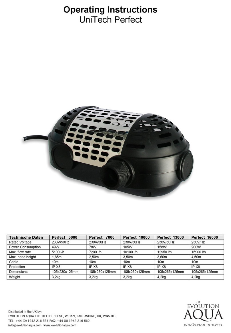
DESMANTELAMIENTO DE LA BOMBA
PREGUNTAS FRECUENTES
'' EL MOTOR
N
O INICIO'': Disyuntor activado o fusibles quemados; recalentamien-
to del arrollamiento del motor; interruptor de encendido defectuoso dentro del
motor o cableado defectuoso.
'' EL MOTOR NO ALCANZA SU MAXIMA POTENCIA'': Baja tensión; eje
bloqueado o fricción de la turbina.
'' RECALENTAMIENTO DEL MOTOR'' (el dispositivo limitador de recalentamiento
no se activa): Baja tensión; ventilación inadecuada.
'' LA BOMBA lA BOMBA SACA POCA AGUA O NINGUNA'' : Bomba no es
imprimado o inltración de aire en el sistema de succión; turbina bloqueada;
válvulade tubo de succión o de retorno parcialmente cerrado; tubo de succión o de
retorno parcialmente obstruido o demasiado pequeño; obstrucción del cesto colador
o del ltro; ltro atascado.
'' BAJA CAPACIDAD DE LA BOMBA ''
Compruebe el ajuste de la válvula selectora; Válvula en la línea de
aspiración o de descarga parcialmente cerrada; Línea de succión o descar-
ga parcialmente taponada; Línea de succión o descarga demasiado
pequeña; Bomba que funciona a velocidad reducida (véase arriba); tapa de
la cesta en el skimmer o el pelo en el ltro de pelusa; Filtro sucio; Impulsor
tapado.
M22904246 WWW.CARVINPOOL.COM 4
Dimensiones (Fig.2)
IMPORTANTE: ASEGÚRESE DE QUE LA ENERGÍA ELÉCTRICA ESTA DESCONECT-
ADA ANTES DE CONTINUAR. Consulte los pasos ilustrados en la PÁGINA 5.
INSPECCIÓN
Inspeccione todas las partes de la bomba para ver si están gastadas o
dañadas y solicite las sustituciones según sea necesario. Compruebe
cuidadosamente el sello del eje (12). Busque grietas en el asiento de cerámi-
ca. Compruebe las caras del sello de desgaste y mellas. Flexión de las piezas
de goma y comprobar que los agujeros y las grietas. Reemplace el sello
completo si alguna pieza está dañada, o si el sello tiene fugas. No utilice
piezas viejas.
REEMPLAZO DE LA JUNTA MECÁNICA
Tenga mucho cuidado al manipular el sello del eje (12) para evitar dañar sus caras de sellado
de carbono y cerámica. NO USE ACEITE O GRASA EN LAS PARTES DEL SELLO, ya que puede
dañar el material termoplástico de la bomba por sobrecalentamiento o reacción química.
Asegúrese de que las partes de la bomba estén limpias, pero tenga cuidado de no rayar las
18,65
7,344
23,81
9,375
21,755
55,26
11,350
28,83
21 3/4’’ (55,3 cm)
9 or 12 O’CLOCK
9 3/8’’ (23,8 cm)
9H ou 12H
3’’
(7,62 cm)
7 3/8’’
(18,7 cm)
11 3/8’’
(28,8 cm)
12,38
21,69
8,541
8,046
8’’
(20,3 cm)
8 1/2’’
(21,7 cm)
4 7/8’’
(12,4 cm)
3 1/2’’
(8,9 cm)
'' BAJA PRESION DE LA BOMBA ''
Compruebe el ajuste de la válvula de marcación; Bomba que funciona a
velocidad reducida (véase arriba); La válvula de descarga o el racor de
entrada se han abierto demasiado; Fuga de aire en el sistema de succión.
'' FUERTE PRESION DE LA BOMBA'' : Válvula de vaciado o empalme de
entrada demasiado cerrados, tubería de retorno demasiado pequeña, ltro
atascado.
'' BOMBA Y MOTOR RUIDOSOS'' : Obstrucción del cesto o del ltro de la
bomba; ; cojinetes del motor defectuosos; válvula del tubo de succión
parcialmente cerrado o tubo parcialmente obstruido; manguera del
succionador obstruida o demasiado pequeña; tubo ejerciendo presión
sobre el chasis de la bomba; fricción de la turbina contra el chasis de la
bomba.
'' FUGA DE AGUA EN EL EJE'' : Remplazar junta del eje.
'' BURBUJAS EN LOS RACORES DE ENTRADA'' :Inltración de aire en el
tubo de succión o en el ltro; restricción en el tubo de succión; bajo nivel de agua en
la piscina.
supercies que entran en contacto con el sello. La cerámica y la carcasa de goma deben
instalarse humedecidas con agua presionándolas rmemente a mano en el soporte del
motor (13). Asegúrese de que la supercie plana de la cerámica esté orientada hacia el
cuerpo de la bomba. Vuelva a montar la bomba siguiendo los pasos ilustrados en la página
5. Reinstale la bomba y colóquela durante 5 minutos para asegurarse de que no haya fugas
de agua de la caja de la bomba (lo que indicaría una instalación incorrecta del sello). Si
observa fugas de agua de la caja de la bomba, repita el procedimiento de instalación del
sello.
2. APRIETE
GIRANDO EL ANILLO
1/4 DE VUELTE EN SENTIDO
HORARIO PARA APRIETE
INSTALACIÓN DEL
ANILLO DE BLOQUEO (Fig.1)
1. INSERCIÓN
ALINEAR LAS MARCAS
PARADAS Y INSERT.

M22904246 WWW.CARVINPOOL.COM 5
DESMONTAJE
USANDO UN ZÓCALO DE 9/16 '',
QUITE LAS CUATRO NUECES /
PERNOS QUE SOSTENEN EL
MOTOR AL CUERPO.
1. DESMONTAJE DEL TORNILLO (Fig. 3)
INSERTE UN PEQUEÑO DESTORNILLA-
DOR ENTRE LOS DOS CHASQUIDO EN
EL SOPORTE DEL MOTOR. LEVANTE
LENTAMENTE LA LENGUA DEL
DIFUSOR PARA LIBERARLA. (REPITA
EN OTRO LADO)
2. DESMONTAJE DEL DIFUSOR (Fig. 4)
UTILIZANDO UN DESTORNILLADOR,
DESATORNILLE EL TORNILLO
TRASERO PARA RETIRAR EL TAPÓN
DEL MOTOR. USANDO UN DESTORNILLADOR
PARA BLOQUEAR EL EJE DEL
MOTOR, DESENROSCAR LA
TURBINA EN SENTIDO
ANTIHORARIO.
DESTORNILLAR LOS CUATRO
TORNILLOS LARGOS PARA
RETIRAR EL SOPORTE DEL
MOTOR
3. DESMONTAJE DEL CAPO DEL MOTOR (Fig. 5) 4. EXTRACCIÓN
DE LA TURBINA
(Fig. 6)
5. DESMONTAJE DEL
SOPORTE DEL MOTOR (Fig. 7)
6. CERAMICA EXTIRPATIÓN (Fig. 8)
USANDO UN DESTORNILLADOR
PLATO, EMPUJE LA CERÁMICA
DE LA PARTE POSTERIOR DEL
MOTORBRACKET (13)
LA SUPERFICIE PLANA DEBE
ESTAR EN LA CIMA.

REV-F
6
FIGNO. PIÈCE NO. DESCRIPTION
M22904246 WWW.CARVINPOOL.COM
PIEZAS DE REPUESTO(Fig. 9)
FIG NO. PIÈCE NO. DESCRIPTION
142-1679-70-RAnillode Bloqueo (cuarto de vuelta)
239-0789-03-RTapa
347-0352-41-RJunta tórica deTapa
416-1052-15-RCesta de la Bomba
516-1102-12-RCuerpo Principal descarga vertical 1-1/2”
6
7
8
9
9
10-1462-07-R
11
5a 16-1102-90-RCuerpo Principal descarga horizontal 1-1/2”
10
12
13
14
15
16
17
18
19
20
20A
14-4361-17-R4
47-0225-04-R
31-1587-02-R
OPTIÓN DESCARGA HORIZONTAL
31-1609-06-R2 Tapones de Drenaje ( 2 Por Bolsa)
47-0361-08-R
05-3760-09-R
05-3759-02-R
05-1234-05-R
05-3853-07-R
02-1347-51-R
23-4857-09-R
23-4856-00-R
47-0214-06-R
06-0517-39-R
10-0802-08-R
22-3403-05-R
Junta tórica del cuerpo Principal SHARK
Junta tórica del Difusor
Shark Difusor
Sello de ojo Flotante
Turbina 3/4 hp motor
Turbina 1 hp motor
Turbina 1.5 hp motor
Turbina 2 hp motor
Junta Mecánica
Soporte del Motor
Tornillos cabeza hexagonal de acero inoxidable 3/8-16 x 1’’ (4 Por Bolsa)
Junta Lanzador
Motor (Pregúntele asudistribuidor local de piscinas)
Tuercas Acero inoxidable 3/8 - 16 x 21/64 grueso. (4 por Bolsa)
Conector para descarga horizontal
Junta de conector para descarga horizontal
Cable eléctrico (6 pies) con enchufe regular de 3 clavijas
Cable eléctrico (3 pies) con enchufe turn-lock
14-1296-13-R4
-
Garantía limitada
garantiza que los productos para piscinas “ ”
están exentos de todo defecto de fabricación y de mano de
obra durante un período de 24 meses a partir de la fecha de
compra. Las excepciones siguientes se aplican:
Bombillas de luz: las bombillas de luz FullMoon Watercolor
LED tienen garantía por doce meses desde la fecha de
compra; las bombillas de luz incandescentes están
garantizadas por 90 días desde la fecha de compra.
Varios: Accesorios para el filtro, mallas DE, línea blanca,
cestos para el filtro, solapas y tubos lisos para cestos del
filtro, manómetros, anillos cuadrados, arandelas, juntas y
todas las partes de repuesto están garantizados por doce
meses desde la fecha de la compra.
CONDICIONES PARA PODER EJECUTAR
LA GARANTÍA:
Para poder activar esta garantía de 12 meses, los productos
“ ” deben estar registrados con “ ” ya
sea por cualquiera de los siguientes métodos:
Por correo: envíe por correo la Tarjeta de Registro de
garantía
En línea: en
Todos los defectos deben ser reportados dentro de 72 horas
para poder evitar la extensión del defecto a otros equipos, si
no se cumple con esto la presente garantía no será aceptada.
Esta garantía no es transferible y se extiende sólo al
comprador minorista original y dura solamente el tiempo
durante el cual el comprador minorista original ocupe el lugar
donde se instaló en un primer momento el producto.
La responsabilidad de garantía de “ ” respecto a
equipos fabricados por terceros se limita a la garantía
expedida a “ ” por parte de sus proveedores
(por ejemplo: motores).
Esta garantía se aplica a productos utilizados en piscinas,
spas y productos de acuicultura solamente y no se ap lica a
ningún producto que haya sufrido daños, cambios,
accidentes, abusos, mal uso, instalación inadecuada,
abrasivos, corrosión, voltaje inadecuado, vandalismo,
alteraciones, casos de fuerza mayor (que incluyen daños
causados por heladas, relámpagos y catástrofes). Las únicas
garantías autorizadas por “ ” son las que se
detallan en este documento. “ ” no autoriza a que
otras personas - extiendan la garan tía de sus productos, ni
tampoco asumirá ninguna responsabilidad por garantías no
autorizadas, realizadas en relación con la venta de sus
productos. “ ” no se hará responsable de ninguna
declaración hecha o publicada, escrita o verbal, que sea
errónea o inconsistente con los hechos publicados en los
textos y especificaciones de “ ”.
PROCEDIMIENTO DE RECLAMO DE GARANTÍA
Los reclamos de garantía deben realizarse contactando al
instalador/vendedor, constructor, distribuidor, representante
(punto de venta), o bien al distribuidor de productos para
piscinas “ ” que corresponda a su zona de
residencia. Antes de que se autorice la garantía, todos los
equipos deben ser revisados o bien en fábrica, o bien por un
representante local de “ ”. Todos los gastos de
flete hacia y desde la fábrica, el retiro y la reinstalaciónde los
productos o la instalación del repuesto son responsabilidad
del comprador salvo que “ ” autorice
expresamente lo contrario. “ ”, sin dejarlo
expreso, puede reparar o reemplazar sin cargo (precio de
fábrica F.O.B. en )cualquier
producto que tenga fallas dentro del período de garantía o
puede emitir un crédito por la cantidad facturada por el
equipo con fallas en lugar de su reparación o reemplaz o.
“ ” se reserva el
derech
o de sustituir equipo nuevo o
mejorado en cualquier reemplazo.
CARVIN POOL EQUIPMENT INC.
CARVIN POOL EQUIPMENT INC. (”Carvin pool”)
Carvin Pool
Carvin PoolCarvin Pool
www.carvinpool.com
Carvin Pool
Carvin Pool
Carvin Pool
Carvin Pool
Carvin Pool
Carvin Pool
Carvin Pool
Carvin Pool
Carvin Pool
Carvin Pool
Carvin Pool
St-Hyacinthe, Qc, Canada
Table of contents
Languages:
Other CARVIN Swimming Pool Pump manuals