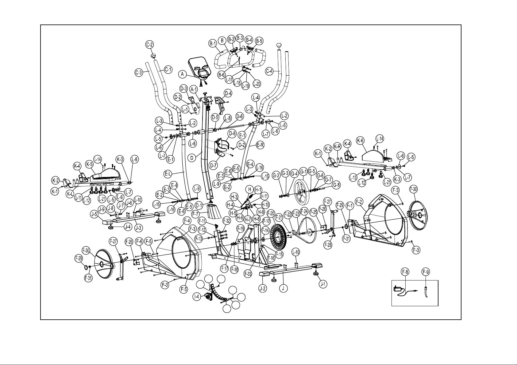
Casall XT100 User manual

USER MANUAL
Casall XT100
93018

Important: Please locate your serial number and record in the box below for service support
purposes.
Serial number here:
Serial number

L-13: Spring washer Ø6 (8)
L-11: Sleeve Ø7xØ12x30L L-21 Flat washer
L-5: Hex bolt
M8*P1.0*30L(4)
93018/XT100
L-12: Knob (foot pedal)M6xP1.0 (8)
L-6: Gasket (4)
L-7: Flat washer Ø8.5xØ25x2t (4)
Ø6xØ13x1t (4)
L-8: Semicircle washer
Ø17.5xØ25x0.3t (4)
L-4: Semicircle washer
Ø8xØ19x2t (4)
93018/XT100
L-17” Metal cover (1) L-19: Spring washer Ø7x2t (2)
L-18 Flat washer Ø7xØ12x1t (2)
L-20: Fixing bolt M7xP1.0x30L (2)
L-15 Allen bolt M8xP1.25x55L (2)
L-14: Carriage bolt M6xP1.0x50L (8)
Box spanner (1)
Allen key (2)
L-9: Lock nut for 3/8'' (2)
L-2: Carriage bolt M8xP1.25x40L (4)
L-3: Acorn nut (4)
L-10: Allen bolt M8xP1.25x16L (8)
L-16: Flat washer Ø8xØ16x1t (2)
L-1: Screw M3x25L (1)

I-1 I-2
I-3
I
I-6
I-7
I-5

Parts List
Number Description Q'ty
A, A-1 Console & screw 1 SET
B Front handlebar 1 PCS
B-1 Foam grip for front handlebar 2 PCS
B-2 Hand pulse 2 PCS
B-3 Cap for Front handlebar 2 PCS
B-4 Screw M4x20L 2 PCS
B-5 Semicircle washer 1.5t 2 PCS
B-6 Wire for hand pulse 1 PCS
C-1 Upper handlebar (Left) 1 PCS
C-2 Cap for upper handlebar 2 PCS
C-3 Foam grip for upper handlebar 2 PCS
C-4 Upper handlebar (Right) 1 PCS
D Handlebar post 1 PCS
D-1 Upper console cable 1 PCS
D-2 Screw M5xP0.8x12L 4 PCS
D-3 Left cover for console 1 PCS
D-4 Right cover for console 1 PCS
D-5 Bushing for handlebar post 2 PCS
D-6 Axle for handlebar post 1 PCS
D-7 Bottle holder seat 1 PCS
D-8 Bottle holder 1 PCS
E-L Lower handlebar (Left) 1 PCS
E-R Lower handlebar (Right) 1 PCS
E-1 Bushing for Lower handlebar 4 PCS
E-2 C-type φ12 4 PCS
E-3 Flat washer φ12xφ19x1t 4 PCS
E-4 Bushing for Lower handlebar 4 PCS
E-5 Bushing 2 PCS
E-6 Wave washer φ12.5xφ18x0.3t 4 PCS
F-1 Front cover (Right) for main front 1 PCS
F-2 Right chain cover 1 PCS
F-3 Screw M5x16L 8 PCS
F-4 Left chain cover 1 PCS
F-5 Screw M4x50L 7 PCS
F-6 Front cover (Left) for main front 1 PCS
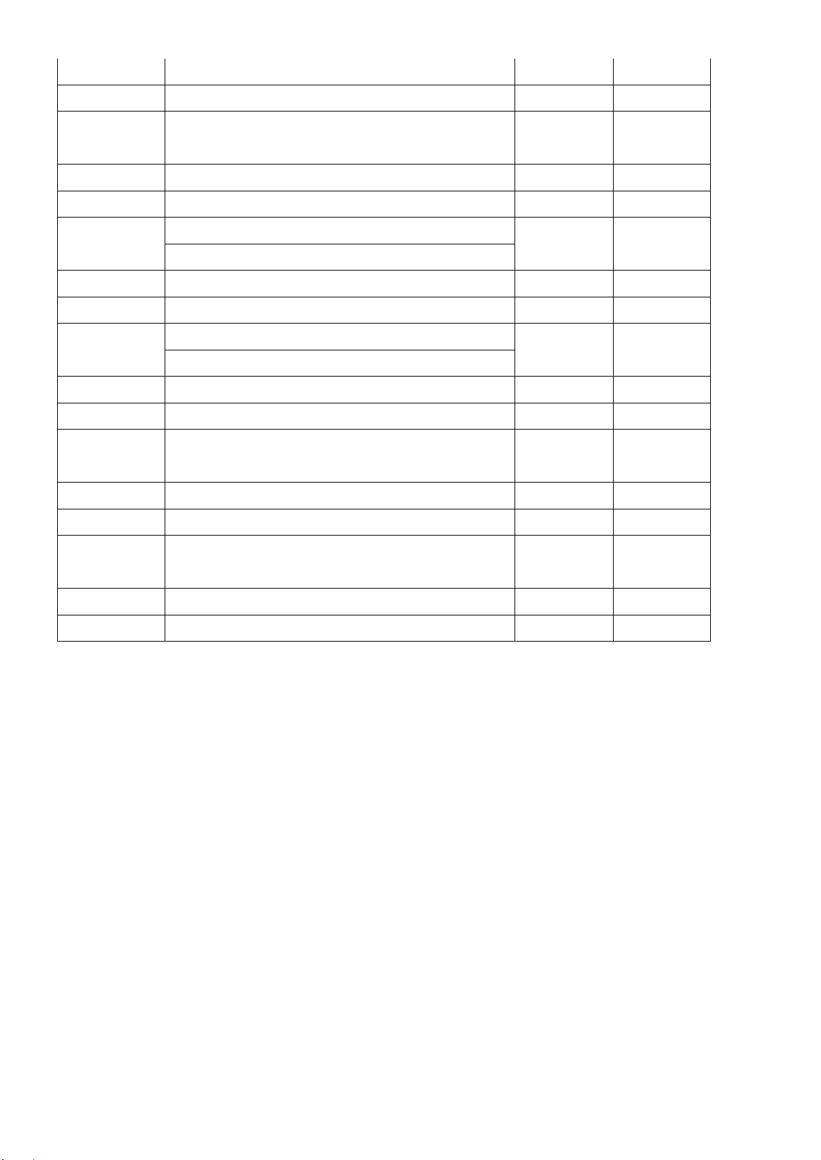
F-7 Cover for handlebar post 1 PCS
F-8 Adaptor 1 PCS

F-9 DC cable 1 PCS
F-10 Main frame 1 PCS
F-12 Flat washer φ8xφ19x2t 4 PCS
F-13 Allen bolt M8xP1.25x16L 4 PCS
F-14 Bearing 2 PCS
F-15 Sensor box
1
PCS
F-16 Screw M4x12L 1 PCS
F-17 C-type φ20 1 PCS
F-18 Wave washer φ20xφ30x0.3t 1 PCS
F-19 Flat washer φ20.3xφ30x1t 1 PCS
F-20 Belt pulley 1 PCS
F-21 Hex. screw M8xP1.25x12Lx5t 3 PCS
F-22 Belt 1 PCS
F-23 Bushing 1 PCS
F-24 Shaft 1 PCS
F-25 Screw M4x12L 10 PCS
F-26 Inside cover for disc 2 PCS
F-27 Cross disc 2 PCS
F-28
Flat washer
φ
5xφ16x1t
4 PCS
F-29 Cap for Round disc 2 PCS
F-30 Round disc 2 PCS
F-31 Pattern nut
2
PCS
F-32 Spring washer φ8.1*φ12.9*2.4T
4
PCS
F-33 Sensor holder
1
PCS
G-1~G-8 Flywheel set 1 SET
H Idler lever 1 PCS
H-1 Spring
1
PCS
H-3 Hex. screw M6xP1.0x100L
1
PCS
H-4 Hex. screw M6xP1.0x12L
1
PCS
H-5 Flat washer φ6xφ13x1t
1
PCS
H-6 Flat washer φ10xφ14x1t
1
PCS
H-7 Idler wheel
1
PCS
H-8 Wave washer φ10.5xφ15x0.3t
2
PCS
H-9 Flat washer φ8.5xφ25x2t
1
PCS
H-10 Nylon nut M8
1
PCS
H-11 Hex. screw M8xP1.25x18L
1
PCS
I Magnetic set
1
PCS
I-1 Hex. Screw M6xP1.0x16L
2
SET
I-2 Flat washer φ6xφ13x1t
2
PCS

I-3 Spring washer φ6
2
PCS
I-4, F-11 Gear box w/cable
1
SET
I-7 Hex. nut M6
1
PCS
J Rear stabilizer
1
SET
J-1 Adjustment pad for rear stabilizer 2 PCS
J-2 End cap for rear stabilizer
2
PCS
J-3 Front stabilizer
1
SET
J-4 Adjustment pad for front stabilizer 2 PCS
J-5 End cap for front stabilizer
2
PCS
J-6 Nylon nut M8 2 PCS
J-7 Flat washer φ8xφ16x1t 2 PCS
J-8 Transport wheel 2 PCS
J-9 Screw M8xP1.25x40L 2 PCS
K-L Left pedal arm 1 PCS
K-R Right pedal arm
1
PCS
K-1 Screw M5xP0.8x12L
4
PCS
K-2 Front cover (Left) for pedal arm
2
PCS
K-3 Bushing
4
PCS
K-4 Front cover (Right) for pedal arm
2
PCS
K-5 Left pedal
1
PCS
K-6 Right pedal 1 PCS
L-1~L-21 Hardware pack 1 SET

Assembly Stage #1
1. Attach the front stabilizer (J-3) to the main frame (F-10) using four Allen bolts (L-10).
2. Attach the rear stabilizer (J) to the main frame (F-10) using four Allen bolts (L-10).
3. Please remove the handlebar post cover (F-7) from the main frame (F-10).
After the assembly, the machine can be adjusted to a slightly uneven ground by adjusting the
height of the foot caps at the front and back. The pre-assembled transportation wheels in the
front allow moving the Elliptical easily and therefore need to be pointing down at the front (45°)
during assembly.
Assembly Stage #2
1. Take the wave washer (L-8) and pass it through the cross disc (F-27).
2. Assemble the R/L pedal arms (K-L, K-R) to the cross disc (F-27) by adding a flat washer (L-
7), a gasket (L-6), and an Allen bolt (L-5).
x2
x2
Ø8xØ25x2
M8x30L
L-6
L-8
L-5
L-7
2
x2
x2
Ø17.5xØ25x0.3t
M8xP1.25x16L
x8 L-10
1

Assembly Stage #3
1. Put the R/L pedal (K-5, K-6) onto the pedal arm (K-L/R) and tighten it using a knob (L-12), flat
washers (L-21), spring washers (L-13), sleeves (L-11) and carriage screws (L-14) on each
side.
Please keep in mind, the left and right pedals need to be placed in identical positions.
Assembly Stage #4
1.Please remove the four sets of Allen bolts (F-13) and flat washers (F-12) and spring washer
(F-32) from the main frame (F).
2.Take the handlebar post (D) and pass it through the handlebar post cover (F-7).
3. Hold the handlebar post (D) and connect the lower console cable (F-11) and the upper
console cable (D-1).
4.Slide the handlebar post (D) into the main frame, then fix it with four sets of Allen bolts (F-13)
and flat washers (F-12) and spring washer (F-33).
Ø6x1.5T
x8
x4
Ø7xØ12x30L
L-11
L-13
M6xP1.0x50L
x8 L-14 3
L-11 L-12
L-12L-13
L-14
L-21
L-21
M6xP1.0
x8
Ø6xØ13x1t
x4 L-21
L-12
K-L
K-R
M8xP1.25x16L
x4
Ø8xØ19x2t
x44
F-12
F-13

Assembly Stage #5
1. Take the axle (D-6) and pass it through the handlebar post (D).
2. Pass the axle through the wave washer (L-8) and the lower handlebar (E-R/L), then fix with
the flat washers (L-7), gaskets (L-6) and Allen bolts (L-5) on each side.
3. Tighten the Allen bolt (L-15) with flat washers (L-16) and nylon nuts (L-9) to connect the
pedal arms (K-L/R) and lower handlebars (E-R/L) on each side.
Please note: Use two Allen key tools to fix the bolts (L-5) on both sides at the same time.
x2
M8x30L
Ø17.5xØ25x0.3t
Ø8xØ16x1t
M8xP1.25x55L
L-6
L-8
L-5
L-7
L-16
L-15
Ø8xØ25x2t
5
K-L
K-R
E-L
E-R
x2
x2
x2
x2
x2

Assembly Stage #6
1. Please remove the four sets of screws (K-1) from the pedal arms (K-L/R).
2. Assemble the front cover L/R (K-2, K-4) to the pedal arms (K-L/R) by adding screws (K-1) on each
side.
3. Pass the hand-pulse wire (B-6) through the handlebar post (D) hole.
4. Attach the front handlebar (B) to the handlebar post (D) using the clamp cover (L-17), then
fix it with two flat washers (L-17), two spring washers (L-19) and two fixing bolts (L-20).
6
L-18
L-17 L-19 L-20
Ø7xØ12x1t
Ø7x2T
x1 L-17
L-18
L-19
M7xP1.0x30L
x2 L-20
x2
x2

Assembly Stage #7
1. Connect the computer cables (D-1) and hand pulse wire (B-6)to the computer, then attach the
computer (A) to the computer bracket with the enclosed screws (A-1).
2. Please remove the screw (D-2) from the handlebar post (D).
3. Assemble the console holder cover (D-3, D-4) for the handlebar post (D) by adding the screw
(D-2) and self-tapping screw (L-1).
7

Assembly Stage #8
1. Attach the R/L upper handlebar (C-1, C-4) to the lower handlebar (E-R/L) by adding the
carriage bolts (L-2), nuts (L-3) and semicircle washers (L-4).
2. Remove the pre-installed Screws (D-2) on the handlebar post first, and then assemble the
Bottle holder (D-8) using Screw (D-2).
3. Connect the adaptor (F-8) to the DC hole (located on the back of the chain cover).
Ø8xØ19x2t
M8xP1.25x40L
Ø17.5xØ25x0.3t
x4L-3
L-2
L-4
8
x4
x4

SM1790-67 SERIES INSTRUCTION MANUAL
DISPLAY FUNCTIONS
ITEM
DESCRIPTION
TIME Count up – No preset target. Time will count up from 00:00 to maximum
99:59 with each increment being 1 minute.
Count down –
If training with preset Time, Time will count down from reset
to 00:00.
Each preset increment or decrement is 1 minute between 00:00 to 99:00.
SPEED
Displays current training speed. Maximum speed is 99.9 KM/H or ML/H.
DISTANCE Accumulates total distance from 0.00 up to 99.9 KM or ML. The user may
preset target distance data by using UP/DOWN button. Each increment or
decrement is 0.1KM or ML between 0.00~99.9.
CALORIES Accumulates calories consumption during training from 0 to maximum
9999 calories.
(This data is a rough guide for comparison of different exercise sessions
which cannot be used in medical treatment.)
PULSE
User may set up target pulse from 0 – 30 to 230; computer buzzer
will beep when the actual heart rate is over the target value during the
workout.
RPM
Displays the Rotation Per Minute. Display range 0~999
WATTS Workout power consumption
Range 0 ~ 999
In Watt constant mode, computer will remain preset watt value (setting
range 0~350)

MANUAL
Manual mode workout.
PROGRAM
12 PROGRAM selection.
USER
PROGRAM
User creates resistance level profile.
H.R.C.
Target HR training mode.
WATT
PROGRAM
WATT constant training mode.
KEY FUNCTION
PS. Because of different console designs not all consoles have the total reset function key.
Training Data
The computer calculates and displays all values automatically according to the user’s exercise
status.
(see table).
Take note:
* If only a “P” is shown instead of pulse value, it is impossible to measure the HR. Keep both
hands holding on the handlebar properly so that computer can detect your heart rate.
ITEM DESCRIPTION
Up
(Encoder)
Increase resistance level
Setting selection.
Down
(Encoder)
Decrease resistance level
Setting selection.
Mode / Enter
Confirm setting or selection.
Reset
Press and hold for 2 seconds, the computer will reboot and start from user
setting.
Go back to the main menu during the presetting of your workout value or stop
mode.
Start/ Stop Start or Stop workout.
Recovery Test heart rate recovery status.
Total Reset Power on again and resume all preset values.

* The profile displayed in the center field depends on the type of exercise that has been set.
The computer provides a number of ways to vary the exercise session and make it more
motivating.
The following exercising are available:
-Manual Training (training without programs)
-Training with Programs (there are 12 programs preset, P01~P12)
-Training with the Heart Rate program (H.R.C)
-Training with USER program (set your own desired profile)
-Training with WATT program (Power consumption)
OPERATION:
POWER ON
Plug in the power supply, the computer will power on and display all segments on LCD for 2
seconds (Drawing 1).
Drawing 1
WORKOUT SELECTION
Use UP or DOWN (Encoder) to select to workout manually (Drawing2)Program (Drawing 3)
User Program (Drawing 4)H.R.C. (Drawing 5) Watt(Drawing 6).
Drawing 2Drawing 3
Hand sensor for
pluse measurement

Drawing 4Drawing 5
Drawing 6
Manual Mode
Press START in main menu to start workout in manual mode.
1. Use UP or DOWN (Encoder) to select workout program, choose MANUAL and press MODE
/ ENTER to get into.
2. Use UP or DOWN (Encoder) to preset TIME (Drawing 7), DISTANCE (Drawing 8),
CALORIES (Drawing 9), PULSE (Drawing 10) and press MODE / ENTER to confirm.
3. Press START/STOP to start workout. Use UP or DOWN (Encoder) to adjust the load level. If
the load level display in WATT window is not adjusted for more than 3s, it will switch to
display WATT (Drawing 11).
4. Press START/STOP to pause your workout. Press RESET to go back to the main menu.
Drawing 7Drawing 8
Drawing 9Drawing 10
Drawing 11
Program Mode
1. Use UP or DOWN (Encoder) to select your workout program, choose Beginner mode and
press MODE / ENTER to get into.
2. Use UP or DOWN (Encoder) to select program 1~12 (Drawing 12) and press MODE /
ENTER to get into.
3. Use UP or DOWN (Encoder) to preset TIME.
4. Press START/STOP to start the workout. Use UP or DOWN (Encoder) to adjust the load
level.
5. Press START/STOP to pause the workout. Press RESET to go back to the main menu.

Drawing 12
User Program Mode
1. Use UP or DOWN (Encoder) to select your workout program, choose User Program mode
and press MODE / ENTER to get into.
2. Use UP or DOWN (Encoder) to create a user profile (Drawing 13). There are a total of 20
columns, the user can adjust each column’s load level. The user can hold MODE / ENTER 2
seconds to quit during setting.
3. Use UP or DOWN (Encoder) to set TIME.
4. Press START/STOP to start the workout. Use UP or DOWN (Encoder) to adjust the load
level.
5. Press START/STOP to pause the workout. Press RESET to go back to the main menu.
Drawing 13
H.R.C. Mode
1. Use UP or DOWN (Encoder) to select your workout program, choose H.R.C. and press
MODE / ENTER to get in.
2. Use UP or DOWN (Encoder) to set your age (Drawing 14).
3. Use UP or DOWN (Encoder) to select 55%.75%.90% or TAG (TARGET H.R.) (default : 100,
Drawing 15).
4. Use UP or DOWN (Encoder) to preset your workout TIME.
5. Press START/STOP to start or stop the workout. Press RESET to go back to the main menu.
Drawing 14 Drawing 15
Watt Mode
1. Use UP or DOWN (Encoder) to select your workout program, choose WATT and press
MODE / ENTER to get in.
2. Use UP or DOWN (Encoder) to preset WATT target. (default: 120, Drawing 16)
3. Use UP or DOWN (Encoder) to preset TIME.
4. Press START/STOP to start the workout. Use UP or DOWN (Encoder) to adjust the Watt
level.
5. Press START/STOP to pause the workout. Press RESET to go back to the main menu.

Drawing 16
Measuring your pulse with the hand sensors
The hand sensors are not medical products, but rather exercising tools designed for the
approximate measurement and display of the pulse rate when exercising with the crosstrainer.
RECOVERY
After exercising for a period, keep holding on the hand grips and press the RECOVERY key.
The display will stop showing any functions except for “TIME”. Time starts counting down from
00:60 to 00:00 (Drawing 17). The screen will display your heart rate recovery status with F1,
F2…. to F6. F1 is the best, F6 is the worst (Drawing 18). The user may keep exercising to
improve the heart rate recovery status. (Press the RECOVERY button again to return to the
main display.)
Drawing 17 Drawing 18
Noted:
1. After 4 minutes without pedaling or pulse input, the console will enter into power saving mode.
Press any key to wake the console up.
2. When the computer acts abnormally, please unplug the adaptor and plug in again.
Attention! All preset data will be lost when unplugging the power (adaptor) from the
"machine".
You can measure your pulse with the two-
hand sensor on the handle.
>> Place both hands on the hand sensor on
the handle while you exercise and wait
briefly for the pulse to be displayed.
Hand sensor for
pluse measurement
This manual suits for next models
1
Table of contents
Other Casall Elliptical Trainer manuals