Casall INFINITY 1.2X User manual

1
Casall INFINITY 1.2X
CROSSTRAINER
93008

2
Important: Please locate your serial number and record in the box below for service
support purposes.
Serial number here:

3
S
c
r
e
w
M
3
*
1
4
L
(
2
)
a
l
l
e
n
b
o
l
t
M
8
*
3
0
L
(
2
)
C
u
r
v
e
w
a
s
h
e
r
1
7
.
5
*
2
5
*
0
.
3
T
(
2
)
F
l
a
t
W
a
s
h
e
r
1
6
f
o
r
M
8
b
o
l
t
(
4
)
A
l
l
e
n
B
o
l
t
(
m
o
v
a
b
l
e
h
a
n
d
l
e
b
a
r
)
M
8
*
5
5
(
2
)
S
c
r
e
w
M
3
*
2
5
L
(
8
)
a
l
l
e
n
b
o
l
t
M
8
*
1
2
L
(
8
)
Allen Bolt M7*P1.0*30L(2)
P-1
Regular Washer
7*1t(2)
P-2
Metal cover (1)
P-3
Spring Washer
7*2t(2)
P-4
P-5
P-6
P-8
P-10
s
t
e
e
l
w
a
s
h
e
r
(
2
)
P-11
F
l
a
t
w
a
s
h
e
r
8
*
2
5
*
2
T
(
2
)
P-12P-13
P
-
1
5P
-
1
4
a
l
l
e
n
b
o
l
t
M
8
*
1
6
L
(
4
)
P-7
A
c
o
r
n
N
u
t
f
o
r
M
8
B
o
l
t
(
2
)
P-9
INFINITY 1.2X

4
Knob (foot pedal)M6*P1.0 (4)
Spring Washer for handlebar bolt 6(black)(4) Carrage bolt M6*P1.0*40L (black)(4)
P-16
P
i
v
o
t
T
u
b
e
(
4
)
P-18
P-17 P-19
A
l
l
e
n
K
e
y
(
2
)
B
o
x
S
p
a
n
n
e
r
(
1
)
INFINITY 1.2X

5
Assembly Diagram
K-1

6
EXPLODED DIAGRAM
H-8

7
PARTS LIST
No. Item spec. Q'ty
A , A-1 Computer & Screw for computer 1SET
B-1 Front handlebar 1PC
B-2 Foam grip for front handlebar 2PCS
B-3 End cap for foam grip φ7/8" 2PCS
B-4 Hand pulse WP1007-33B 1SET
B-5 Screw M3x20L 2 PCS
B-6 Wire for hand pulse 1 PC
C-1 Upper handlebar ( L) 1SET
C-2 End cap for upper handlebar (R&L) φ1 1/4" 2PCS
C-3 Foam grip for upper handlebar 2PCS
C-4 Upper handlebar ( R) 1PC
D-1 Handlebar post 1PC
D-2 Upper computer cable 1PC
D-3 Screw for computer cover M5x14L 2PCS
D-4 Bushing 2PCS
D-5 Allen bolt M8x16 4PCS
D-6 Flat washer φ12xφ19x1t 4PCS
D-7 Screw for bottle holder M5x20L 4PCS
E-1~E7 First-lower handlebar (R& L) 1SET
F-1 Main frame 1SET
F-2 C-type ring φ12 1PC
F-3 Wave washer φ20xφ30x0.3t 1PC
F-4 Flat washer φ20.3xφ30x1t 1PC
F-5 Sensor box 1PC
F-6 Sensor holder 1PC
F-7 DC cable 1PC
F-8 Screw M4x10L 1PC
F-9 Bearing 6004RS 2PC
G1~G-8 Flywheel set 1SET
H Magnetic set & Gear box 1SET
I-1 Pedal post (Left) 1PC
I-2 Screw M5x14L 4PC
I-3 Pedal post (Right) 1PC
J-1~J-3 Front stabilizer set 1SET
K-1~K-3 Rear stabilizer set 1SET

8
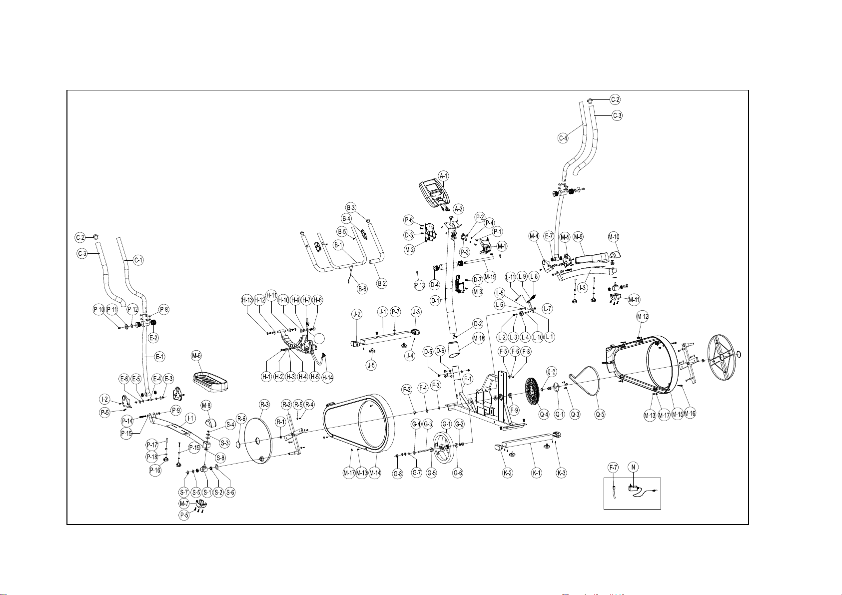
L-1~L-11 Idler wheel set 1SET
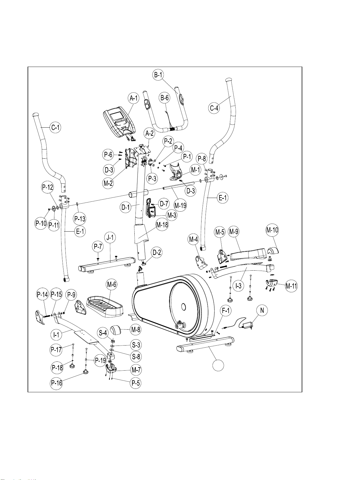
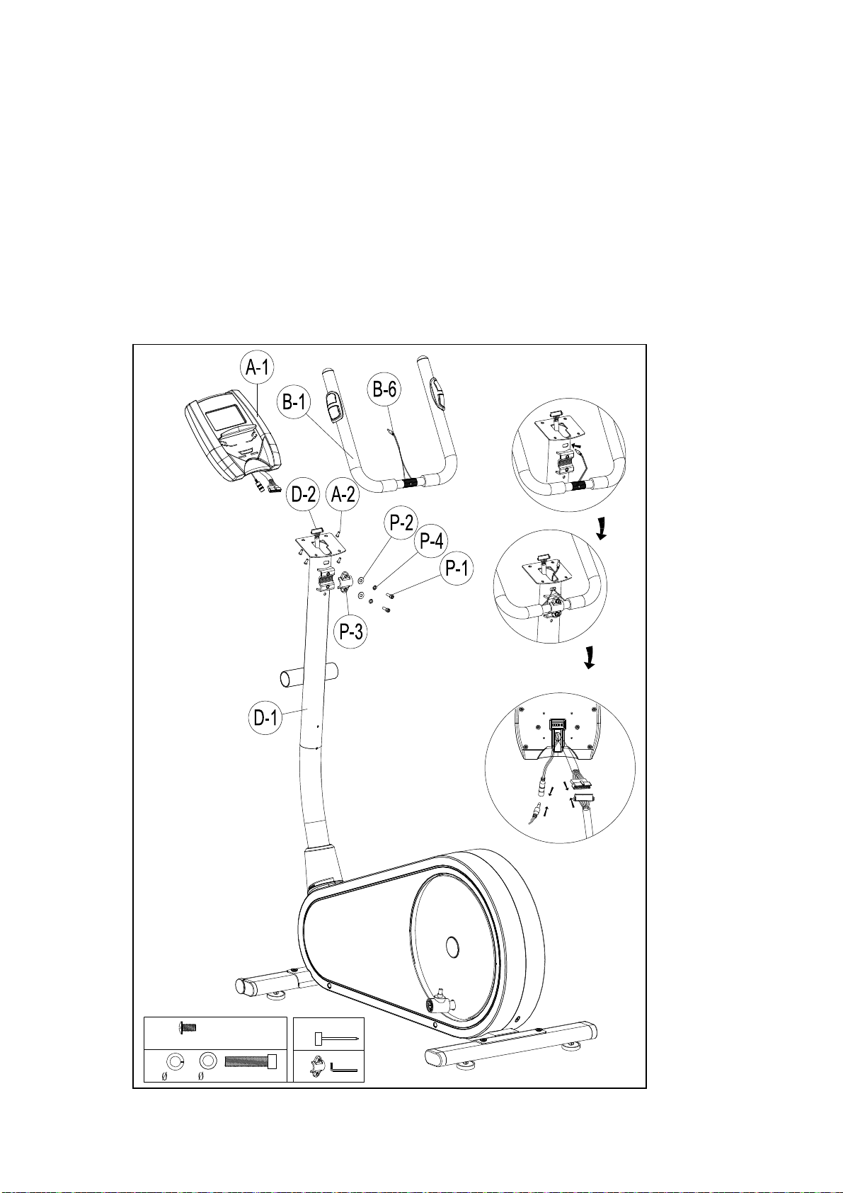
M-1 Front cover for computer 1PC
M-2 Rear cover for computer 1PC
M-3 Bottle holder 1PC
M-4 Front cover (Left) for pedal post 2PCS
M-5 Front cover (Right) for pedal post 2PCS
M-6 Pedal (Left) 1PC
M-7,M8 Left rear cover (upper/down) for pedal post 1SET
M-9 Pedal (Right) 1PC
M-10,M-11 Right rear cover (upper/down) for pedal post 1SET
M-12 Screw for chain cover M4x50L 5PCS
M-13 Screw for chain cover M5x16L 6PCS
M-14 Left chain cover 1PC
M-15 Right chain cover 1PC
M-16 Cap for chain cover screw holes Oval 5PC
M-17 Cap for chain cover screw holes Round 4PC
M-18 Cover for handlebar post 1PC
M-19 Axle for first-lower handlebar 1PC
N Adaptor 1PC
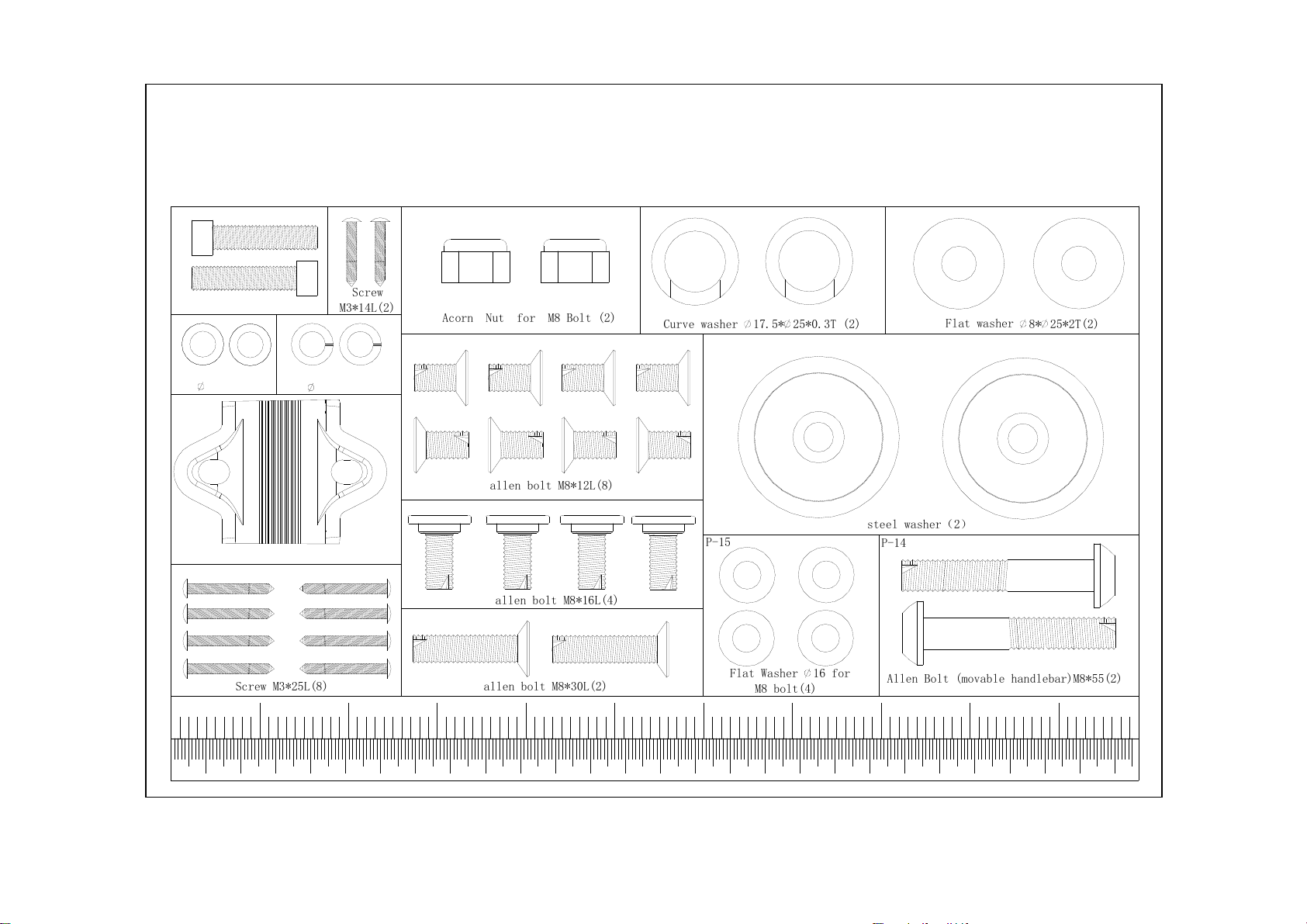
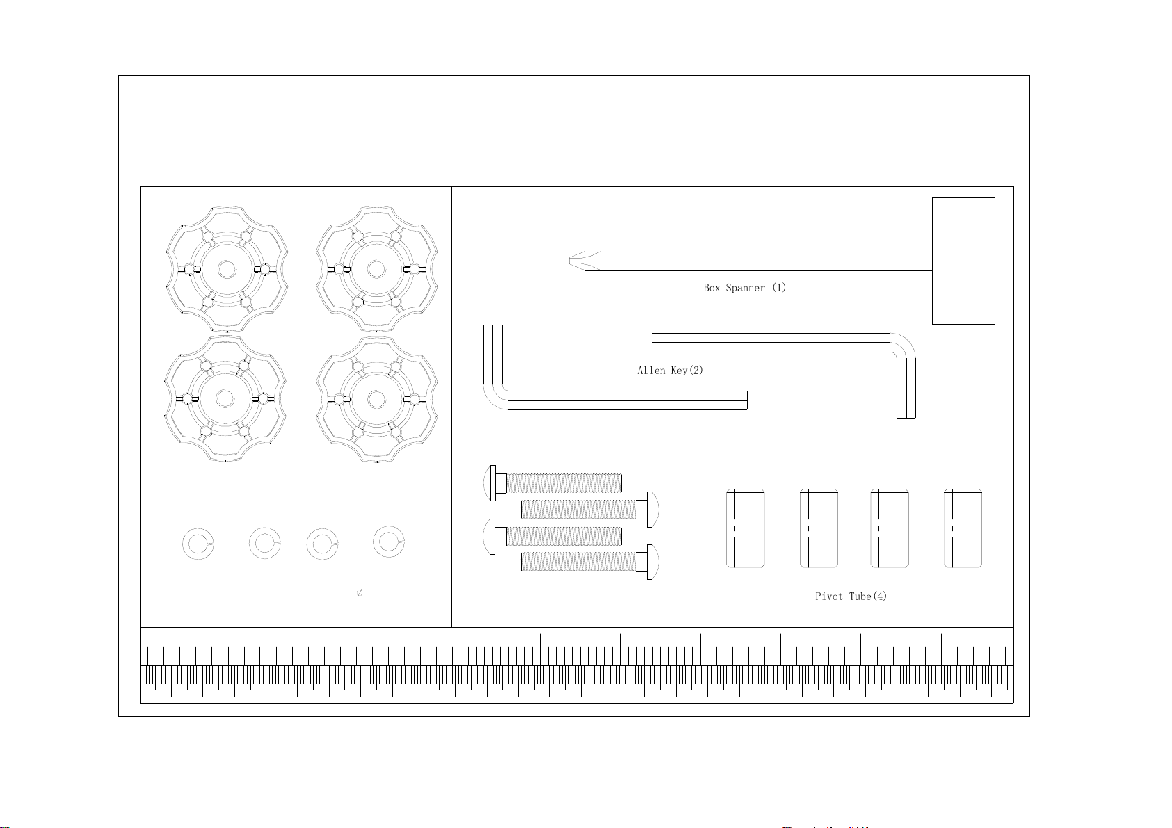
P-1~P-19 Bolts & nuts pack 1SET
Q-1 Shaft 1PC
Q-2 Bushing φ20.5xφ25x7.5mmL 1PC
Q-3 Hexagonal screws M8xP1.25x12Lx5t 3PCS
Q-4 Big pulley 1PC
Q-5 Belt J6 1219m/m 1PC
R-1 Nut M10xP1.25x10T 2PC
R-2 Cross disc 2PCS
R-3 Round disc 2PCS
R-4 Screw M4x14L 8PCS
R-5 Flat washer φ5xφ16x1t 9PCS
R-6 Cap for round disc 2PCS
S-1~S-8 Crank connation set 2SET

9
ASSEMBLY STEPS
STEP 1
Attach the Front Stabilizer (pt.J-1) to the Main Frame (pt.F-1) using two Allen bolt (pt.P-7)
Attach the Rear Stabilizer (pt.K-1) to the Main Frame (pt.F-1) using two Allen bolt (pt.P-7).
STEP 2
1. Please remove four sets of the M8x16 Allen bolt (pt.D-5) and Flat Washer (pt.D-6)from
the Main Frame (pt.F-1)
2. Take the Handlebar post (pt.D-1) and pass it through the Handlebar post cover (pt.M-
18).
3. Hold the Handlebar Post (pt.D-1) and connect the Lower Computer Cable (pt.H-14)
and the Upper Computer Cable (pt. D-2)
4. Slide the Handlebar Post (pt.D-1) into the Main Frame then fix with four sets of M8x16
Allen bolt (pt.D-5) and Flat Washers (pt.D-6)
.
M8*16L
4* 1*
K-1
Ø12*Ø19*1T M8*16L
4* 1*

10
STEP 3
1. Attach the Front handlebar (pt.B-1) to the Handlebar post (pt.D-1) using the clamp
cover (pt.P-3), and then fix with two Flat Washers (pt.P-2), two Spring Washers (pt.P-4),
two Fixing Bolt (pt.P-1).
2. Pass the hand-pulse wire (pt.B-6) through the hole.
3. Connect the Computer cables (pt .D-2) and connect the Hand pulse wire (pt.B-6), then
attach the Computer (pt .A-1) to the Computer bracket with the enclosed Screws (pt .A-
2).
2* 7*2T 7*1T M7*30
M5*10
4*1*
1*

11
STEP 4
1. Remove the pre-installed Screws (pt.D-3) on the handlebar post first.
2. Attach the Rear cover (pt.M-2) using two of Screws (pt.P-6) and one of Screws
(pt.D-3) .
3. Attach the Front cover (pt.M-1) using Screws (pt.D-3)
4. Remove the pre-installed Screws (pt.D-7) on the handlebar post, and then assemble
the Bottle holder (pt.M-3) by Screw (pt. D-7).
1*
M5*14
2* M5*20
2*

12
STEP 5 Fix the two Lower handlebar (pt.E-1) to the Handlebar Post (pt.D-1) with
one Axle (pt.M-19), two sets of Wave washer (pt.P-13), Flat washers (pt.P-
12) and Gasket (pt.P-11) and Allen bolt (pt.P-10).
Pay attention : Please use two allen key tools to fix bolt ( P-10 ) on both side at the same
time.
M8*30L
steel washer
2* 1*
Ø17.5*Ø25*0.3TØ10*Ø26*2T

13
STEP 6
1. Attach the Left and Right lower Handlebar (pt.E-1 L/R) to the Left and Right pedal
post (pt.I-1 & I-3) using two Allen bolt (pt.P-14), four Flat washers (pt.P-15) and two
Nylon nuts (pt.P-9). --- Figure A
2. Attach the Pedal post (pt.I-1 & I-3) onto the Crank connation set using one of Nylon
nuts (pt.S-4), Flat washers (pt.S-3) and Plastic washers (pt.S-8). --- Figure B
3. Connect the Right rear cover (upper) (pt.M-8) and Right rear cover (lower) (pt.M-7) to
the Left pedal post (pt.I-1) using screw (pt.P-5). --- Figure C
4. Connect the Left rear cover (upper) (pt.M-10) and Left rear cover (lower) (pt.M-11) to
the Right pedal post (pt.I-3) Using screw (pt.P-5).
.
B
C
M8*55
M3*25L
M8
M8
2*
4*
6*
1*
A

14
STEP 7
1. Remove the pre-installed screws (pt.I-2) on the Pedal post first.
2. Attach the Lower handlebar (E-1 R/L) to the left and right pedal post (I-1), and then
close the cover (M-4 & M-5) using screws (pt.P-5 & I-2).
3. Assemble the Right pedal (pt.M-9) onto the Pedal post (pt. I-3) with 2 Knobs (pt. P-16),
2 Spring washers (pt.P-18),2 Bushings (pt.P-19) and 2 Carriage bolts (pt.P-17).
4. Assemble the Left pedal (pt.M-6) onto the Pedal post (pt. I-3) with 2 Knob (pt. P-16), 2
Spring washers (pt.P-18),2 Bushings (pt.P-19) and 2 Carriage bolts (pt.P-17).
M5*14
M3*25L
M6*P1.0*40L M6
4* 2* 4* 1*
Ø6Ø7*Ø12*25
E-1

15
STEP 8 Slide the Upper handlebar post (C-1,C-4) (R/L) into the Lower handlebar (E-1)
and then fix with the eight Allen bolts (P-8)
STEP 9
Connect the adaptor (N) to the DC hole (located on the back of the chain cover).
M8*12L
8*
1*
E-1

16
SM1705-67 INSTRUCTIONAL MANUAL
For simple exercise, it is not always necessary to select a training program or manually set the
TIME, DISTANCE or other values. You can simply start work out.

17
As soon as the computer is connected with power supply, an acoustic signal sounds and all of the displays
are shown on LCD for 2 seconds, then showing wheel diameter.
If no button are pressed and the pedals have not been moved for approx. 4 minutes, the
computer will switch to power saving mode. All setting and data will be saved until user
start next training.
DISPLAY & BUTTON FUNCTIONS
Training Values Display Range Description/ Setting Range
RPM 0~999 -Revolution per minute
TIME 0.0 ~ 99:99min. -User exercising time displaying;
-Setting range 0:00~99:00.
SPEED 0~99.9km -User exercising speed.
DISTANCE 0~99.99m -User exercising distance.
- Setting range 0.00~99.90km
CALORIES 0 ~ 9999 Cal. -Burned calories during exercising.
-Setting range 0~9990
WATT 0~999 -Power consumption during exercising.
-Setting range 10~350
PULSE 30-230 BPM -User current Heart Rate value.
-Setting range 0-30~230Bpm.
Acoustic Signals
All settings made with the computer are confirmed with an acoustic signal:
1 shot beep = setting confirmed
BUTTON FUNCTION
UP - Increase resistance level
- Function selection
DOWN - Decrease resistance level
- Function selection
ENTER - Confirm setting or selection.
Reset - Hold on pressing for 2 seconds, computer will reboot.
- Reset all values to zero.
- Reverse to main menu after finishing a workout.
Start/ Stop - Start or Stop training.
Recovery - Track user Heart rate in recovery phase.

18
2 shot beeps =It is impossible to make any settings
Training Data
The computer calculates and displays all values automatically according to user exercising status
(see table).
Take note:
* If only a “P” is shown instead of pulse value, it is impossible to measure the HR. Keep both hands
holding on the handbar properly so that computer can detect your hear rate.
* The profile displayed in the center field depends on the type of exercise that has been set.
The computer provides a number of ways to vary the exercise session and make it more motivating.
The following exercising are available:
-Manual Training (training without programs)
-Training with Programs (there are 12 programs preset, P01~P12)
-Training with the Heart Rate program (H.R.C)
-Training with USER program (set your own desired profile)
-Training with WATT program (Power consumption)
Starting exercise immediately (MANUAL)
Then MANUAL is flashing with 1Hz. Press UP or DOWN to choose MANUAL and confirm by
pressing ENTER. If you have previously selected a program or started your workout, press
RESET to return to the starting display.
-Press START/STOP button to start workout immediately without entering further settings.
-Press UP and DOWN keys to input your personal settings and press ENTER to confirm. The following
fields will flash in turn:
. Resistance level (1~16)
. TIME
Hand sensor
for pulse measurement

19
. DISTANCE
. CALORIES
. PULSE
Use UP & DOWN to set values and confirm your selection by ENTER button.
Press START/STOP button to start workout.
As soon as one of the set values reach the preset Target, the computer will alarm with Bi-bi sound and
stop.
-You can adjust the level of resistance on the pedals while exercising by pressing UP and DOWN keys.
The newly set level value will be shown in the profile(default value is Level 1).
-Press START/STOP button to end exercising. All exercising value will remain.
-Press RESET to reverse to workout selection menu.
Selecting a Program to do training (PROGRAM)
-Press UP and DOWN keys to scan MANUAL→PROGRAM USER PROGRAMHRCWATT.
-Choose PROGRAM and press ENTER to confirm. The programs are preset with 12 profiles. Press UP
and DOWN to select one from the 12 preset profiles. Set the desired session value and confirm by
ENTER:
. Resistance level (1~16)
. TIME
-Press STATR/STOP to start workout.
-You can adjust the level of resistance on the pedals while exercising by pressing UP and DOWN keys.
The newly set level value will be shown in the profile(default value is Level 1).
-Program profile & intensity:
Interval programs P2- P3- P7- P12
Increasing resistance level programs P6- P9- P11
Increasing and decreasing resistance level programs P1- P4- P5- P8 -P10
The stored training programs are designed especially to enhance aerobic base fitness.
. As a beginner you should start with those programs slowly and set a low pedal resistance.

20
. You should only graduate to Interval programs once you have exercised for several times.
-Press START/STOP button to end exercising. All exercising value will remain.
-Press RESET to reverse to workout selection menu.
User-defined profile (USER PROGRAM)
Here you can design your own profile with bars just like the preset program profiles.
-Press UP & DOWN to select USER PROGRAM and press ENTER to confirm. The first bar will be
displayed.
-Press UP & DOWN to set resistance level and confirm by ENTER button. The next bar will be displayed.
-Continue this process till set up 20 bars. The max. resistance level is 16. When come to 9th bar, it scroll
and shift tonext and so on. To finish your setting or quit setting, hold on pressing ENTER button.
-Set the desired session TIME with UP & DOWN buttons and press ENTER to confirm.
- Press STATR/STOP to start workout.
-During the program profile setting, user may press MODE to finish or holding it for 2s to quit
setting.
-You can adjust the level of resistance on the pedals while exercising by pressing UP and DOWN keys.
The newly set level value will be shown in the profile(default value is Level 1).
-As soon as one of the set values reach the preset Target, the computer will alarm with Bi-bi sound and
stop.
-Press START/STOP button to end exercising. All exercising value will remain.
-Press RESET to reverse to workout selection menu.
Set program according to heart rate (H.R.C.)
In this program, the console reacts to your pulse as measured by the metal handbar.
This program allows you to exercise efficiently and safely within your required heart rate zone.
In addition, simple graphics also show you whether you need to need to increase or decrease your stress
Level. You can choose between:
HRC55 Here you are exercising in the very efficient range of 55%, ideal for beginners and for general fat
Burning.
HRC75 This range of 75% of the maximum pulse rate is suitable for experienced users and athletes.
HRC90 The anaerobic range of 90% of the maximum pulse rate is only suitable for competitive athletes
and short sprint exercises.
TAG The computer uses your Age to calculate a target pulse rate, which you can change as per your
willing. Never select a target pulse that is higher than your age-determined maximum pulse rate.
-Press UP & DOWN to select H.R.C. and enter by pressing ENTER. Choose HRC55-->HRC75
-->HRC90-> TARGET. With HRC55, HRC75,HRC90, the max. Heart rate will be calculated by
This manual suits for next models
1
Table of contents
Other Casall Elliptical Trainer manuals