AFS-8036-13e Replaces: None
© 2013 CNH America LLC. All rights reserved. Printed in U.S.A.
Case IH is a registered trademark of CNH America LLC. Any trademarks referred to herein in
association with the goods and/or services of companies other than CNH America LLC are the
property of those respective companies.
CNH America LLC reserves the right to make improvements in design and changes in
specifications at any time without notice and without incurring any obligation to install
them on units previously sold. Specifications, descriptions and illustrative material herein
are as accurate as known at time of publication, but are subject to change without notice.
Availability of some models and equipment builds varies according to the country in which
the equipment is used.
Visit us on the web at www.caseih.com
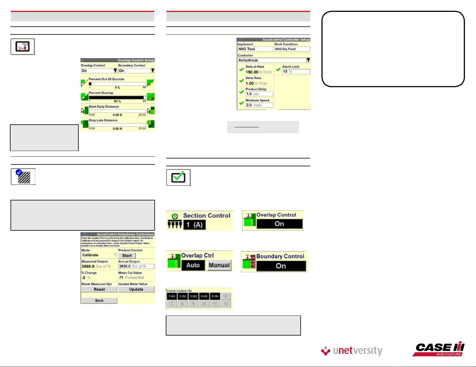
7 - OVERLAP/BOUNDARY CONTROL
7.1 Overlap/Boundary Control
Toolbox>Overlap
a) Turn overlap control on
b) Turn boundary control
on (requires a created
boundary)
c) Set % for out of bounds
d) Set % of overlap
for shutoff
e) Set start early
distance to 0 ft.
f) Set stop late
distance to 0 ft.
IMPORTANT! Product delay
must be measured and set
correctly before adjusting
start early/stop late values.
7.2 Product Delay Adjustment
Work Condition>Control>Liquid
Before making any adjustments to the Product
Delay, make sure GPS offsets & Bar Distance are
entered correctly.
To check performance:
Note: Prime can be used to perform this calibration (start at
step g), but may not be available on the run screens. The NH3
calibration screen will be used to check the product delay in
this case. Instructions below are for using the liquid calibration
method to check product delay.
a) Select Work
Condition>Liquid Cal
b Select Liquid Op Mode
– [Anhydrous] (Accept
Safety Warning if agreed)
c) Press Master Control –
‘Apply’ Button
d) Press ‘Next’, twice
e) Press the Start button
once to prime the system,
Press ‘Stop’
to stop operation
g) Start the stopwatch and
at the same time Press
the ‘Start’ button
h) Stop the stopwatch when product is rst observed leaving the
application point
i) The elapsed time displayed on the stopwatch is the
Product Delay
7 - OVERLAP/BOUNDARY CONTROL – continued
7.3 Running Overlap/Boundary Ctrl
NOTE! The following windows can be located
on the Run screens.
Disengages drive section master
valve and/or all boom valves for that
drive section. “On” when the button
is black (1), and “Off“ when the button
is grey (2)
Quickly switch between Auto and
Manual section control
Enables/Disables Overlap Control
(disable before backing, enable after
driving forward), except AccuGuide
complete tractors
Enables/Disables Boundary Control
Disengage individual section valves
NOTE! (A) must be present for Auto Overlap and Boundary
Control to function. If (M) is present, Auto Overlap and
Boundary control will not work!
7.2 Product Delay Adjustment - continued
j) Exit the calibration
without updating the
calibration number
by pressing ‘Back’
k) Press ‘Control’ Tab
l) Enter the measured
time as the Product
Delay gure
m) Throughout the season
check for proper overlap
operation especially when
experiencing different
ambient temps
n) If exact measurement of
error is determined use this
formula to convert this
distance to a new
Product Delay (PD)
o) Adjust Start Early/Stop Late distance for intentional
overlap. If a negative number seems to be required for
SE/SL, re-measure & adjust Product Delay
TIPS
1. A data card must be inserted in to the display.
2. Check GPS Offset, Bar Distance, Product Delay, and
check that a product is assigned to a layer for Overlap
& Boundary control to function properly.
3. “(A)” must be present in a window for Auto mode.
4. Disable Overlap Ctrl before backing into corners,
etc. Re-enable after moving forward (not required for
AccuGuide Equipped Tractors).
= new PD (sec)
Ft. of error
mph X 1.46