Introduction, General REFLECTA/1
Page A4 Mounting & Operations Manual
Alterations / Errors reserved
Cassens & Plath GmbH, Kompasshaus, Am Lunedeich 131, 27572 Bremerhaven, Germany, tel +49 471 4839990, fax +49 471 48399910
Intended Purpose
Apart from the gyro compass seagoing ships have to be equipped with a second heading source, the magnetic
compass. Furthermore the magnetic compass works more and more as back-up to drive the autopilot.
Magnetic compasses have to be installed in a sufficient distance to any magnetic iron as well as to the different
navigational instruments. Therefore the preferred location is the compass bridge. To read the heading at the
helmsman´s position inside the wheelhouse one makes use of a reflection arrangement. This is an optical
arrangement consisting of magnification lenses and mirrors. According to SOLAS regulations the remote
reading has to be independent of electrical means.
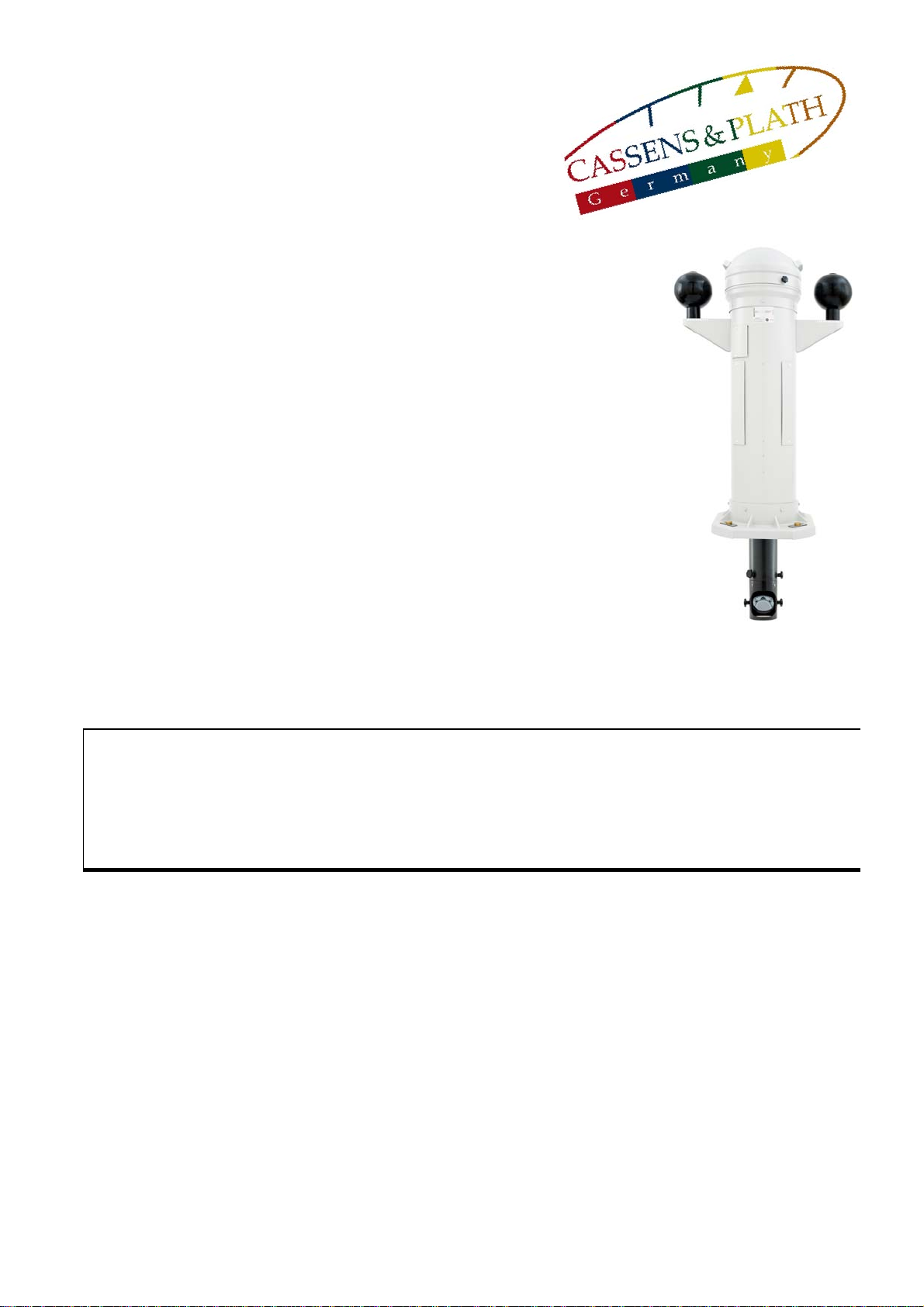
The magnetic compass is found within the compass binnacle. It is easy to remove and to replace with another
one. Spare magnetic compasses are obligatory according to SOLAS.
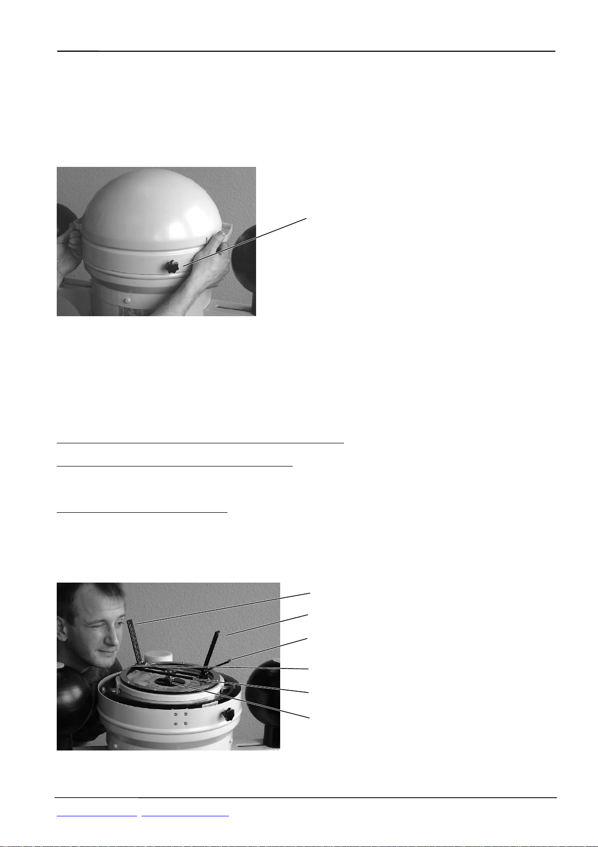
A divided verge ring on top of the compass allows taking bearings of coastal or heavenly objects. A vane type
azimuth device with a swivel black mirror is included in the range of delivery to allow compass and relative
bearings.
In spite of the distance to any magnetic source a deflecting influence -the deviation- cannot be totally excluded.
For correction of these residual errors the compass binnacle possesses an adjusting arrangement.
Installation of magnetic compasses and the requirements for their location are laid down in basic national and
international regulations. These are IMO A.382(X) and SOLAS consolidated Edition, 1992, Chapter V,
regulation 12. The technical and design requirements for magnetic compasses are laid down in ISO
25862:2009(E) amendment: Directive 2010/68/EC + 2011/75/EC as well as in the relevant national documents.
REFLECTA fullfills all these regulations.
Technical Data
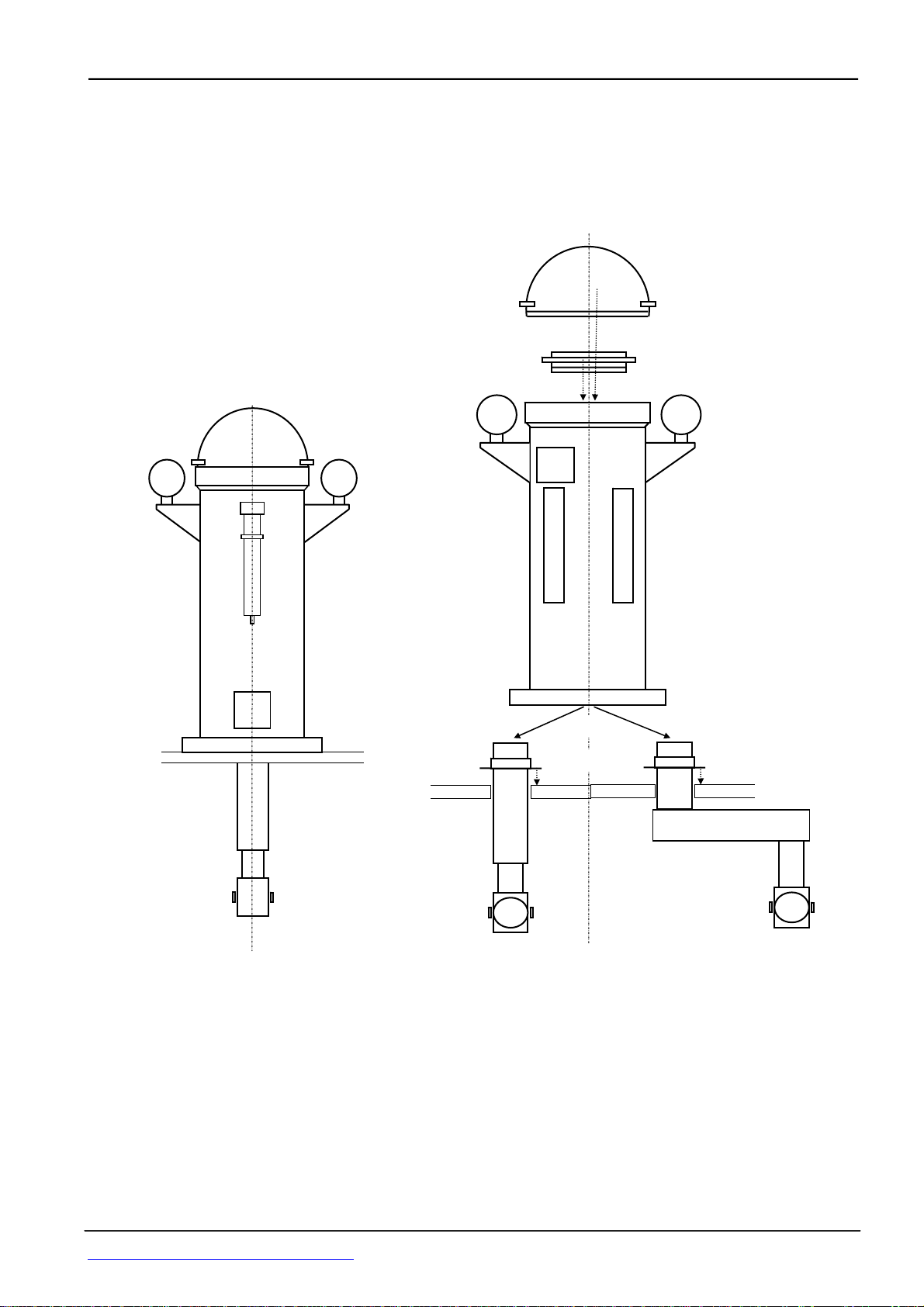
Compass Binnacle
Card height............................................. standard column 1200 mm, as option 910 mm up to 1800 mm
Total height.....................................................................................1380 mm in case of standard column
Maximum width measured over D-spheres..................................................................................880 mm
Weight of binnacle and compass complete....................................net 95 kg in case of standard column
Material of binnacle column..........................................................................seawater resistant light alloy
Built-in correctors.......................................................................................................................B+C, K, D
Correctors as option................................................................................................................................E
Correctors as option..............................................................................................................Flinder´s bar
Reflector/bearing compass type 11
Diameter of directional system..................................................................................................... 180 mm
Orientations of card printing from below for reflection reading .................................................N below N
Card division........................................................................................................................................1/1°
Magnet................................................................................................................................................Ring
Magnetic moment...............................................................................................................typically 4 Am2
Damping factor ....................................................................................................................... typically 3.3
Working temperature range............................................................................................. -30°C .... +65°C
Swirl error according to ISO 25862:2009(E)/2010/68/EC+2011/75/EC, 2013/52/EU........< 2,0°(at18µT)
Friction error according ISO25862:2009(E) 2010/68/EC+2011/75/EC, 2013/52/EU..........< 0.5°(at 6µT)
Directional error according ISO25862:2009(E) 2010/68/EC+2011/75/EC, 2013/52/EU ..< 0.5°(at 18µT)
Half period .......................................................................................................................................13 sec
Tilt freedom of card in compass bowl.............................................................................................+/- 10°
Rolling/pitching tolerance of compass in gimbal suspension........................................................+/- 180°
Weight................................................................................................................................................12 kg
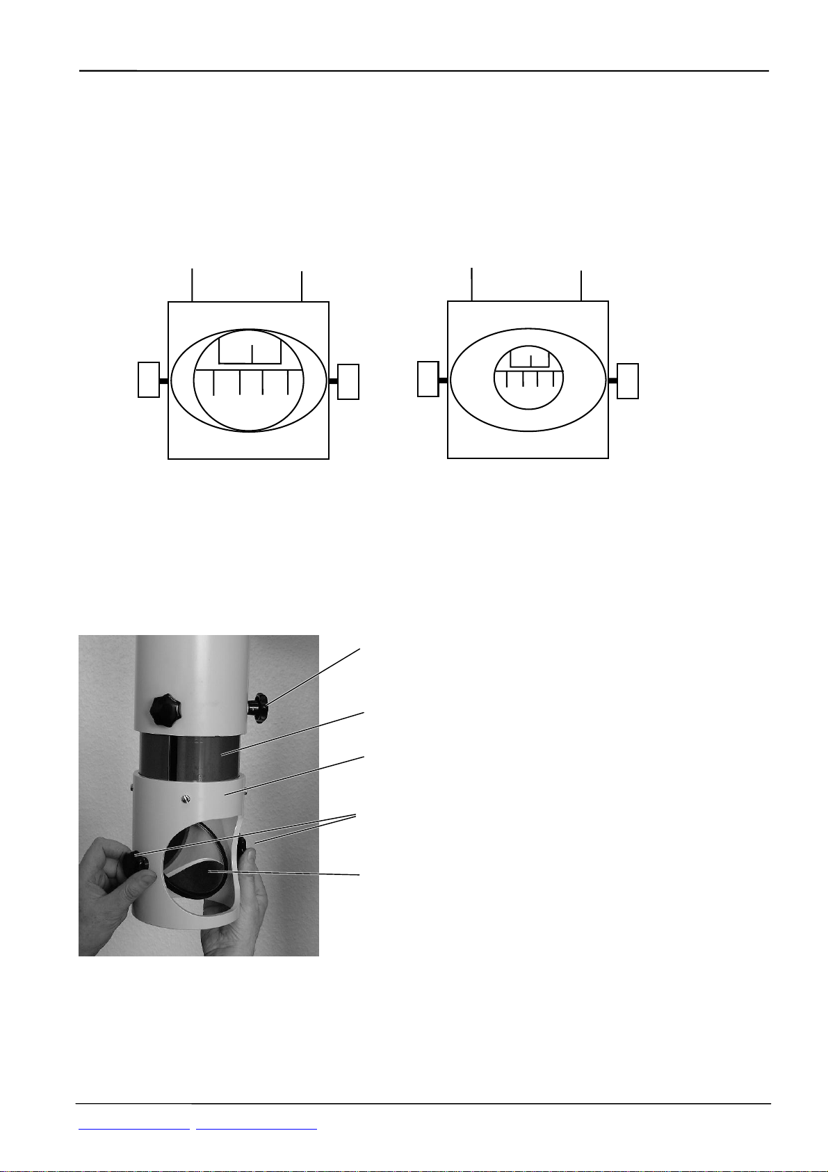
Reflection arrangement
Type CUTUBE .....................................................................................length 1200 mm to be cut by yard
Type FIXTUBE................................................................................... ready adjusted in length at delivery
Diameter of tube........................................................................................................................... 140 mm
Material...............................................................................................................................................PVC
Extension length of mirror head.................................................................................................... 150 mm
Turning range of mirror head..............................................................................................................360°
Swivel range of reflection mirror, black and white..............................................................................360°