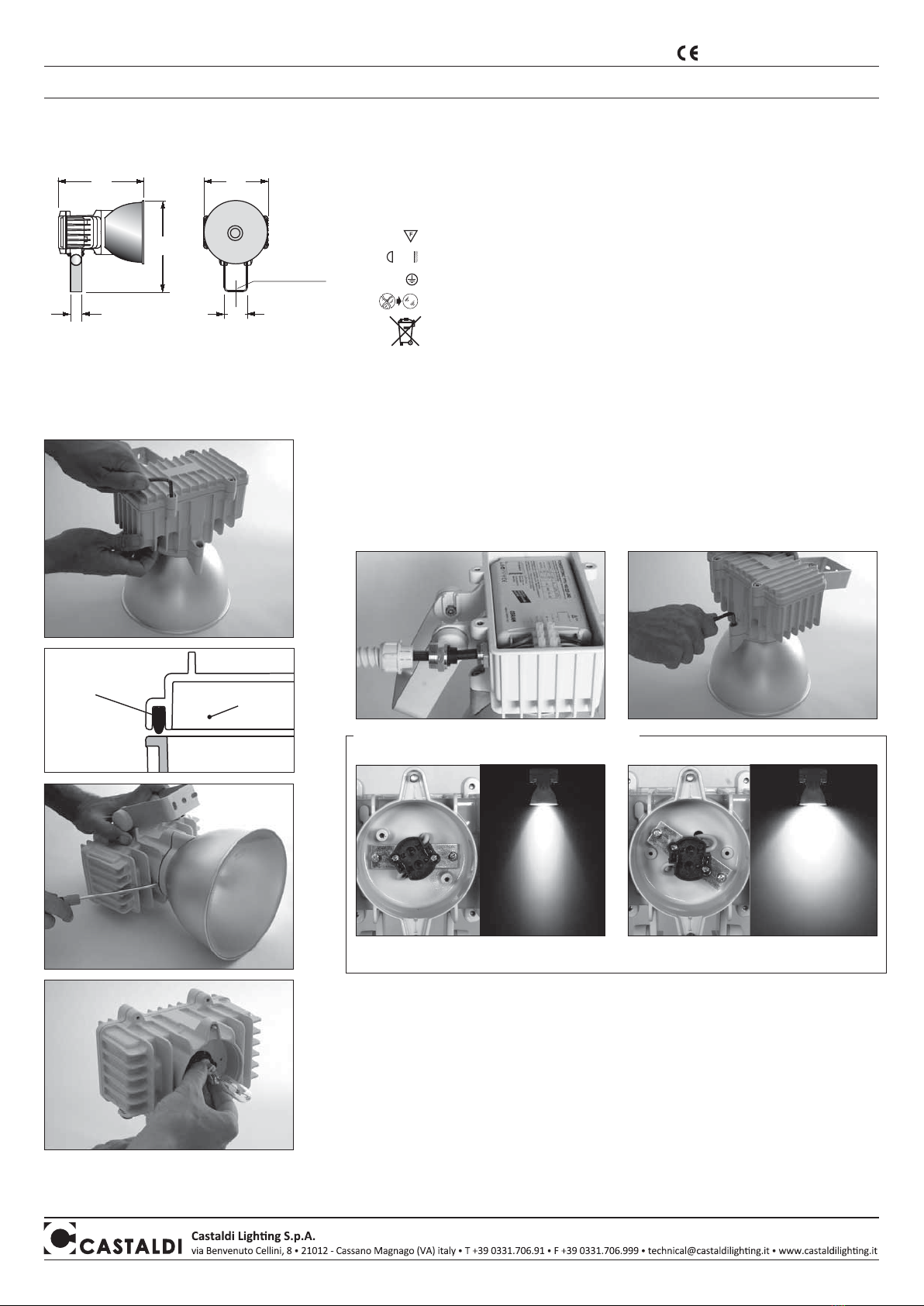
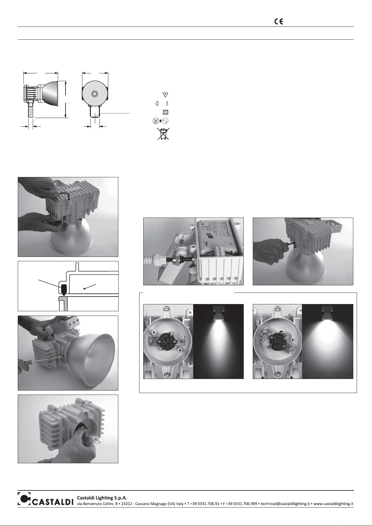
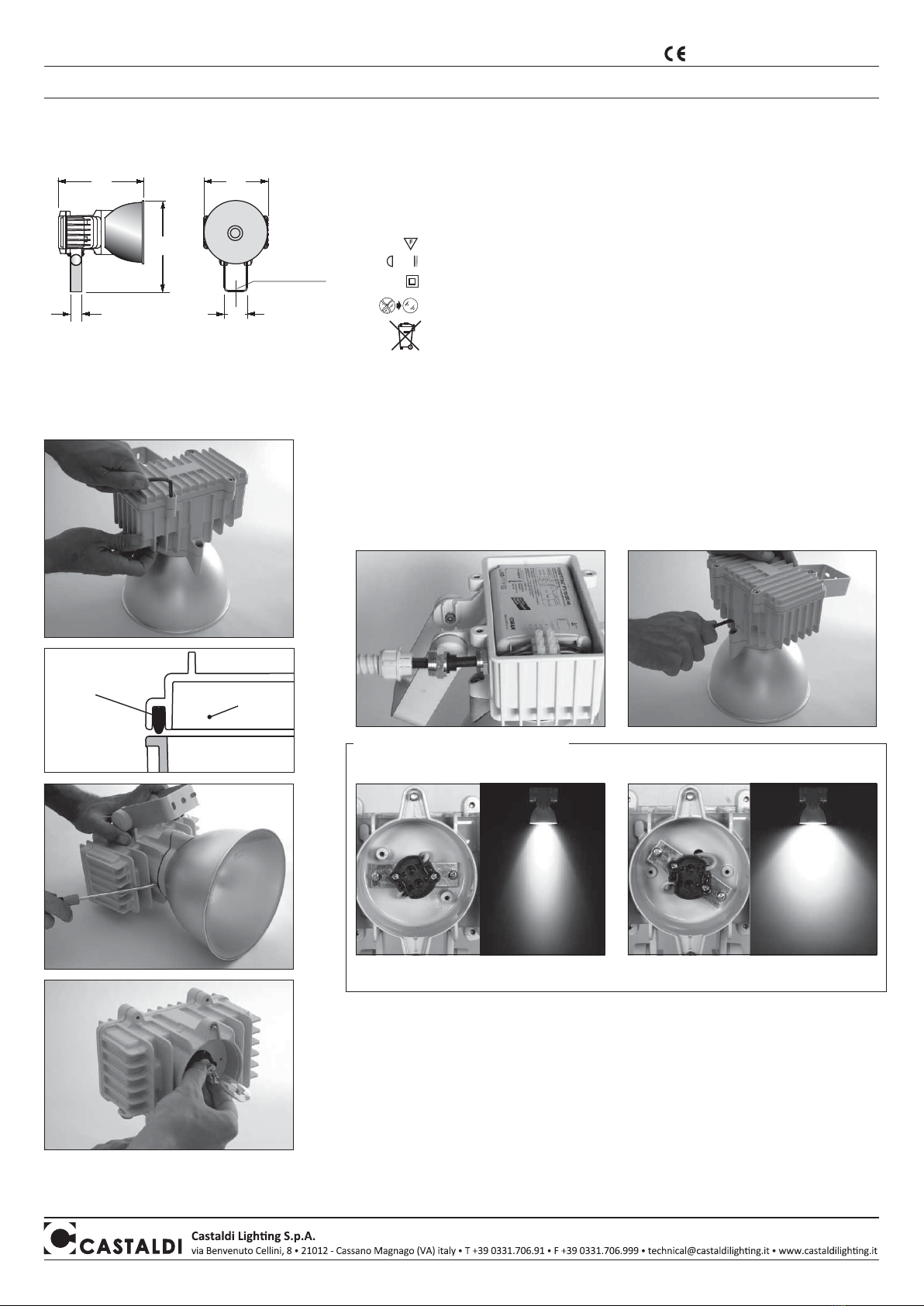
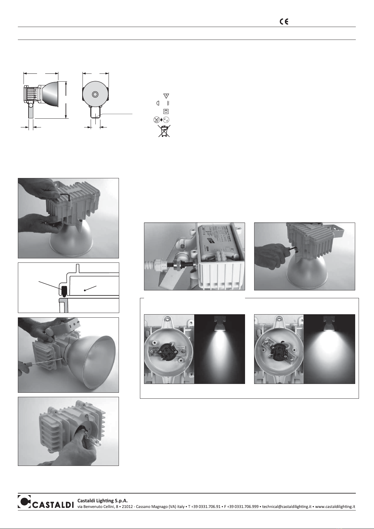
Eigenschaften - Bedeutung der Symbole auf dem Typenschild:
Die Leuchte ist für den Innen sowie den Aussenbereich geeignet
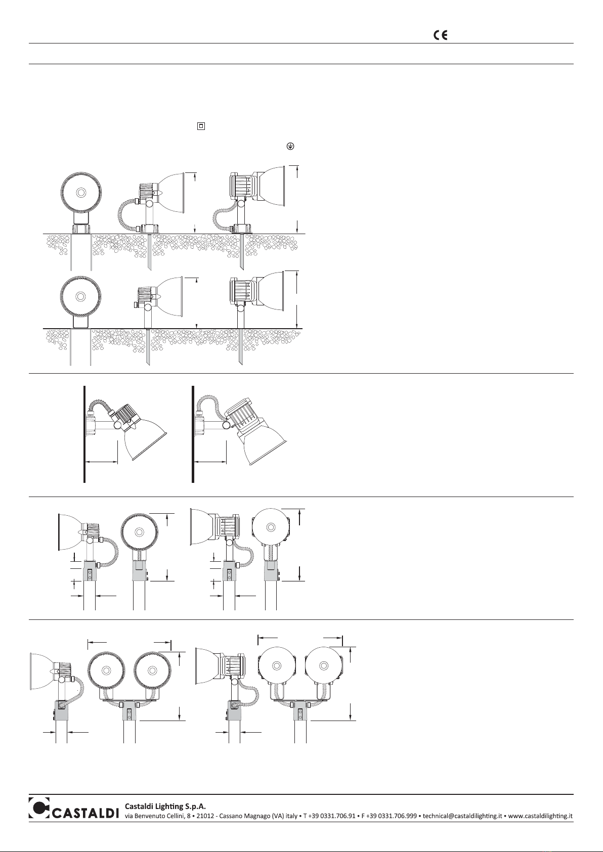
Montage auf Wand, Decke, Boden, Struktur oder Mast
IP66 Absolut staubdicht - Schutz bei Überflutung
Geeignet für Montage auf normal entflammbaren Befestigungsflächen
Minimalabstand zwischen Leuchtkörper und beleuchtetem Gegenstand
Klasse I mit Schutzleiteranschluss
die beschädigten Schutzgläser ersetzen
Das Entsorgen im Hausmüll ist verboten!
Bei Ablauf der Lebensdauer bitte beachten: Abfalltrennung ist Pflicht
Installation:
• Bei Aussenmontage ist es Pflicht (CEI EN 60598-1; CEI 20-40/CENELEC HD516S1) biegsames dreipoliges
Kabel aus Neoprengummi Typ H07RN-F mit Durchmesser zwischen 9 und 12mm zu verwenden.
Es sind keine Kabel mit PVC - Isolierung oder mit externem Hülsen aus PVC, jedenfalls anderen als die hier
angeführte Kabeltype zulässig.
N.B.: passendes Kabel lieferbar auf Anfrage.
• Zum Öffnen des Gerätes die beiden in Abbildung 1 angezeigten Schrauben lösen.
• Einsetzen des Kabels mit der Kabeldichtung in die Verschraubung und Anschließen an den 3-adrigen
Anschlussblock. Hierbei auf die Pole achten (Abb. 2). Vorsichtig die Dichtung am Leuchtenkopf mit dem
Kabel H07RN-F festziehen, dann die Verschraubung ø 14-19mm auf dem Dichtungsanschluss befestigen
und wiederum vorsichtig festziehen. (Abb. 2). Die Abdeckung wieder aufschrauben, dabei sicherstellen,
dass die Dichtung in Ordnung ist und die aufliegende Oberfläche sauber. (Abb. 4).
• Lösen der Verbindungsschrauben des Reflektors (Abb.3).
•
Mit einem Schraubenzieher an verschiedenen Punkten anheben um den Körper vom Reflektor zu lösen (Abb. 5).
• Einsetzen des Leuchtmittels (Abb. 6) unter Beachtung des Lampentyps und der Wattage, wie angegeben
auf dem Label, gemäß der gewünschten Version “A” oder “B”
•
Zusammenfügen des Leuchtenkörpers mit dem Reflektor und die zwei Befestigungsschrauben anziehen (Abb. 3).
LED VERSION - RISIKOGRUPPE 2:: WARNUNG: dieses Produkt kann gefährliche optische Strahlun-
gen emittieren. Schauen Sie nicht in die Lichtquelle, kann Ihre Augen schädigen. Zum Einkaufen der
Led-Lampe, wenden Sie sich an unsere Firma oder an unsere Verkaufsorganisation. Die Auswechse-
lung muss von einem qualifizierten Installateur angefertigt werden.
LAMPENAUSTAUSCH - WARTUNG:
• Ersetzen Sie die Lampe rechtzeitig am Ende ihrer Funktionsdauer und beachten Sie dabei auf dem Schild
ausgegebene Leistung und Typ. Die den Lampen beigelegten Gebrauchsanweisungen aufmerksam lesen
und beachten. Bevor Sie das Gerät offnen, müssen Sie gründlich reinigen.
Verformte oder nicht in einwandfreiem Zustand befindliche Dichtungen müssen ausgetauscht werden.
• Das Glas der Leuchte sowie alle Aussenflächen des Gerätes müssen regelmässig gereinigt werden,
so dass Ablagerungen von Erde oder Schmutz ausgeschlossen sind. Die o.a. Ablagerungen beinhalten die
Gefahr einer Überhitzung und verhindern die Vorschriftsmässige Lichtabstrahlung und Wärmedissipation.
Eventuell auf dem Glas präsente Kalkablagerungen können mit einem Schaber entfernt werden.
P
• windausgesezte Fläche: 0,036m
2
• Gewicht D26R/MH: MH20 = 1,8Kg Gewicht D26/MH: MH35 = 3,1Kg
MH35 = 1,8Kg MH70 = 3,6Kg
D26R/LW: 1,8Kg MH150 = 4,5Kg
• Montagehöhe: beliebig
Abb. 1
Abb. 6
Abb. 3
Abb. 5
Abb. 2
N.B.: Die Fassung in “A” Position bedeutet Lichtstrahl “A” (intensiv).
Die Fassung in “B” Position bedeutet Lichtstrahl “B” (halb-diffus).
AB
KROHPP
(D26R/MH - 230mm) (D26R/MH - 165mm)
(D26R/MH - 62mm)
(D26R/MH - 210mm)
Abb. 4
Dichtung Abdeckung
Loch Ø 8,5 mm
Montageanleitung - Instandhaltung D26 gulliver/MH - D26R gulliver R/MH
Das Produkt entspricht den Richtlinien
der Europäischen Gemeinschaft
NOTA BENE: Vorliegende Montageanleitungen müssen auf jeden Fall dem Endverbraucher übergeben werden, damit dieser über die korrekten Wartungs- und Lampenaustausch-
modalitäten informiert ist. Jegliches Aufbrechen und/oder Änderung der Leuchte ist verboten. Die Leuchte muss wie geliefert und entsprechend den anlagentechnischen Lande-
svorschriften montiert und verwendet werden. Nichtentsprechende Installationen führen zum Verfall von jeglicher Garantie. Das Unternehmen übernimmt keine Verantwortung für
Schäden, die durch fehlerhafte Montage verursacht sind.
NUR FÜR DAS D26 gulliverr/MH MODELL:
Qualitätskontrolle: Sollten Sie Reklamationen haben, wenden Sie sich an unsere Firma oder an unsere Verkaufsorganisation unter Angabe des Bestelldatums und
der Kennummer des Geräts.