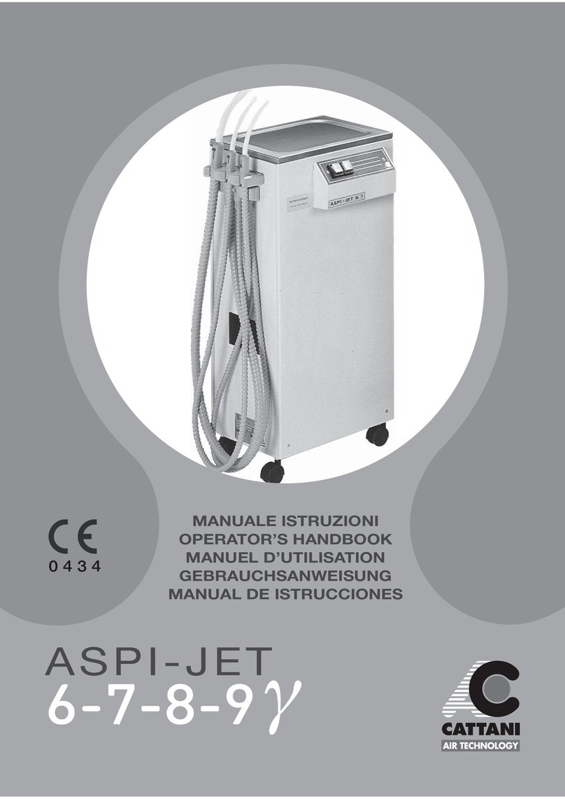
Cattani ASPI-JET 6 y Service manual

WE LOVE WHAT WE DO.
0425
english
Operator’s handbook
ASPI-JET
6-7-8-9

2

3
cod: ed. 10-2021
ENGLISH
General running data 4
Legend of components 6
Certification of medical equipment according to directive 93/42/CEE 8
Introduction 9
Signals 9
Recommendations 9
General features 10
General installation and starting tips 10
Installation 11
Operation and use 12
Notice 13
Maintenance and cleaning 13
Main cleaning and maintenance operations 15
Notice 15
Maintenance operations meant for engineers 15
Important notice 17
Transport and storage 17
Transport of second-hand appliances 17
Waste disposal 18
Electromagnetic compatibility conformity levels per EN 60601-1-2:2015 standard 19
INDEX

4
cod: ed. 10-2021
*Sound pressure level tested according to ISO 3746-1979 (E)
regulation.
Parameters: r or d=1,5 - Background noise < 38 dB (A) - Instruments:
Brüel & Kjær Type 2232.
GENERAL RUNNING DATA
DENTAL ASPIRATOR
Model Aspi-Jet 6-7-8-9 γ
Rated voltage 230 V
Rated frequency 50 Hz
Rated current 3,1 A
Insulation class Class I
Type of appliance B
Use continuous service
Protection against liquids COMMON IP20
Level of protection against direct or indirect contact
type B
Room conditions (temperature) from + 5 °C to + 40 °C
Motor protected by thermal device
Output power 0,4 kW
Maximum flow 1250 l/min
Maximum operating head for continuous service
130 mbar
Sound pressure level with tip no. 10 open and the
other tips closed
58 dB(A)*
Sound pressure level with tip no. 20 open and the
other tips closed
62 dB(A)*
Other available tensions: 240 V 50 Hz 2,95 A - 220 V 60 Hz 3,5 A
120 V 60 Hz 6,0 A - 110 V 60 Hz 7,0 A
This appliance cannot work in contact with a flammable anaesthetic
mixture with air, oxygen or nitrous oxide

5
cod: ed. 10-2021
ENGLISH
Alternating current IEC 417-5032
Earthing IEC 417-5019
Type B appliance IEC 878-02-02
Off IEC 417-5008
On IEC 417-5007
Cup-filler ISO 7000-1854
Bowl flush ISO 7000-1855
Manufactured by CATTANI S.p.A. - PARMA - ITALIA

6
cod: ed. 10-2021
LEGEND OF COMPONENTS
Aspi-Jet 6 γAspi-Jet 7-8-9 γ
1 On/Off switch 1
2 Exhausted air silencer 2
3A Fluids conveying pipe 3A
3B Aspirated air conveying pipe to motor 3B
3C Exhausted air conveying pipe to silencer 3C
4 Aspirated liquids manifold 4
5 Canister 5
-
Draining valve 6
7Maximum level probes -
Canister full level alarm 7
- Draining pump 8
- Filter on canister cover 10
-
Filter on canister cover 11
-
Feeding water pressure reducer 12
-
Feeding water filter 13
14 Uni-Jet 75 aspiration unit 14

3B 1
4
3A
7
5
3C
14
2
5
6
7
3B 3A 1
4
11
10
12
13
8
14
3C
2
7
cod: ed. 10-2021
ENGLISH
ASPI-JET 6 γ
ASPI-JET 7-8-9 γ

8
cod: ed. 10-2021
CERTIFICATION OF MEDICAL EQUIPMENT
ACCORDING TO DIRECTIVE 93/42/CEE
Further to the accreditation for applying CE marking
to those of our appliances that are classified as
medical equipment:
ASPI-JET Models 6-7-8-9
γ
servicing authorized engineers shall use only
original CATTANI spare parts when repairing the
above appliances.
This type of intervention (replacement of parts
which have lost their mechanical/electric features
in the course of time) is considered as a corrective
maintenance intervention on a breakdown with the
purpose to bring the equipment back to its initial
safety condition, therefore according to the Directive
93/42 the equipment must be tested again after the
intervention.
The tests to be performed are described in the
standard IEC EN 62353 “Electromedical equipment”
- Periodic inspections and tests to be performed
after interventions on electromedical equipment –
and it is also advisable to perform them as described
in the CEI EN 60601-1 (CEI 62-5) standards.
Moreover, with reference to the components listed
here below, whose lot and supplier must be easily
traced, engineers shall refer to the following table:
While submitting an order for the above components
to the sales department of CATTANI S.p.A, they shall
also indicate SERIAL NUMBER of the concerned
appliance, committing to install the components to
that appliance and not to others.
CERTIFICATION OF MEDICAL EQUIPMENT ACCORDING TO DIRECTIVE 93/42/CEE
Components Code
MOTOR UNI-JET 75
020354
020348
020349
020353
110 V 60 Hz
230 V 50 Hz
240 V 50 Hz
220 V 60 Hz
PRINTED BOARD
180921
180923
180930
180931
180940
180941
180943
AC 15 CIRCUIT -230 V
AC 15 CIRCUIT -110 V
CIRCUIT +pump -220 V
CIRCUIT +pump -240 V
AC 20 CIRCUIT -220 V
AC 20 CIRCUIT -240 V
AC 20 CIRCUIT -110 V
DOOR MICRO SWITCH 183102
ASS. CABLE W/MICRO 180810

9
cod: ed. 10-2021
ENGLISH
INTRODUCTION
SIGNALS
RECOMMENDATIONS
Please read through the manual before installation and before use.
Electrical shock risk: also 230 V can lead to death.
Biological danger, risk of infections from epidemic diseases.
General danger sign.
High temperature.
Compulsory direction of flow and of rotation.
The following presentation aims at illustrating the
equipment and systems dealt with herein to users
and engineers; it also aims at explaining operation
and maintenance, as well as the dangers with the
precautions required for accident prevention.
Remove the appliance following the instructions
shown on the package. The carton is recyclable,
it is recommended to dispose of it in compliance
with the regulations in force. Before operating the
unit, remove the packaging that secures the motor
inside the cabinet.
Signs cannot always fully express danger warnings,
therefore it is necessary that the user reads the
warnings and keeps them in due consideration.
Failure to respect a danger sign or warning
may harm operator or patient. Do not remove
protections; do not tamper with machines or their
operation. Despite all our efforts, it is still possible
that danger warnings are not exhaustive: we
apologise with the users and kindly request them
to care for all danger sources that might have pass
unnoticed and to inform us accordingly.
INTRODUCTION
SIGNALS
The retailer or the installation engineer will take
care to train the surgery staff with trials on a brand
new, non-contaminated appliance. The installation
of the Aspi-Jet is reserved to dental engineers
authorized by the manufacturer. Aspirated debris
is always contaminated and infected: for this
reason, we stress that the greatest care must be
used to prevent contamination of operators or the
environment. Contamination may also result from
an appliance in bad working order so we recommend
to contact only dental engineers whose teaching
and training is duly certified by the manufacturer.
Any modification of the appliance must be agreed
upon with the manufacturer.
RECOMMENDATIONS

10
cod: ed. 10-2021
GENERAL FEATURES
GENERAL INSTALLATION AND STARTING
TIPS
Our mobile aspirators supply a good aspiration
independent from the dental unit; the trolleys allow
use in any working position. The aspirator type 6
γ(canister to be emptied manually) can be moved
quickly from one surgery to another; for this reason
it can be used as an emergency aspirator to support
the centralized plant or the aspiration system of
the dental unit. Aspi-Jet 7 γis fitted with automatic
drainage, it must be connected to the waste of the
building. Besides the general features of Aspi-Jet 7
γ, Aspi-Jet 8 γand Aspi-Jet 9 γoffer some additional
function: water supply to the tumbler and spittoon
(cuspidor) with rinsing respectively. The switches
which control the above functions are marked with
symbols and are located on the front panel:
- a tumbler indicates the water supply on type 8 γ;
- a tap indicates rinsing of the spittoon on type 9 γ.
GENERAL FEATURES
GENERAL INSTALLATION AND STARTING TIPS
• Unpack the appliance following the instructions
shown on the package.
• Dispose of the package in compliance with
regulations.
• Verify that the appliance has not been damaged
during transport.
• Do not connect damaged appliances to the mains.
• Do not use extension leads, multiple plugs or
sockets.
• Ascertain that the feeding line is adequate to feed
the machine.
• Assembly of the aspirator must be carried out
by an expert, with suitable equipment and special
training. The installer should read the equipment
manual, perform commissioning and instruct the
users in the use and routine maintenance of the
new machine while it is still unused and therefore
not contaminated.
• The air exhausted by the aspiration system should
be filtered, with a special certified antibacterial filter
available on request, and expelled to the outside.
• After installation, perform the required safety and
operating tests.
• Arrange for periodical inspection of the equipment.
This will not only prevent stoppage of a chair or
of the whole surgery, but is also a way to prevent
injuries and accidents.
• You can find all our updated manuals at our
website: www.cattani.it. We recommend that you
consult them, especially for updates on the subject
of safety.
3C 2
12
15
11
cod: ed. 10-2021
ENGLISH
INSTALLATION
INSTALLATION
The aspirator must be installed in compliance with
CEI 62-5 regulation for electro-medical appliances
(Aspi-Jet 6-7-8-9 γhave been designed accordingly).
Prior to plugging in the unit, check the specifications
on the label and make sure that the mains are
compatible with the appliance and protected against
overcurrent according to CEI 64/8 regulations.
The appliance must be protected against indirect
contacts for class I appliances according to CEI 64-8
reg. and 64-4 for rooms used as medical consulting
rooms (IEC correspondents available on demands).
The plug and cable are equipped with earthing
protection: do not remove this protection in any
case and make sure that the socket is compatible.
Once installation has been completed, the unit
can be switched on by pressing the main switch
1 located on the front panel; the switch will light
up and aspiration will start by lifting one of the
terminals from its seat. If you open the cabinet
door the electrical circuit is open and the aspirator
stops. In standard assembled units aspirated air is
exhausted through the silencer (2) (Fig. A). In order
to convey exhausted air outside you need to fit an
extension to hose 3C and drive it outside (Fig. A).
Most of the noise and bacteria will be carried
outside together with air; we can also supply a
certified bacterial filter for exhausted air.
When installing Aspi-Jet 8 γand 9 γ, besides all
general directions and regulations mentioned, the
engineers shall:
- connect the water supply, without removing the
antispray tube 15 (Fig. B), which protects the Rilsan
tube against bursting;
- check any possible leaking, especially near parts
subject to tension;
- adjust water pressure to a max of 4 bar by using
the pressure control device 12 (Fig. B).
Fig. A
Fig. B

12
cod: ed. 10-2021
OPERATION AND USE
OPERATION AND USE
Aspirated liquids and air are conveyed to the
manifold (4) through the tip and lifted hose and into
the canister through tube 3A (page 7); inside the
canister liquids are separated from air.
The air is driven all the way to the motor (through
pipe 3B) and is then exhausted, while liquids are
heavier and are collected at the bottom of the
canister. Aspi-Jet 6 γis equipped with a canister
(5) whose capacity allows 8/10-hour continuous
service before reaching maximum level, therefore
the canister needs emptying every evening after
work.
Aspi-Jet 7 γhas automatic drainage: a valve
(6) located at the bottom of the canister is kept
close by depression when suction is performed;
on the contrary, when all terminals are on their
seats suction stops and liquids are drained out
of the canister. In case the canister should fill up
during surgical operations, the probes (7) will
sense maximum level at about 3/4 of the canister
(shortest-probe level); the electrical circuit opens
and suction stops, while a yellow-light indicator
located on the front panel warns that the canister
is full.
For Aspi-Jet 6 γyou need to switch the unit off and
empty the canister manually; for Aspi-Jet 7 γ, as
mentioned above, the draining valve opens and the
draining pump (8) (page 7) starts working. In a few
seconds the canister is empty and suction starts
again automatically.
During surgical operations, foam build-up, caused
by blood and aspirated air, can reach probe level
causing the unit to stop; in this case we suggest the
use of our solid anti-foaming (directions for use are
inside the package - Fig. B1).
In case some failure (clogging of cooling system,
breakdown etc.) should cause overheating of the
motors - >120 °C for Uni-Jet 75 suction unit and
>90 °C for draining pump (8) - a thermal device
rated at a fixed temperature opens the circuit and
resets it automatically, when the temperature of
the windings is back to normal. Should this happen,
identify and eliminate the cause.
Disinfecting antifoaming agent
for dental aspirators
Fig. B1
Puli-Jet plus new
with anti-scale agent
Fig. B2

9 4
10
11 3A
13
cod: ed. 10-2021
ENGLISH
NOTICE
Prior to starting any servicing operation on
appliances that have been used, clean with Puli-Jet
plus new or Puli-Jet 2.0 a few times as explained in
the maintenance section.
Use disposable GLOVES (fig. B3), GOGGLES, MASK
and OVERALL.
NOTICE
MAINTENANCE AND CLEANING
Together with liquids some solid particles may be
sucked in, therefore it is necessary to have filters
in order to protect the motor and recover wanted
particles.
Aspi-Jet 6 γis provided, like all other models, with
a debris filter 9 (Fig. C) which can be checked from
outside the cabinet; Aspi-Jet 7 γis provided with a
filter (10) on the canister cover.
Filters must be cleaned every day. In order to remove
the filter 9, first turn the unit on and aspirate only
air for some seconds so that hoses and manifold
dry out; disconnect the power supply line, lift the
terminals from their seat and remove manifold 4
(Fig. C) pulling the filter outwards by its handle. To
check filter 10 lift bent pipe union 11 (Fig. D).
For Aspi-Jet 6 γ, every evening, once disconnected
the power supply line, loosen the two rubber bands
and remove lid: take out canister, empty and clean
(Fig. E).
• Electrical shock risk: also 230 V can be lethal.
• Biological danger, risk of infections from epidemic
diseases.
• High temperature.
• Compulsory direction of flow and of rotation.
Fig. B3
Fig. C
Fig. D

A
B
14
cod: ed. 10-2021
For Aspi-Jet 7-8-9 γthe canister must be removed
fortnight, cleaned and disinfected.
Canisters, covers and probes of all models once a
week must be accurately cleaned with a sponge and
Puli-Jet plus new or Puli-Jet plus 2.0 diluted in hot
water.
Every evening, after cleaning the filters, it is
important to aspirate Puli-Jet plus new or Puli-Jet
plus 2.0 diluted in hot water; to prepare the Puli-
Jet plus new or Puli-Jet plus 2.0 solution follow the
instructions on the bottle.
Disinfection and cleaning should be carried out
by means of Pulse Cleaner (Fig. F). Once rinsing
is completed, Aspi-Jet 7-8-9 γcarry out drainage
automatically, while for Aspi-Jet 6 γthe canister is
to be emptied once again.
Puli-Jet plus New with anti-scale or Puli-Jet plus
2.0 dissolves blood and mucus and performs an
antimicrobial action; if used regularly, every day
with hot water, Puli-Jet plus new or Puli-Jet plus
2.0 removes old scalings and disagreable smells.
Do not use detergents, even with reduced foaming,
as aspirated air volume and turbulence may cause
foam build up and damage the suction unit, make it
stop and produce disagreable smells.
O-rings (tightening rings) and sliding closures of
terminals (Fig. G) must be lubricated with Lubri-
Jet spray every 15 working days. It is advisable
to replace all hose of the plant (Fig. H), expecially
outside the unit, and terminals periodically for
sanitary and functional reasons (flexibility and
lightness of hose, smoothness of sliding closures).
Fig. E
Fig. F
Fig. G
Fig. H

13
15
cod: ed. 10-2021
ENGLISH
• After every patient, replace or disinfect the
external hose (preferably with Eco-Jet 1).
• After every surgical operation or any long
operation: rinse the appliance by aspirating hot
water (50 °C).
• At noon, before lunch time, clean the system with
Puli-Jet plus new or Puli-Jet plus 2.0 (sanitizing at
4% - disinfecting at 8%).
• After each working day: clean filters, clean plant
with disinfecting Puli-Jet plus new or Puli-Jet plus
2.0 and hot water.
• Once every fortnight clean the canister, draining
valve and probes; lubricate OR and sliding closures
of terminals with spray silicon.
MAIN CLEANING AND MAINTENANCE OPERATIONS
MAIN CLEANING AND MAINTENANCE
OPERATIONS
NOTICE
MAINTENANCE OPERATIONS MEANT FOR
ENGINEERS
NOTICE
Prior to starting any servicing operation on
appliances that have been used, clean with Puli-
Jet plus new or Puli-Jet plus 2.0 a few times as
explained in the maintenance section.
Use disposable GLOVES (fig. B3), GOGGLES, MASK
and OVERALL.
MAINTENANCE OPERATIONS MEANT FOR ENGINEERS
Further to the maintenance operations listed so far,
for Aspi-Jet 8 and 9
γ
you also need to check the
water filter 13 (Fig. I).
Periodically: replace terminals and hose outside the
unit. The engineer shall check, siphons and outlets,
all internal piping, plastic and rubber subject
to ageing. Periodically check the capacity of the
capacitor with a capacitance meter (max. -5%) and
replace it if necessary.
Before servicing any used equipment, carry out
some washing operations with Puli-Jet plus new
with anti-scale agent
or Puli-Jet plus 2.0
.
Disconnect electric supply and padlock mains switch
if provided.
• Electrical shock risk: even 230 V power can be
lethal.
• Biological danger, danger of infections from
epidemic diseases.
• Compulsory direction of flow and rotation sense.
Fig. I

16
cod: ed. 10-2021
Before servicing the equipment wear disposable
gloves, goggles, mask.
Aspirated debris is infected and contaminated,
moreover the appliances to be serviced could
be under pressure and the risk of contaminating
splashes is clearly higher.
Short-circuit probes and check:
• switching off of aspiration unit, and
• switching on of draining pump.
Remove the lid and pull out the draining pump,
ensure it is working and clean the area before
replacing it.
For every replacement, use original spare parts.
Check the conditions of tubes carrying aspirated
liquid; in particular the part after the draining
pump; in case of cracks, however small, pipes must
be replaced.
Make sure that the personnel in charge of
cleaning and sanitising operations remember
their maintenance tasks and that they use the
recommended products and procedures: it is the
responsibility of the engineer in charge of general
maintenance to instruct surgery staff as to the daily
maintenance routine required.
Do not alter the equipment or their functionig.

17
cod: ed. 10-2021
ENGLISH
• Periodical inspections according toIEC-EN-60601-1
standard.
• Inspection periodicity suggested by the
manufacturer: 12 months.
• The manufacturer is willing to supply spare parts,
technical information and any other information that
might be needed.
• Distributors, agents authorized retailers and
technicians are supplied with split-up drawings,
electrical diagrams, handbooks and updating, as for
servicing and maintenance.
• The appliance is guaranteed for one year from date
of sale, provided that guarantee card addressed
to manufacturer is returned to the manufacturer
reporting date of sale, retailer stamp and customer’s
name.
• Guarantee and manufacturer liability cease in
case appliances and/or plants are found tampered
by any kind of action performed by unable and thus
unauthorised people.
• For any use not contemplated or specified in this
handbook please refer to manufacturer.
• Aspi-Jet is a EEE device and consequently it is
subject to WEEE (Waste of electric and electronic
equipment) regulations.
• On the web site www.cattani.it, you can find our
updated manuals. We recommend to consult them,
with special attention to the security updating.
• You can get the printed manual anytime from our
authorized dealers.
• Packed equipment can be transported and stored
at a temperature range of -10 °C +60 °C.
• Packages must be kept away from water and
splashing and cannot tolerate humidity >70%.
• Packages with the same weight can be stored in
piles of three only.
• ENVIRONMENTAL WORKING CONDITIONS:
between +10 °C and +40 °C
• Relative humidity: between 30% and 70%
• Atmospheric pressure: between 700 and 1060
mbar
IMPORTANT NOTICE
TRANSPORT AND STORAGE
• Prior to packing cleanse and sanitize with Puli-Jet
plus new or Puli-Jet plus 2.0 (see maintenance and
cleaning).
• Close all the inside communications of the
aspirator with seal polyethylene plugs.
• Place unit into a polyethylene bag, seal and pack
in 3-layer corrugated board.
TRANSPORT OF SECOND-HAND APPLIANCES
IMPORTANT NOTICE
TRANSPORT AND STORAGE
TRANSPORT OF SECOND-HAND
APPLIANCES

18
cod: ed. 10-2021
• Pursuant to art. 13 Legislative Decree no.151 25
July, "Implementation of directive 2011/65 EU ROHS
and 2003/108/CE, concerning reduction of the use
of dangerous substances in electrical and electronic
appliances, and waste disposal".
The crossed out bin symbol on the appliance indicates
that at the end of its useful life, the appliance must be
disposed of separately from other waste. Separate
disposal of this appliance at the end of its life is
organized and managed by the manufacturer. Users
wanting to dispose of this appliance must therefore
contact the manufacturers and follow the system
adopted by them to enable separate disposal of the
appliance at the end of its life.
Adequate separate disposal for subsequent recycling
of the appliance, processing and environmentally
compatible disposal contributes to the prevention
of negative effects on the environment and on
human health and promotes reuse and/or recycling
of the materials with which the appliance is made.
Improper disposal of the product by the user shall
result in the administrative sanctions set forth by
current regulations.
INFORMATION FOR PROFESSIONAL USERS
WASTE DISPOSAL

19
cod: ed. 10-2021
ENGLISH
ELECTROMAGNETIC COMPATIBILITY CONFORMITY LEVELS PER
EN 60601-1-2:2015 STANDARD
ELECTROMAGNETIC COMPATIBILITY
CONFORMITY LEVELS PER
EN 60601-1-2:2015 STANDARD
Warnings:
Although compliant with standard EN 60601-1-2, the medical device can interfere with other nearby equi-
pment. The device must never be used in the proximity or be stacked on top of other equipment. Install the
device away from other equipment emitting high frequency (short waves, microwaves, electro surgery unit,
cellular telephones).
The equipment is intended for use in an electromagnetic environment where the RF radiated disturbances
are under control. The customer or operator may contribute to prevent such electromagnetic interferen-
ces by maintaining a minimum distance between mobile and RF portable communication devices (tran-
smitters) and the medical equipment, as recommended below, in reference to the maximum output power
of radio communication devices.

20
cod: ed. 10-2021
ELECTROMAGNETIC COMPATIBILITY
CONFORMITY LEVELS PER
EN 60601-1-2:2015 STANDARD
This manual suits for next models
3
Table of contents
Other Cattani Dental Equipment manuals

Cattani
Cattani Aspi-Jet 6 G Service manual

Cattani
Cattani turbo smart Operating instructions

Cattani
Cattani TURBO SMART HP User manual

Cattani
Cattani ISO 18 User manual

Cattani
Cattani Mono-Jet Series Service manual

Cattani
Cattani ASPI-JET 25 Service manual

Cattani
Cattani HYDROCLICLONE ISO Service manual

Cattani
Cattani MICRO SMART Service manual

Cattani
Cattani turbo smart Service manual

Cattani
Cattani MAXI SMART Service manual