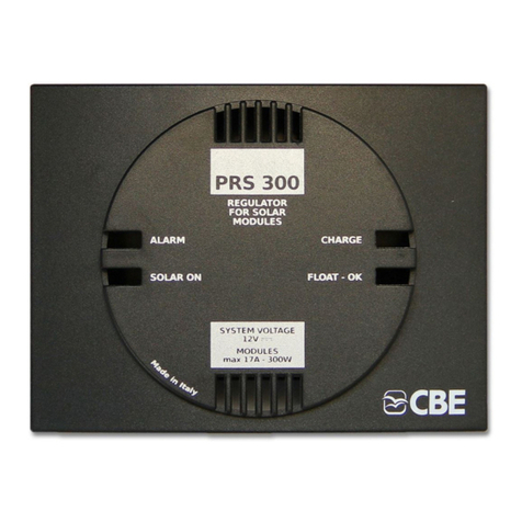
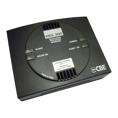
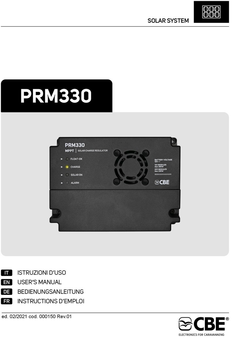
CBE PRM350 User manual

SOLAR SYSTEM
IT
DE
EN
FR
PRM350
ISTRUZIONI D’USO
USER’S MANUAL
BEDIENUNGSANLEITUNG
INSTRUCTIONS D’EMPLOI
ed. 09/2022 cod. 000150A Rev.00


3
IT
EN
Norme di utilizzo e installazione 9
REGOLATORE SOLARE PRM350 7
Legenda 8
Informazioni generali 7
Collegamenti 8
Avvertenze 4
Esempi collegamenti moduli fotovoltaici 10
Caratteristiche tecniche 12
Connections 14
Legend 14
Operating 15 instructions and installation
Warnings 4
PRM3 0 CHARGE REGULATOR5 SOLAR 13
Overview 13
Examples of photovoltaic module connections 16
Technical data 18

4
DE
FR
Technische Daten 24
PRM350 SOLAR ELAD REGLER 19
A 19llgemeine informationen
Hinweise 5
Z 20eichenerklärung
Beispiel für die Anschlüsse der Photovoltaik-Module 22
A 20nschlüsse
V I 21erwendungs- und nstallationsnormen
Mises en garde 5
REGULATEUR DE CHARGE PRM350 25
Informations générales 25
L 26égende
B 26ranchements
N 27ormes d'emploi et d'installation
C 30aractéristiques
Exemples branchements modules photovoltaïques 28

5
> Queste istruzioni contengono importanti informazioni sulla corretta installazione e
funzionamento del regolatore solare. Leggere accuratamente l’intero manuale prima di
procedere all’utilizzo.
> Le batterie esaurite devono essere smaltite attenendosi alle norme vigenti sulla tutela
dell’ambiente.
> Non ricaricare batterie non ricaricabili ." "
> L'installazione di questo apparecchio deve essere eseguita solamente da personale
tecnico specializzato.
> L’apparecchio può essere utilizzato da bambini di età non inferiore a 8 anni e da persone
con ridotte capacità fisiche, sensoriali o mentali, o prive di esperienza o della necessaria
conoscenza, purché sotto sorveglianza oppure dopo che le stesse abbiano ricevuto
istruzioni relative all’uso sicuro dell’apparecchio e alla comprensione dei pericoli ad esso
inerenti. I bambini non devono giocare con l’apparecchio.
> In caso di un utilizzo improprio dell'apparecchiatura, ne decade la garanzia ed il
produttore declina ogni responsabilità per danni a cose o persone.
ATTENZIONE:
IT
EN
> Exhausted batteries shall be disposed of according to the environmental protection
regulations in force.
> Do not use not rechargeable" batteries.with "
> The installation of this device must be carried out by specialist technicians.
ATTENTION:
> These instructions contain important information on correct installation and operation of
the solar regulator. Read the entire manual carefully before proceeding with use.
> In case of solar regulator misuse, the guarantee becomes invalid and the manufacturer
declines all responsibility for damages to people and property.
> This appliance can be used by children aged 8 years and with reduced
physical, sensory or mental capabilities or lack of experience knowledge
nstruct concerning use of
the appliance in a safe way and understand the hazards involved. Children shall
not play with the appliance.
or more people
or , only
provided they are being supervised or they have been i ed the
that they
AVVERTENZE
WARNINGS

6
DE
FR
> " icht aufladbare" Batterien aufladen.Keine n wieder
> Die erschöpften Batterien müssen unter Einhaltung der geltenden Umweltschutznormen
entsorgt werden.
> Einbau von diesem Gerät darf nur vom einem Fachmann durchgeführt werden.
> Im Falle vom Mißverbrauch verwirkt man die Garantie und haftet der Hersteller für keine
Sach- oder Personenschaden
.
> Das Gerät kann von Kindern über 8 Jahren und von Personen mit eingeschränkten
physischen, sensorischen oder geistigen Fähigkeiten oder mangelnde
benutzt werden, beaufsichtigt werden oder über die sichere
Verwendung des Geräts aufgeklärt und sie die damit verbundenen Gefahren
verstanden haben. Kinder dürfen mit dem Gerät nicht spielen
r Erfahrung
vorausgesetzt, dass sie sie
wurden
.
ACHTUNG:
> Diese Anleitungen enthalten wichtige Informationen zur korrekten Installation und
Funktion des Solarreglers. Vor der Installation muss man die gesamte
Bedienungsanleitung gelesen haben.
> Ces instructions contiennent des informations importantes sur l'installation correcte et
le fonctionnement du régulateur solaire. Lire soigneusement tout le manuel avant de
procéder à l'utilisation. .
> L'appareil peut être utilisé par des enfants si ces derniers sont âgés de 8 ans et plus et par
des personnes ayant des capacités physiques, sensorielles, mentales réduites ou
encore par des personnes dépourvues de la moindre expérience ou des connaissances
nécessaires sous réserve que ces derniers soient assistés ou qu'ils aient reçu toutes les
instructions pour une utilisation en toute sécurité de l'appareil et qu'ils aient pris
connaissance des risques inhérents audit appareil. Les enfants ne doivent pas jouer avec
l'appareil.
> L'installation de cet appareil doit être uniquement réalisée par un technicien spécialisé.
> Toute utilisation abusive de l'appareil entraînera la déchéance de la garantie et le
fabricant décline toute responsabilité quant aux dégâts causés à des choses ou à des
personnes
.
ATTENTION:
> Les batteries à plat doivent être éliminées conformément aux normes en vigueur en
matière de respect de l'environnement.
> Ne pas recharger des batteries non rechargeables ." "
HINWEISE
MISES EN GARDE

7
un errato settaggio della linea di carica può danneggiare la batteria stessa!
Selettore in posizione “A”
Max 14,1V
Max 14,4V
Max 14,7V
1h
4h
2h
13,5V
13,8V
13,8V
Selettore in posizione “B”
Selettore in posizione “C”
La posizione del selettore deve essere impostata
in funzione delle tensioni di carica più adatte al
tipo di batteria installata.
Nella maggior parte dei casi il selettore può essere
impostato in posizione per batterie al piombo-
liquido, in posizione per batterie al piombo-gel, in
posizione per batterie AGM
«A»
«B»
«C» «Li» e in posizione
per le batterie al litio.
1 2 3
Max 14,6V max 1h 13,8V
Selettore in posizione “Li”
Soglia limite
Linea «A» Linea «B» Linea «C» Linea «Li»
3
2
1
3
2
1
3
2
1
3
2
1
INFORMAZIONI GENERALI
Dispone di un sistema MPPT (Maximum Power Point
Tracker) che gli consente di prelevare in ogni
situazione la massima potenza erogabile dal modulo
fotovoltaico.
Il regolatore di carica PRM350 è in grado di caricare
batterie al piombo (liquido, gel e AGM) e Litio a 12V
in modo automatico controllando e limitando
l’energia fornita dai moduli fotovoltaici collegati.
Il PRM350 è adatto per il funzionamento con moduli
fotovoltaici da 32 a 72 celle fino ad una potenza
massima di 350W.
Per una resa ottimale del dispositivo si consiglia il
collegamento di moduli fotovoltaici con un numero di
celle superiore a 36, indipendentemente dalla
tipologia di installazione scelta (vedi paragrafo
"COLLEGAMENTI").
Fase 2: Absorption - Completamento della carica
della batteria con tensione di fine carica
costante per il tempo definito dalla linea di
carica con progressiva riduzione della cor-
rente.
Fase 1: Bulk - carica della batteria con la massima
corrente fino al raggiungimento della
tensione di fine carica.
Sistema di ricarica automatico a 3 fasi
NB: Il fine carica è raggiunto solo se la
batteria è efficiente.
Fase 3: Float - Carica di mantenimento a tensione
costante. Un elevato assorbimento dalla
batteria comporta la ripartenza dalla fase
Bulk.
REGOLATORE SOLARE “PRM350”
IT
SELETTORE TIPO BATTERIA COLLEGATA

8
LEGENDA
COLLEGAMENTI
1) Led verde FLOAT-OK: indica la fase di mante-
nimento della carica a tensione costante.
2) Led giallo CHARGE: indica che i moduli foto-
voltaici stanno caricando la batteria (con carica
> 0,1A).
3) Led bianco SOLAR ON: indica che il regola-
tore è acceso (in assenza di luce solare il
regolatore si spegne automaticamente).
5) Ventola di raffreddamento: con regolazione
automatica variabile.
4) Led rosso ALARM: indica l'eventuale inver-
sione di polarità (errato collegamento) dei
moduli fotovoltaici e/o della batteria servizi.
1) /
2) Uscita segnale solare (12V - max 50 mA)
3) /
4) /
SEGNALE SOLARE (solo con sistemi CBE)
6)
Collegamento nodi CL-BUS.
COLLEGAMENTO CL-BUS
8)
Connettore per collegamento al pannello test CBE modello PT742.
COLLEGAMENTO PT742
7)
15
2
3
4
6
7 8 9 10
11
IT

9
Sensore di temperatura da della
batteria e dove non possa essere influenzato da altre fonti di calore.
(mod."CTCB" L=3m) posizionare in prossimità
Se collegato, modifica i valori di tensione di carica in funzione della temperatura
rilevata.
COLLEGAMENTO (optional)SENSORE TEMPERATURA BATTERIA
COLLEGAMENTI BATTERIA/ MODULI FOTOVOLTAICI
SELETTORE TIPO BATTERIA COLLEGATA
9)
11)
10)
- Installare il regolatore in un apposito vano,
asciutto ed aerato; garantire una distanza minima
di 200mm dalla parte frontale e di 20mm dai lati
dell'apparecchio alle parti circostanti il vano.
- Si consiglia di tenere separato il cablaggio dei
moduli fotovoltaici dai cablaggi antenna
radio/TV/SAT, seguendo percorsi differenti.
- Fissare l’apparecchio con delle viti su una
superficie piana utilizzando i 4 fori presenti sulla
base.
- La connessione ad altre apparecchiature che
potrebbero danneggiarne il normale funziona-
mento ne fa decadere la garanzia.
- Il regolatore non è assolutamente adatto
all'uso in ambienti esterni.
- Il PRM350 non é adatto per la carica di bat-
terie a nichel/cadmio o altri tipi di batterie
ricaricabili o non ricaricabili non riportate in questo
manuale.
- Non ostruire le prese d'aria della ventola poste
sul coperchio.
- Proteggere i cavi da ogni possibile danneggia-
mento.
- Collegamento alla batteria: utilizzare cavi di
adeguata sezione. Sezioni consigliate:
- Collegare solo batterie 12V (6 celle) al piombo
ricaricabili (con capacità >40Ah).
- L' apparecchio genera calore durante il suo
normale funzionamento. Assicurarsi che l'instal-
lazione di eventuali altre apparecchiature nelle
immediate vicinanze del regolatore non compro-
metta la normale circolazione di aria e non ne
impedisca il necessario raffreddamento.
- 6 mm² (cavi di lunghezza inferiore a 5m)
- La batteria al Pb-Acido deve essere posizionata in
un luogo ben ventilato.
- Collegare solo batterie al litio specifiche per il
settore camper.
- Proteggere la linea 12V batteria con un fusibile
adeguato posto nelle vicinanze della batteria
stessa.
- 10 mm² (cavi di lunghezza superiore a 5m)
NORME DI UTILIZZO E INSTALLAZIONE
Fig.1 - DIMENSIONI (mm):
6.3
type Faston maschio tipo 6.3 per il collegamento della batteria e dei moduli
fotovoltaici.
140
48
150
IT
3
2
1

10
ESEMPI COLLEGAMENTI MODULI FOTOVOLTAICI
12V
12V
ESEMPIO 1
12V
12V
Connessione di un singolo modulo
fotovoltaico:
IT
A
N° CELLE
MODULO
“A” ≤ 40
“A” > 40
POTENZA
APPLICATA
max 175W
max 350W
12V
12V
12V
12V
Connessione di un singolo modulo
fotovoltaico:
ESEMPIO 2
A
N° CELLE
MODULO
“A” ≤ 40
POTENZA
APPLICATA
max 300W

11
12V
12V
Connessione in serie di 2 moduli
fotovoltaici:
ESEMPIO 4
IT
Connessione in parallelo di 2 moduli
fotovoltaici:
12V
12V
ESEMPIO 3
A B
“A”e“B” ≤ 40
“A”e“B” > 40
“A”+“B” max 300W *
“A”+“B” max 350W
* Sul singolo ingresso A e B non collegare
moduli fotovoltaici con potenza superiore a
175W.
“ ” “ ”
N° CELLE
MODULO POTENZA APPLICATA
(TOTALE)
N° CELLE
“A”+“B” ≤ 72
POTENZA (TOTALE)
“A”+“B” max 350W
“A”+“B” > 72 Non possibile
A B

12
CARATTERISTICHE TECNICHE
DATI TECNICI DI INGRESSO
Potenza massima
41÷72
Numero di celle
350W
DATI TECNICI DI USCITA
Tensione nominale
Linea di carica
Protezione corto circuito e
inversione di polarità
Protezione termica
Segnale ricarica solare
IUoU
Sì
12V ; 50 mA
12V
4 posizioni (A - B - C - Li)
Selettore di linea di carica
Sì
DATI TECNICI GENERALI
Temperatura ambiente
> 95%
250g
-10 a 50 + °C
Rendimento
Peso
* In assenza di sole il regolatore si spegne completamente.
Numero ingressi 2
Autoconsumo 0A*
Controllo MPPT Sì
150 x 110 x 48 (W x D x H in mm)
Dimensioni
Accessori Pannello test PT742
Autospegnimento In assenza di luce solare
Ventilazione Regolazione automatica variabile
IT
32÷40
300W

13
Selector on position “A”
Max 14,1V
Max 14,4V
Max 14,7V
1h
4h
2h
13,5V
13,8V
13,8V
Selector on position “B”
Selector on position “C”
The position of the selector must be set according
to the ingmost suitable charg voltages for the
type of battery installed.
for led- batteries, position for le d-gel
batteries position for AGM batteries
acid on a« »B
, on and on
position for lithium batteries.
« »C
«Li»
I onn most cases, the selector can be set position A« »
1 2 3
Max 14,6V max 1h 13,8V
Selector on position “Li”
Soglia limite
Line «A» Line «B» Line «C» Line «Li»
OVERVIEW
Note: of- the end- charge voltage is reached
only if the battery is efficient.
Phase 2: -Absorption battery charging at costant
of-
,
until the charging is
completed.
end- charge voltage for the time defined
by the charging line with a progressive
current reduction
Phase 1: battery charging with maximum
current until the end- charge voltage is
reached.
Bulk -
of-
3 phase automatic charging system
Phase 3: -Float Maintenance charg at constant
voltage. igh lead to phase
starting again.
ing
A h load s Bulk
“PRM3 0” 5 SOLAR CHARGE REGULATOR
EN
The PRM3 0 charge regulator can charge lead
(liquid, gel and AGM) and lithium 12V batteries
5 solar
automatically c and limiting the energy
supplied by the connected photovoltaic modules.
ontrolling
It a MPPT (Maximum Power Point Tracker)
system that allows picking in every situation of the
maximum power supplied by the photovoltaic
module.
features
The PRM3 0 is suitable for operation with 32 to 72-
cell photovoltaic modules up to a maximum power of
3 0W.
5
5
For optimal performance, you are advised to connect
the photovoltaic modules with a number of cells over
36, independent of the type of installation chosen (see
the “CONNECTIONS” paragraph).
CHARGE LINE SELECTOR.
3
2
1
3
2
1
3
2
1
3
2
1

14
LEGEND
CONNECTIONS
1) FLOAT-OK indicates the charge
maintenance stage at constant voltage .
Green led :
a
2) CHARGEYellow led : indicates that
photovoltaic modules are charging the battery
( >0.1 A).
the
with charge
3) SOLAR ON indicates that the
regulator is on (without sunlight, the regulator
turns off automatically).
White led :
4) ALARMRed led : indicates
(wrong connection) of photovoltaic modules
and/or leisure battery.
a reverse polarity
the
the
5) Cooling fan: with variable automatic adjust
ment.
-
2) Solar signal output (12V - max 50 mA)
1) /
3) /
4) /
SOLAR SIGNAL (with CBE systems only)
6)
CL-BUS nodes connection.
CL-BUS CONNECTION
8)
Connector for connection to the CBE test panel model PT 2.74
PT 2 CONNECTION74
7)
EN
15
2
3
4
6
7 8 9 10
11

15
When is adapted according to the temperature
measured by the sensor.
connected, the charging voltage
Temperature sensor (mod. “C , where
it cannot be affected by other heat sources
TCB” L=3m) to be placed close to the battery
.
CONNECTION BATTERY TEMPERATURE SENSOR (optional)
9)
11)
10)
- Install the regulator in an appropriate dry and
ventilated housing; make sure there is a minimum
distance of mm from the front and mm from
the sides to the surrounding
surfaces.
200 20
of the device
- The regulator is not suitable for external use.
- Solar System cables should be placed far away
from the cables for Radio/TV/SAT antenna .s
- Connection to other equipment which can dama
ge correct operation may result in warranty
void.
-
its
- Do not cover air intakes on the lid.the
- Fasten the equipment with the screws on a flat
surface using the 4 holes on the base.
- he PR egulator is not suitable for the
charging of nickel/cadmium batteries, other kinds
of rechargeable or non rechargeable batteries not
outlined in this manual.
T M350 r
- Lead-acid batteries shall be positioned in a well
ventilated place.
- 10 mm (cable over 5m long)²
- Battery connection: use cables with adequate
section. Recommended sections:
- The produces heat during normal
operation. Make sure that the installation of other
equipment near the instrument does not hamper
the correct air flow and prevent the necessary
instrument cooling.
device its
- Protect the cable from any possible damage. s
- Protect the 12V battery line using a suitable fuse
to be placed close to the battery.
- Only connect specific lithium batteries for the
sector.
RV
- 6 mm (cable under 5m long)²
- nnect only 12V rechargeable lead
batteries (capacity >40Ah).
Co (6 cells)
OPERATING INSTRUCTIONS AND INSTALLATION
Pic. 1 - DIMENSIONS (mm):
6.3 Male faston type 6.3 for connection of the battery and the photovoltaic modules.
140
48
150
EN
CHARGE LINE SELECTOR.
BATTERY/ PHOTOVOLTAIC MODULES CONNECTION
3
2
1

16
EN
EXAMPLES OF PHOTOVOLTAIC MODULE CONNECTIONS
12V
12V
EX MPLE 1A
12V
12V
Connection of a single photovoltaic module:
A
NO. MODULE
CELLS
“A” ≤ 40
“A” > 40
POWER
APPLIED
max 175W
max 350W
12V
12V
12V
12V
Connection of a single photovoltaic module:
EX MPLE 2A
A
NO. MODULE
CELLS
“A” ≤ 40
POWER
APPLIED
max 300W

17
EN
12V
12V
Connection in series of 2 photovoltaic
modules:
EX MPLE 4A
Parallel connection of 2 photovoltaic
modules:
12V
12V
EX MPLE 3A
A B
“A” “B” ≤ 40 and
“A” “B” > 40 and
“A”+“B” max 300W *
“A”+“B” max 350W
* On input "A” and "B”, do not
connect photovoltaic modules with power over
1 W.
each single
75
NO. MODULE
CELLS POWER APPLIED
(TOTAL)
N ° CELLS
“A”+“B” ≤ 72
POWER (TOTAL)
“A”+“B” max 350W
“A”+“B” > 72 Not possible
BA

18
SPECIFICATIONS
INPUT TECHNICAL DATA
Potenza massima
41÷72
Numero di celle
350W
GENERAL TECHNICAL DATA
Room temperature
> 95%
250g
-10 a 50 + °C
Efficiency
Weight
* Without sunlight, the regulator turns off completely
Number inputs 2
Self-consumption 0A*
MPPT control Yes
150 x 110 x 48 (W x D x H in mm)
Dimensions
Accessories P 2 test panelT74
Auto turn-off If sunlight is not present
Ventilation Gradual automatic regulation
32÷40
300W
EN
OUTPUT TECHNICAL DATA
Nominal voltage
Charg lineing
Short circuit and polarity
ioninversion protect
Thermal protection
Solar charge signal
IUoU
Yes
12V ; 50 mA
12V
4 (A - B - C - Li)positions
Charg line selectoring
Yes

19
Wahlschalter auf “A”
Max 14,1V
Max 14,4V
Max 14,7V
1h
4h
2h
13,5V
13,8V
13,8V
Wahlschalter auf “B”
Wahlschalter auf “C”
Die Stellung des Wahlschalters muss gemäß der
für die installierte Batterie passenden Ladespan
nung eingestellt werden.
-
In den meisten Fällen kann der Wahlschalter auf
bei Blei-Säure-Batterien, auf bei Blei-Gel
Batterien auf bei AGM Batterien eingestellt
werden
« »A
« »B -
,« »C
und auf für Lithium-Batterien. «Li»
1 2 3
Max 14,6V max 1h 13,8V
Wahlschalter auf “Li”
Soglia limite
Linie «A» Linie «B» Linie «C» Linie «Li»
ALLGEMEINE INFORMATIONEN
Phase 1:Bulk - Aufladen der Batterie mit
Strom bis zum Erreichen der Ladeschluss
spannung
maximalem
-
.
Automatisches Aufladesystem mit Phasen
Bemerkung: Die Ladeschlussspannung
wird nur erreicht, wenn die Batterie richtig
funktioniert.
Phase 2: Absorption Fertigstellung der Batterie
aufladung mit konstanter Ladeschluss
spannung über einen von der Ladekennlinie
bestimmten Zeitraum, mit einer progres
siven Stromreduzierung.
--
-
-
Phase 3: Float ei konstanter Spannung. Ein hoher
Stromverbrauch führt zum Neustart der
Phase .
-B
Bulk
“PRM350” SOLAR E LAD REGLER
DE
Der Laderegler PRM3 0 kann Blei- (Flüssigkeit, Gel
und AGM) und Lithium 12V Batterien automatisch
laden, indem er die von den angeschlossenen
Photovoltaik-Modulen gelieferte Energie steuert und
begrenzt.
5
Er verfügt über ein MPPT-System (Maximum Power
Point Tracker), mit dem er in jeder Situation die vom
Photovoltaik-Modul maximal lieferbare Leistung
entnehmen kann.
Zur Garantie der optimalen Leistung der Vorrichtung
empfehlen wir den Anschluss von Photovoltaik-
Modulen mit mehr als 36 Zellen, unabhängig von der
Art der gewählten Installation (siehe Abschnitt
"ANSCHLÜSSE").
Der PRM3 0 ist für die Funktion mit Photovoltaik-
Modulen von 32 bis 72 Zellen, mit einer maximalen
Leistung von 3 0W geeignet.
5
5
WAHLSCHALTER DER LADE LINIEKENN
3
2
1
3
2
1
3
2
1
3
2
1

20
ZEICHENERKLÄRUNG
ANSCHLÜSSE
1) G FLOAT-OK Sie zeigt die rüne Leuchtdiode :
Erhaltungsladung bei konstanter Spannung an
2) G CHARGE:elbe Leuchtdiode
(mit aufladen > 0,1A).
Sie zeigt an,
dass die fotovoltaischen Module dabei sind, die
Batterie aufzuladen
3) SOLAR ON Sie zeigt an,
dass der Laderegler eingeschaltet ist (bei
Abwesenheit von Sonnenlicht schaltet sich der
Regler automatisch aus).
Weiße Leuchtdiode :
5) Kühlgebläse: Mit variabler automatischer
Einstellung.
4) Rote Leuchtdiode ALARM: Sie zeigt die
eventuelle (falsche Verbindung) der
fotovoltaischen Module und/oder der Service
batterie an.
Verpolung
-
1) /
2) Solarsignalausgang (12V - max 50 mA)
3) /
4) /
SOLARSIGNAL (nur mit CBE Systemen)
6)
Anschluss CL-BUS Knoten.
ANSCHLUSS CL-BUS
8)
Stecker zum Anschluss an das CBE Test-Bedienfeld Modell PT 2.74
ANSCHLUSS PT 274
7)
DE
15
2
3
4
6
7 8 9 10
11
Table of contents
Languages:
Other CBE Controllers manuals
Popular Controllers manuals by other brands

Rain Bird
Rain Bird EZ1-D Programming instructions

AAON
AAON V12100 MHGRV-X Field Technical Guide

Exlar
Exlar Curtiss-Wright Tritex TTX Series Installation & service instructions

Pivot
Pivot 3-drive PRO user manual

Compaq Storageworks
Compaq Storageworks HSG80 quick start guide

Spring
Spring V11 quick start guide