CDI Meters 5250 User manual

cdimeters
CDI Meters, Inc. support@cdimeters.com 866-885-2462
www.cdimeters.com
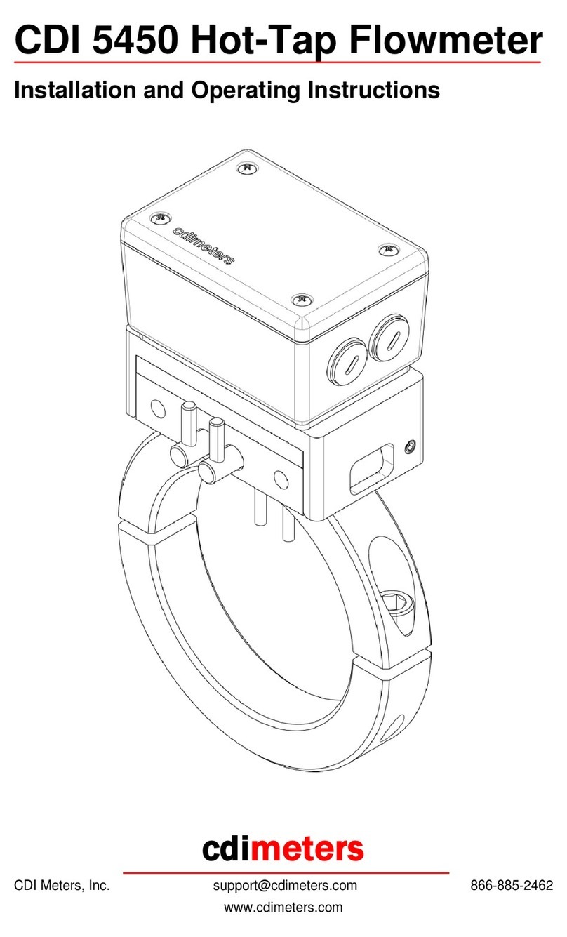
CDI 5250 Hot-Tap Flowmeter
Installation and Operating Instructions

©2019 CDI Meters, Inc. 10.19
Safety Precautions
Installation of the meter requires two hands, and missteps could cause a release
of air that would startle the installer. Consequently, the work should be done from
a lift or staging, and fall protection must be provided where appropriate.
Opening either valve at the wrong moment or withdrawing the drill without closing
the corresponding valve would cause air containing sharp chips to blow out at
high velocity. Consequently
Gloves and face protection must be worn.
The installer should practice opening and closing the valves and
withdrawing the drill several times before drilling the holes.
Normally, the chips formed by the drilling operation are small. If long chips are
formed, the installer should back out the drill frequently to clear the chips so that
they will not prevent the valves from being closed.
Limitations and Cautions
CDI 5250 flowmeters are not for use in hazardous areas or on pipes containing
gasses other than air or nitrogen. They must be installed in a pressurized pipe to
ensure all chips are cleared. They are not for use in control or safety
applications or designed for installation where pressure exceeds 130 psig (9
barg). The temperature compensation of the meters is suitable for use from 20
to 120°F (-7 to 49°C).
Locating the Meter
For accurate and reliable readings, the meters must be installed with adequate
straight pipe upstream, and, in compressed-air applications, they must be
installed downstream of a dryer.
Select a location with a straight run of pipe upstream equal to at least twenty
times the pipe diameter. If the meter is downstream of something that could
distort or concentrate the flow, such as a sweep elbow, a partially-closed valve,
an increase in pipe size or a hose, the run of pipe should be as long as possible;
thirty times the diameter at a minimum. Five diameters of straight downstream
piping is sufficient, unless the meter is immediately upstream of something that
would restrict the flow, such as a valve. If possible, locate and orient the meter
for good visibility from the plant floor.
The meters may, when necessary, be installed outdoors. For best visibility, avoid
direct sunlight.

©2019 CDI Meters, Inc. 10.19
Preparing for Installation
When the holes are drilled, metal shavings will enter the pipe. Make sure that
filters or other provisions are present downstream to prevent shavings from
damaging equipment or product or being blown out and causing injury.
Prepare the meter for the direction of flow. The flow arrow on the meter must be
oriented to match the direction of flow in the pipe. If doing so will cause the
display to be upside-down, remove the cover of the meter, lift out the display,
rotate both 180° and re-install.
Apply the “Holes in Pipe” decal so that it will be hidden when the meter is in place
but will be revealed when it is removed.
Installing the Meter
Installation of the CDI 5250 Hot Tap Flowmeter should be done by an
experienced mechanic. As a precaution, hearing, face, and hand protection
should be worn at all times. If done properly, the sound of the drill will be the
loudest part of the installation.

©2019 CDI Meters, Inc. 10.19
Step 1
a. Mount the base assembly on the pipe and
tighten the cap screws evenly. The torque
should be sufficient to seal the gasket but
not so great that it will crush the gasket, or
distort or over-stress the pipe.
b. Place the drill guide over the exposed
socket head cap screws, sliding fully to the
other side, and tighten. Orient the drill guide
so that the muffler is horizontal or pointing
down.
c. Open the corresponding valve.
d. Install the 5/32” drill bit into the drill’s chuck.
Insert the bit into the drill guide and base
until the tip makes contact with the pipe.
The distance between the chuck and the top
of the drill guide must exceed the thickness
of the pipe’s wall. Readjust if necessary.
Step 2
a. Without applying too much force, begin
drilling the hole. Occasionally back the drill
bit off of the pipe to help dissipate heat and
clear the chips.
b. Once you have broken through the first wall
of the pipe, and being careful not to drill into
the far wall, run the drill bit up and down
through the hole to ensure clean edges.
With the drill bit still spinning, extract it so
one to two inches of it is exposed, being
careful not to completely remove the bit or
expose the flute. Hold it there for a few
seconds to give time for all chips to bypass
the drill bit and collect within the muffler.
c. Carefully remove one hand from the drill
and apply light pressure to the
corresponding valve handle as if you were
closing it. While the bit is spinning, begin
extracting the drill bit slowly. The pressure
applied to the valve handle will help indicate when the drill bit has cleared.
When this happens, rotate the handle 90° to its closed position. It is now
safe to completely remove the drill bit. At this stage a slight hiss may be
present through the drill guide.

©2019 CDI Meters, Inc. 10.19
d. Loosen, but do not remove, the screws holding down the drill guide. Slide
the drill guide off those screws and repeat step 1b for the other set of
screws.
e. Open the corresponding valve.
f. Repeat steps 2a through 2c.
Step 3
a. Loosen the screws holding down the
drill guide, remove it, and empty the
chips from the muffler. Wipe away any
chips that may have fallen on top of
the base. Place the slider plate over
the screws with the side containing the
O-rings facing the base. Slide it into
position so the alignment pins are in
place and it sits flat against the base.
Tighten the screws so that the slider
plate is firmly mounted to the base.
b. With the flow arrow in the correct
direction, insert the probes into the two
holes of the slider plate. Expect some
resistance as the probes make their
way through the O-rings. Continue to
push in until the probes make contact
with the closed valves. At this point any leakage noted in step 2c should go
away.
Step 4
a. With one hand firmly holding the top
assembly, use the other to rotate each
valve 90° to its open position. Push
the top assembly into place until you
hear an audible ‘click’, letting you know
the two latches are now firmly in place
and it is safe to let go. You can expect
approximately five pounds of force at
the meter’s maximum pressure rating.
b. To complete the installation, there are
two safety screws that will need to be
placed in the side of the top bracket
next to each latch. Screw both in until
they bottom out.

©2019 CDI Meters, Inc. 10.19
Wiring the Meter
Wiring must be in accordance with applicable codes and standards. In areas
where electrical interference may be present, signal wiring should be shielded
with the shield grounded remote from the meter. Signal cables must not be run in
conduit or cable trays shared with power wiring. The main terminal block inside
the meter is accessed by removing the cover and lifting out the display circuit
board.
POWER
Either use the dc wall-plug supply furnished with the meter, or connect the
terminals marked “24V dc” to a distributed dc power supply and seal the unused
power opening with the plastic plug provided. The meter will draw a maximum of
250 mA. Unlike earlier 5200 and 5400 meters, the Rev. 3 meters do not connect
the dc- terminal to the pipe on which they are mounted. Please note that 18 Volt
dc supplies furnished with some earlier CDI flowmeters do not provide the
voltage required for Rev. 3 meters.
REMOTE DISPLAY
If you are using the summing remote display (SRD), connect the three terminals
marked “display” to the corresponding terminals in the remote display. The meter
may be powered from the remote display if the cable is 22 gauge or heavier and
the distance is no greater than 200 feet.
MILLIAMP OUTPUT
The 4 - 20 milliamp output is optically isolated within the meter and it is provided
with a factory-installed jumper which allows it to source a milliamp signal
powered from the meter. The resistance of the loop connected to the output
should not exceed 600 Ohms.

©2019 CDI Meters, Inc. 10.19
PULSE OUTPUT
The pulse output is open-collector, that is, a transistor switch to the meter’s
negative supply. To use it, connect it to the input of the receiving device; also
connect that input through a 10K Ohm resistor to a suitable positive supply and
connect the negative supply of the receiving device to the negative supply of the
meter. If an isolated relay contact is required, install the CDI 5200-IPO isolated
pulse output and wire it to the receiving device.
SERIAL COMMUNICATION OPTION
The RS-485 signal used with the Serial Communication option is wired to the
Serial Communication display board. The two threaded openings in the meter
enclosure permit the signal to be wired from meter to meter without external
splices. Please refer to the data sheet for the Serial Communication options.

©2019 CDI Meters, Inc. 10.19
Using the Outputs
The milliamp output is scaled so that four milliamps corresponds to zero flow and
20 milliamps corresponds to the range of the meter indicated on the data sheet.
The meter will display the milliamp full-scale value for a few seconds on startup.
It will also display it if the button on the main (lower) circuit board is pressed
twice.
The pulse output generates a square wave signal, sending one pulse for each
cubic foot of air that passes through the meter. The LED blinks with the pulse
output. At zero flow it may be on or off. The pulse output can be configured as a
threshold output, and the scaling of both the pulse output and the milliamp output
can be changed, using the optional configuration cable.
Using the Display
Pressing a button indicated by a circle on the front of the meter cycles the display
through four display options: rate, daily usage, cumulative usage and units of
measure, the last indicated by a digit: (0) for scfm, (1) for m3/min and (2) for
m3/hr. The cumulative values are indicated in thousands of cubic feet or cubic
meters. Holding the button pressed in either of the cumulative modes (daily
usage or cumulative usage) will reset that value to zero. The display normally
defaults to the rate display, but this can be changed, as can the units of measure
and the decimal point location in the cumulative modes. Please refer to
information on configuring the display.
Maintenance
If oil or dirt accumulates on the probes, the meter will read inaccurately. For this
reason, we recommend cleaning the probes from time to time. To clean the
probes, wipe them with a cloth dampened with alcohol or a similar degreaser. It
may be found that the system is clean enough that cleaning is not needed.
Warranty
CDI warrants solely to the buyer that the Model 5250 Flowmeter shall be free from
defects in materials and workmanship, when given normal, proper and intended
usage, for three years from the date of purchase. During the warranty period, CDI will
repair or replace (at its option) any defective product at no cost to the buyer. The
foregoing warranty is in lieu of any other warranty, express or implied, written or oral
(including any warranty of merchantability or fitness for a particular purpose). CDI’s
liability arising out of the manufacture, sale or supplying of the flowmeter, whether
based on warranty, contract, tort or otherwise, shall not exceed the actual purchase
price paid by the buyer, and in no event shall CDI be liable to anyone for special,
incidental or consequential damages.
Table of contents
Other CDI Meters Measuring Instrument manuals

CDI Meters
CDI Meters CDI 25 Series User manual

CDI Meters
CDI Meters CDI 25 User manual

CDI Meters
CDI Meters CDI 5400 User manual

CDI Meters
CDI Meters CDI 5450 User manual

CDI Meters
CDI Meters 5400 User manual

CDI Meters
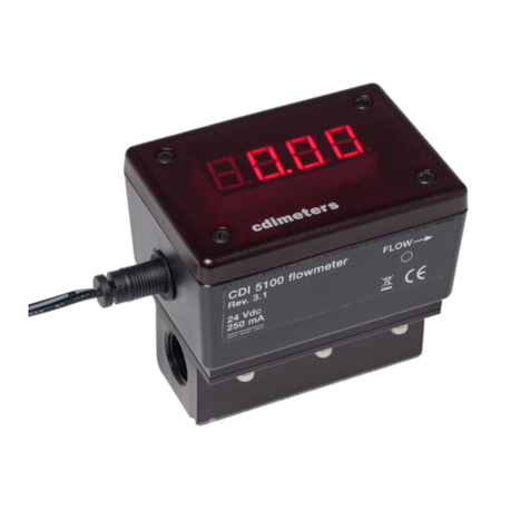
CDI Meters CDI 5100 User manual

CDI Meters
CDI Meters CDI 25 User manual

CDI Meters
CDI Meters CDI 5400 User manual
Popular Measuring Instrument manuals by other brands

Siemens
Siemens SITRANS F US Protocol manual

PRÜFTECHNIK
PRÜFTECHNIK VIBSCANNER 2 Getting started

Spirax Sarco
Spirax Sarco RIM10 Series Installation and maintenance instructions

Ankom
Ankom 2000 Operator's manual

PCE Instruments
PCE Instruments PCE-TG200 instruction manual

Polanik
Polanik WG15-SONIC instruction manual