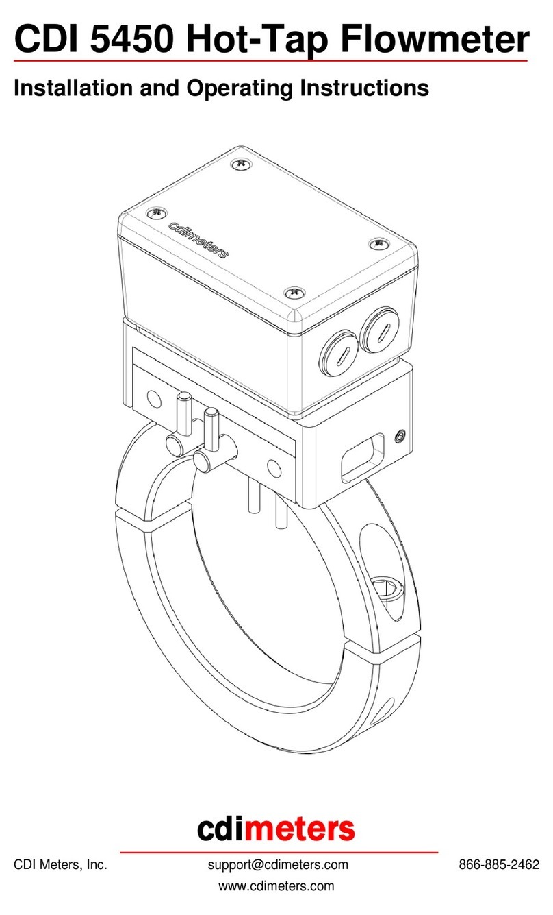
Installing the Meter
Make sure the probes are clean. If there is any oil or dirt on them, clean them
with alcohol or a similar degreaser. If the housing must be rotated to suit the
installation, loosen (do not remove) the two small cap screws in the plate
beneath the housing, rotate the housing, and tighten the screws. Insert the
probes into the holes in the pipe, with the flow arrow pointing in the direction of
flow. Tighten the screws carefully, alternating screws, so that the two sides of the
collar are pulled together evenly. If the LED display is upside down, remove the
cover of the meter, rotate it and the display panel 180 degrees, and reinstall the
cover. If the yellow caution label is not visible, apply the extra caution label from
the bag of parts in a visible location.
Wiring the Meter
POWER
Either use the 18-Volt dc wall-plug supply provided with the meter, or connect a
24-Volt dc supply to the DC- and DC+ terminals. The DC- terminal is connected
to the pipe on which the meter is mounted.
REMOTE DISPLAY
If you are using Summing Remote Display, connect the DC-, DC+ and display
terminals in the display to the corresponding terminals in the meter. The meter
may be powered from the remote display if the connecting cable is 22 gauge or
larger and the distance is no greater than 60 feet.
MILLIAMP OUTPUT
The mA- and mA+ terminals are optically isolated from the remainder of the
circuit and may be wired as part of an externally-powered loop. When this is
done, the jumper that is supplied with the meter must be removed. If you use an
external supply, be sure that it has sufficient voltage to overcome an 8.2 Volt
drop within the meter in addition to any other voltage drops in the loop. Powering
the milliamp circuit from an external supply does not provide power to the meter
itself. The meter must be powered from its wall-plug supply or a separate 24 Volt
dc supply.
Alternatively, the meter’s supply may be used to power the milliamp signal.
Leave the jumper in place from the DC+ terminal to mA+. Wire from the mA-
terminal to the positive side of the external receiver and from the negative side of
the external receiver to the DC- terminal. Power the meter from its wall-plug
supply or a 24V dc supply. Note that the DC- terminals are connected to the pipe
on which the meter is mounted.
©Copyright 2006 - 2010 CDI Meters, Inc. 07.10
PULSE OUTPUT
The pulse output is an open-drain output, that is, a transistor switch connected to
the meter’s negative supply. To use the output, connect it to an input of the
receiving device (usually a counter or PLC) and connect a pullup resistor from
that input to a positive supply suitable for the receiving device. Also connect the
negative supply terminal of the meter to the negative supply of the receiving
device. If an isolated relay contact is required, install the CDI 5200-IPO isolated
pulse output and wire it to the receiving device.
SERIAL COMMUNICATION OPTION
The RS-485 signal used with the Serial Communication option is wired to the
special Serial Communication display board. The two threaded openings in the
meter enclosure permit the signal to be wired from meter to meter without
external splices. Please refer to the data sheet for the Serial Communication
option.
Using the Outputs
The milliamp output is scaled so that four milliamps corresponds to zero flow and
20 milliamps corresponds to a flow rate that is above the calibrated range. The
flow rate that corresponds to 20 milliamps is displayed for a few seconds each
time the meter is powered up.
The pulse output generates a square wave signal, sending five pulses for each
cubic foot of air that passes through the meter. The LED blinks with the pulse
output. At zero flow it may be on or off.
Maintenance
If oil or dirt accumulates on the probes, the meter will read low. For this reason,
we recommend cleaning the probes from time to time. To clean the probes, wipe
them with a cloth dampened with alcohol or a similar degreaser. It may be found
that the system is clean enough that cleaning is not needed.

