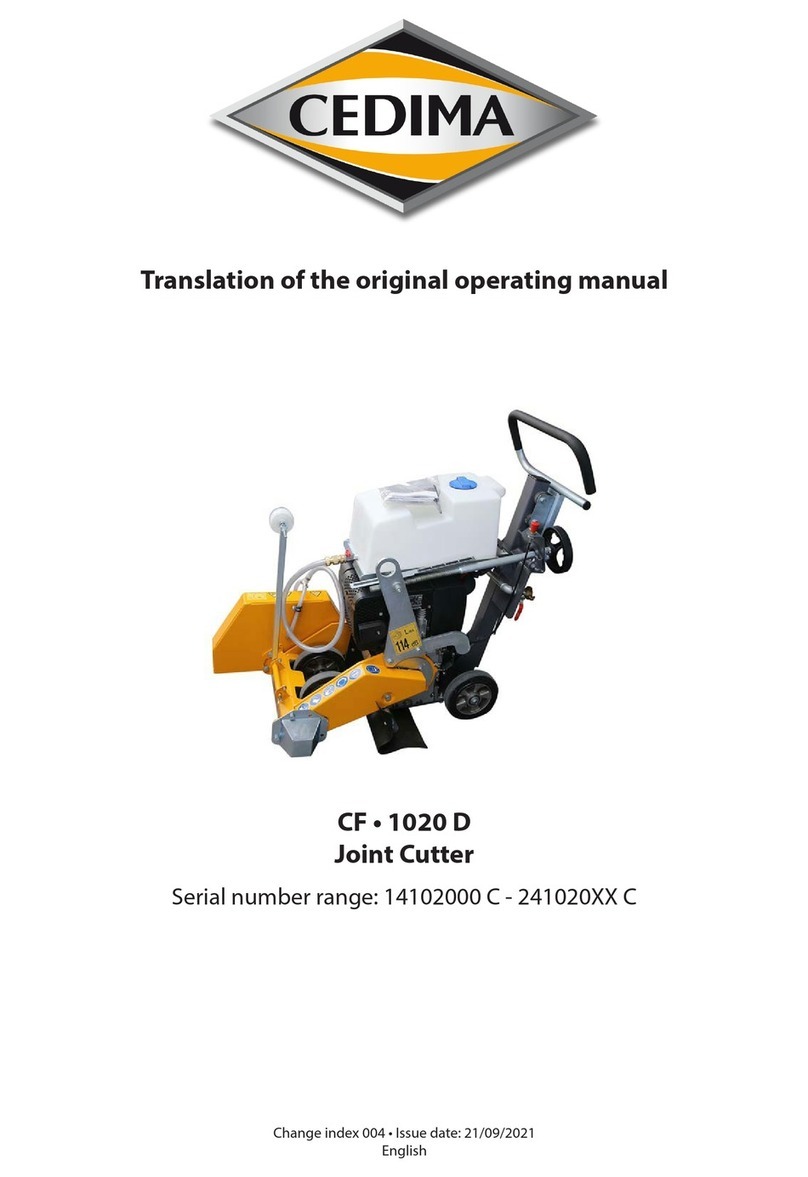
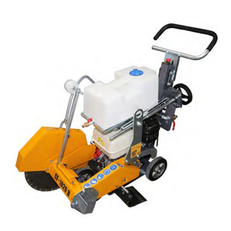
Cedima CF-2116 D Operating instructions

Operating manual
maintenance manual
and safety notes
CF•2116 D
Serial CF-2100
from 11/2006
•Joint cutters
• Diamond drilling
•Table saws
•Wall saws
•Wire saws
•Hydraulic units
•Special machinery
Change index 003 Issue date June 2013
Translation of the original operating manual

ENGLISH
• CEDIMA® • Technical Documentation • All rights reserved as per ISO 16016 • Subject to modications due to progressive development •
CEDIMA®
Diamantwerkzeug- und Maschinenbauges. mbH
Celle/Germany
© Copyright CEDIMA®– Technical Documentation
All rights reserved acc. to DIN ISO 16016. No part of this documentation may be reproduced,
adapted, stored in a retrieval system or transmitted in any form or by any means, electronic,
mechanical, photocopying, recording or otherwise, or translated into a foreign language without
the prior written consent other than permitted under copyright law.
Warranty
The information contained in this publication may change without prior notice.
CEDIMA
® exclusively assumes liability as required by law for these documents.
CEDIMA
® does not accept any liability for errors which may be contained in this operating
manual/spare parts list nor for any incidental or consequential loss or damage that may arise in
connection with the delivery, performance or use of the material beyond the legal requirements.
Trademark
The name
CEDIMA
® and the logo
is a registered trademark of
CEDIMA
®
Diamantwerkzeug- und Maschinenbauges. mbH

ENGLISH
• CEDIMA® • Technical Documentation • All rights reserved as per ISO 16016 • Subject to modications due to progressive development •
EC Declaration of conformity
Manufacturer:
CEDIMA® Diamantwerkzeug- und Maschinenbaugesellschaft mbH
Lärchenweg 3, D-29227 Celle
Compilation, storage of the technical data:
Technical documentation of the
CEDIMA® Diamantwerkzeug- und Maschinenbaugesellschaft mbH,
Siedemeierkamp 5, D-29227 Celle
Description of the machine:
Joint cutter CF•2116 D, article no. 30000051 (standard), 30000178 (green concrete)
Self-driving, hand-guided, in green concrete (FB) or standard design. Hydrostatic feed
drive. For wet cutting in asphalt and concrete as well as similar abrasive construction
materials with diamond saw blades up to 800 mm (standard) or 400 mm (FB = green
concrete) diameter with a max. saw blade clamping width of 20 mm. Cutting shaft drive via
V-belts by a 314,7 kW diesel engine. Max. cutting depth 300 mm (standard) or 100 mm
(FB) stepless adjustable via electro-hydraulic frame jack. Water supply via pressure water
connection or of a 35 l tank carried with the machine.
Measured sound power level: LWA = 110 dB (A)
Guaranteed sound power level: LWA(d) = 114 dB (A)
Method of evaluating the declaration of conformity: RL 2000 /14/EC, appendix V
Herewith we declare that based on the guideline 2006 / 42 / EC, Annex II 1.A dated
2006.05.17 (modications inclusive) of the European Parliament and Council
the joint cutter CF•2116 D beginning with year of construction 2006
complies with the following standards and guidelines:
EN ISO 12100-1, EN ISO 12100-2, EN 13862, EN ISO 14121-1, EN 60204-1, 2000/14/EC
In regard to dangers due to electricity, according to Annex I No. 1.5.1 of the Machinery
Directive 2006/42/EC, the protective aims of the Low Voltage Directive 2006/95/EC
(formerly 73/23/EEC) are met.
In regard to dangers due to radiation, according to Annex I No. 1.5.10 of the Machinery
Directive 2006/42/EC, the protective aims of the EMC Directive 2004/108/EC (formerly
89/336/EEC) are met.
This declaration of conformity immediately becomes invalid if changes are
incorporated to the machine which have not been approved by us!
Celle, 31. 08. 2010 B. Siemsen (managing director)

ENGLISH
• CEDIMA® • Technical Documentation • All rights reserved as per ISO 16016 • Subject to modications due to progressive development •
Preface
Thank you for choosing a CEDIMA® product.
This operating manual will help you to get to know the machine and to use it for applications it is
intended for.
This operating manual addresses Specialists and users/operators trained by Specialists.
The operating manual provides important information on how to use the machine safely, prop-
erly and economically. Following the instructions is necessary for your safety, for reducing repair
costs and downtimes and to maintain reliability and extend the useful life of the machine.
Read through this manual carefully before you start working with your new machine.
The manual must be kept close to the machine at all times.
The operating manual must be read and applied in practice by anyone who will be working with
or on or handling the machine E.G.:
– operation, including preparation of the machine, clearing of minor faults on site, disposal of
waste, care maintenance, disposal of process substances and auxiliary substances
– maintenance (inspection, repairs) and/or
– transport.
The operating manual are to be supplemented by any instructions contained in the regulations
of your country concerning accident prevention and environmental protection.
Besides the operating manual and local regulations on accident prevention that apply in the
user’s country and place of use, the user must observe general technical regulations such as
the regulations of trade associations on safety and proper working.
This operating manual provides full information as required for the proper use of the machine,
but should you feel the need to approach us with any queries, please do not hesitate to contact
one of our eld representatives, or CEDIMA® directly at:
CEDIMA® Diamantwerkzeug-
und Maschinenbauges. mbH
Lärchenweg 3 • 29227 Celle/Germany
Phone +49(0)5141/8854-0
Fax +49(0) 51 41/ 8 64 27
Internet: www.cedima.com
E-mail: info@cedima.com

ENGLISH
Contents of the operating manual
• CEDIMA® • Technical Documentation • All rights reserved as per ISO 16016 • Subject to modications due to progressive development •
Uniform statement of conformity
Preface
CHAPTER 1 General information on the product
CHAPTER 2 Technical data and accessories
CHAPTER 3 General safety instructions
CHAPTER 4 Installation and control elements
CHAPTER 5 Cutting operation
CHAPTER 6 Maintenance and care
CHAPTER 7 Transport and longer periods out of service/storage
CHAPTER 8 Trouble shooting, what if . . .?
CHAPTER 9 Circuit diagrams
CHAPTER 10 Appendix

ENGLISH
6
General information on the product
• CEDIMA® • Technical Documentation • All rights reserved as per ISO 16016 • Subject to modications due to progressive development •
The joint cutters of series CF-2100 are known for their
extremely simple operation, the gentle use of diamond
saw blades and their high daily output. The joint cutter
CF-2116 D of series CF-2100 is used as a separating
and deep cutting machine up to a cutting depth of
300 mm in asphalt and concrete, for the construction
and repair of roadways, roads, cycle ways, supply
ways, airelds and industrial plants. Their manoeuvra-
bility also makes the joint cutters of series CF-2100
indispensable on green concrete.
The arrangement of all components with the resulting
weight distribution provides optimum cutting pressure
on the diamond saw blade with simultaneous easier
handling when moving and setting up.
The joint cutters of series CF-2100 are characterised
by great reliability, maximum power utilisation, simple
handling and a high level of operating comfort. Drive
unit and speed of cutting shaft are designed to ensure
optimum conditions for cutting with CEDIMA® diamond
saw blades.
The saw blade of the CF-2116 D is driven by a modern,
powerful diesel motor via V-belts to the cutting shaft.
The saw blade can be mounted on the right or left
side of the precisely manufactured cutting shaft with
a blade receptacle’s diameter of 25,4 mm. The blade
guard, also to be mounted right or left, is hinged in
front (g. 1.2) in order to enable cuts right up to the
wall. Feed is constantly carried out by means of a
hydrostatic, innitely adjustable feed gear.
A clearing of the feed gear also enables manual
movement of the joint cutter. The feed gear is
simultaneously used as a parking brake when the drive
motor is stopped.
The cutting depth adjustment up to a cutting depth of
300 mm is effected by an electro-hydraulic unit that can
precisely be operated by a control lever integrated in
the control panel. The lowering speed is pre-adjustable.
The cutting depth indicator is adjustable.
The cutting shaft can be lowered manually, without mo-
tor, via a valve (transport).
The adjustable front and rear pointers, mounted to the
machine frame, enable the operator to cut precisely
along a marked line.
The water for cooling the diamond saw blade is led via
pipes and nozzles in the blade guard to the saw blade.
This guarantees a complete wetting and the optimum
cooling of the diamond saw blade.
1.0 General information on the product
1.1 Description of the joint cutter CF-2116 D
modern, powerful diesel motor clearly arranged
control panel
height-
adjustable
push rods
blade drive via V-belts adjustable rear pointersaw blade receptacle
right/left
adjustable front pointer
hinged blade guard
water supply via blade guard
joint cutter CF-2116 D Fig. 1.1

ENGLISH
7
General information on the product
• CEDIMA® • Technical Documentation • All rights reserved as per ISO 16016 • Subject to modications due to progressive development •
The CF-2116 D can be operated with water supplied
under pressure or by means of a self-suctioning water
pump (out of a 35 l tank carried with the machine).
For cutting we recommend CEDIMA® diamond saw
blades that guarantee a protection of the joint cutter
due to their cutting performance and smooth running
and that are thus considered to be the most important
component of the entire cutting unit.
1.2 Features of the CF-2116 D
• Compact construction
• Motor speed adjustment via bowden cable.
• Double-sided blade receptacle (in turn)
• V-belt drive to cutting shaft (motor protection by slip-
ping clutch effect)
• Hydrostatic (hitchless) feed
• Removable 35 l water tank
• Alternative connection of water supplied under pres-
sure
• Adjustable cutting depth indicator
• Blade guard, cutting shaft cover and ange cover to
be used on both sides
• Hinged front blade guard to cut directly to the wall
• Multiply (innitely) adjustable push rods
• Adjustable front and rear pointers
• Hydraulic cutting depth adjustment and lifting of cut-
ting shaft with adjustable lowering speed
• Electro-hydraulic quick-lifting
• Electric starting device
• Electric starting prevention
• Electric water pump
• Operating hour meter
1.3 Items supplied
with the machine
1 x operating manual CF-2116 D
1 x operating manual drive motor
1 x spare parts list drive motor
1 x set of tools:
1 x Open-ended spanner size 17
1 x Allen key size 10
CF-2116 D with blade guard opened upwards Fig. 1.2

ENGLISH
8
General information on the product
• CEDIMA® • Technical Documentation • All rights reserved as per ISO 16016 • Subject to modications due to progressive development •
1.4 Necessary, recommended optional accessories
for the operational readiness of the CF-2116 D
The CEDIMA® joint cutters of series CF-2100 enable professional and effective working on the job site.
For operating the CF-2116 D we recommend the following equipment (unless already mounted):
No. Description
Article-No.: 30000053 Conversion set* for saw blade-Ø 400 mm for CF-2116 D (speed of cutting shaft
2250 rpm) cutting shaft belt pulley, 4 V-belts, 400 mm blade guard
on request Equipment for ush cutting; ush cutting ange, ush cutting blade guard
** BCE-39 SA
diamond saw blade for separating cuts in cured concrete with medium-hard to
hard aggregates and high reinforcement
** BCE-23 Laser
‘universal’ diamond saw blade
**, *** AR Generation 2 Laser
diamond saw blade for dry cutting in hard material
(special personal protective equipment should be worn)
** ACE-20 Laser
diamond saw blade with protective segments for separating cuts in asphalt
**, *** CA Generation 2 Laser
diamond saw blade for dry cutting in abrasive materials
(special personal protective equipment should be worn)
** FBC-420 Laser
diamond saw blade with protective segments for slot and separating cuts in
asphalt and green concrete approx. 2–3 days old or with hard aggregates
** FBC-430 Laser
diamond saw blade with protective segments for slot and separating cuts in
asphalt and green concrete approx. 3–5 days old or with very hard aggregates
** FBC-HB 2 Laser
diamond saw blade with protective hammer segments for slot cuts in hall oors,
also in steel bres
** FBC-HB 3 Laser
diamond saw blade with protective hammer segments for slot cuts in hall oors,
also in steel bres
* CEDIMA® shop assembly
** as per present CEDIMA® price list, present joint cutter brochure – or address directly to CEDIMA®
*** Using dry cutting saw blades in wet cutting mode will increase the life time of your diamond saw blade
For further accessories please refer to the present CEDIMA®-price list.
CEDIMA®is not responsible for any damages resulting from the operation of accessories that do not
correspond to CEDIMA®’s specications.
For information on the suitable type of CEDIMA®diamond saw blade please refer to the price list and the
product brochure. For special applications please ask CEDIMA®for advice.

ENGLISH
9
Technical data and accessories
• CEDIMA® • Technical Documentation • All rights reserved as per ISO 16016 • Subject to modications due to progressive development •
2.0 Technical data and accessories
2.1 Technical data of the CF-2116 D
Design Standard Green concrete
Type
Drive motor
Motor output
Fuel
Contents fuel tank
Fuel consumption
AYHP
Hatz-Diesel 2G40
14,7 kW
Diesel
7,0 l
approx. 235 g/kWh, approx. 4,4 l/h
Cutting shaft speed
Max. saw blade-Ø
Max. cutting depth
1400 rpm
800 mm
300 mm
2250 rpm
400 mm
100 mm
Diameter blade receptacle 25,4 mm
Max. blade mounting width 20 mm
Drive pin 8 mm Ø on 28,7 mm hole circle radius
Blade receptacle right or left
Feed hydrostatic feed gear
Cutting depth adjustment,
lowering speed of cutting shaft
manual-hydraulic pre-adjustment (buttery valve)
Cutting shaft quick-lifting electro-hydraulic (compact hydraulic unit)
Output of electric motor (compact
hydraulic unit)
0,40 kW
Emergency lowering manual-hydraulic (shut-off valve)
Connection for pressured water Geka-coupling with shut-off valve and dirt trap
Water pump electrically driven impeller pump, 18 l/min
Operating hour meter yes
Electric battery (starter) 55 Ah
Electric starting prevention yes
Acoustic signal (horn) in case of lack of motor oil
Motor starting device electric starter
Emergency stop mechanical
Water tank 35 l (removable, with shut-off valve)
Dimensions length x width x height 1300 x 1000 x 1150 mm
Weight (empty / lled water tank) 340 kg / 375 kg 330 kg / 365 kg
Sound pressure level at place of work
(Lpa)*
96,0 dB(A)
The motor operating manual is decisive for all data concerning the drive motor!
* During cutting operation higher sound levels are possible to occur!

ENGLISH
10
Technical data and accessories
• CEDIMA® • Technical Documentation • All rights reserved as per ISO 16016 • Subject to modications due to progressive development •
Equivalent total vibration value CF-2116 D ahv, eq = 12 m/s²
Measurement uncertainty K = m/s²
The given values can vary depending on the operating conditions (material to be cut, state of the machine, han-
dling, user, diamond tools in use, etc.).
When determining the daily vibration load A (8) acc. to DIN EN ISO 5349-2, the real effective time must be consid-
ered which can be signicantly inuenced (reduced) by idle times. Idle times include times for fuelling, water supply,
tool change, machine set-up and transport, securing the location of operation/use.
Measurement uncertainty acc. to DIN EN 12096.
DANGER
Risk of injury when exceeding the daily maximum of vibration load!
2.2 Vibration acceleration values, hand-arm vibration

ENGLISH
11
General safety instructions
• CEDIMA® • Technical Documentation • All rights reserved as per ISO 16016 • Subject to modications due to progressive development •
ATTENTION
Please observe all operating manuals
belonging to the machine!
Before placing the joint cutter into operation read and
observe by all means all the operating manuals (joint
cutter, drive motor, ...)!
3.1 Warnings and symbols
The following signs and headings are used in this
manual for comments of special Importance:
NOTE/INFO
is used for comments on economic use.
The text following the INFO symbol provides
important information, and it is separated from
other text.
ATTENTION!
is used for particular comments or
statements concerning accident
prevention (i.e. when something is compulsory or
prohibited).
The text following the ATTENTION symbol provides
instructions which must be precisely observed to avoid
damage to the machine or material and injuries to the
user or a third party.
DANGER!
is used for crucial statements concerning
accident prevention (i.e. when something
is compulsory or prohibited) in order to avoid
injuries to the user or third party as well as
considerable damage to the machine or material.
The text following the WARNING or CAUTION
symbol warns the reader that the user or a third
party is likely to be injured if the instruction given
is not observed or if he does not proceed as
described.
Important statements are printed in italics.
Statements concerning safety are printed bold and
in italics.
3.2. Principle of proper use
• The joint cutter CF-2116 D, hereinafter called the
machine, has been designed exclusively for use as
a fully mobile apparatus suitable for cutting asphalt,
concrete and other abrasive building materials used
in roads, industrial oors and suspended oor slabs
as well as run ways. The machine is not intended for
any other use; in particular the use of the machine
with cutting tools other than diamond saw blades
is prohibited. The manufacturer/distributor of the
machine can not be held liable for any damages
or injuries which result from improper use of the
machine; any and all risk shall be borne by the user!
• Proper use also includes the observance of this
operational manual and the compliance with the
inspection and maintenance conditions!
• The machine has been built according to the state-
of-the-art technology and the recognised safety
rules. However, dangers to life and limb of the user
or others, as well as damage to the machine or other
property can result!
• The machine may only be used in the proper manner
and only if it is in good working order, with an
awareness of safety and danger, in compliance with
this operational manual and the applicable national
regulations. In particular, faults that may impair safety
must be rectied immediately!
3.3 Organisational measures
• This operational manual must always be kept at the
hand at the machine operating site and must be
accessible to operating personnel at all times!
• In addition to the operating manual, generally
applicable legal and other binding rules
and regulations for accident prevention and
environmental protection must also be observed!
Such duties can, for example, also concern the
handling of dangerous substances, the provision/
wearing of safety equipment or road trafc
regulations!
• Additionally this operating manual with instructions,
including supervisory and reporting duties for taking
special plant situations should be observed, e.g. with
regard to work organisation, working procedures,
personnel used, ect.
3.0 General/basic safety instructions for joint cutters

ENGLISH
12
General safety instructions
• CEDIMA® • Technical Documentation • All rights reserved as per ISO 16016 • Subject to modications due to progressive development •
•
The personnel charged with activities at/on the
machine must have read the operating manual
prior to beginning work! This is also especially
applicable to personnel which only works at the
machine occasionally (e.g. during set-up/take down,
maintenance work)!
• Safety and danger-conscious working of the
personnel under observance of the operating manual
must be checked at least occasionally!
• The personnel must tie back long hair and may not
wear loose clothing or jewellery, including rings!
There is a danger of injury (e.g. by becoming caught
or being pulled in by moving parts)!
• If necessary or required by regulations, personal
safety equipment must be used (e.g. protective
goggles, hearing protection, safety shoes and safety
clothing)! Corresponding to working conditions,
the wearing of further personal safety equipment
(protective clothing) may be necessary! The accident
prevention regulations must be observed at all times!
• All safety- and danger warnings at, in and on the
machine must be observed and must always be kept
in proper, legible condition!
• In case of safety-relevant changes to the machine
or its operation, shut down the machine immediately
and report the fault to the responsible ofce/person!
• Safety equipment at, in or on the machine may never
be removed or rendered inoperative!
• Changes, attachments and modications to the
machine which could impair safety are not permitted
without the approval of the manufacturer/supplier!
This also applies to the installation and adjustment of
safety equipment, and to welding and drilling on load-
bearing parts!
• Replace defective or damaged machine parts
immediately! Only use original parts!
•
Spare parts and tools must correspond to the
technical requirements set down by the manufacturer/
supplier! This is guaranteed by using original spare
parts!
• The intervals for repetitive testing or inspection of the
machine required by law or specied in this operating
manual must be complied with!
• Hydraulic hoses must be replaced at the specied or
suitable intervals, even if no safety-relevant defects
are apparent!
• To conduct maintenance measures, suitable
workshop equipment and corresponding specially
trained personnel are always required!
• The ability to report and ght re must be ensured,
and all employees must be informed of the location
and operation of extinguishing equipment!
3.4 Selecting qualied staff
• Work on and with the machine may only be carried
out by reliable personnel. The legal minimum age
must be observed!
• Only use trained or instructed personnel! The
responsibilities of the personnel for the operation,
preparation, maintenance and repair of the machine
must be clearly dened!
• It must be ensured that only authorised, skilled
personnel use or handle the machine!
• Specify the responsibility of the machine operator
with regard to trafc laws and regulations and enable
him/her to refuse to follow any instructions of others
which would affect safety!
• Personnel to be trained or instructed, or who are
participating in general training may only use the
machine when supervised by an experienced person!
• Work on electrical components and equipment may
only be carried out by an electrician or instructed
persons under the direction and supervision of an
electrician in accordance with the rules of electrical
engineering!
• Hydraulic equipment may only be worked on
by personnel with a special knowledge of and
experience in hydraulics!
3.5 Safety information on
certain operation phases
• Always familiarise yourself with the work site and
surroundings before starting work! The work-site and
surroundings include, for example, the obstacles
in the working and trafc area, the load-bearing
capacity of the ground and the measures required for
securing the work site!
• Assemble the machine on an even, stable and hard
ground! Clear the ground of all things that could
impede the work!
• Avoid any manner of working with the machine which
could present a safety risk!
• Machines, which are driven by a combustion engine,
may only be worked with the fuel recommended by
the manufacturer! There is a risk of explosions and
re when lling the tank! Do not spill fuel on to the hot
machine!
• Keep to the by CEDIMA® required connections of
water and electricity!

ENGLISH
13
General safety instructions
• CEDIMA® • Technical Documentation • All rights reserved as per ISO 16016 • Subject to modications due to progressive development •
• Make sure that the machine is only used when in a
safe, operative condition! Only operate the machine
when all safety equipment and safety-related
equipment (e.g. guards, emergency-stop devices,
noise insulation etc.) are present and operative!
• Check the machine for externally recognisable
damage and defects before each use. Immediately
report any changes (including changes in operating
behaviour) to the responsible ofce/person!
• In the event of malfunctions or if the machine
behaves differently, shut it down immediately and
prevent it from being restarted. Have faults rectied
immediately!
• Check the following before the start of cut:
- the kind of material to be cut (in this case wet cut)
- the kind of work, and that the diamond saw blades
recommended by the manufacturer are compatible!
- the proper condition of the diamond saw blade (no
deformation, damages)
- the diameter of the saw blade recommended by the
manufacturer
- the cutting speed (RPM.) of the diamond saw blade
(max. RPM) of the machine recommended by the
manufacturer
- the accordance of the machine`s direction of cut to
the direction of cut of the diamond saw blade
- the compatibility of the diamond saw blade to the
arbour (ange)
- the rm seating of the diamond saw blade.
Secure the t of the diamond saw blade
(mounting according to recommendations of the
manufacturer, with only original screws!
• The direction of rotation of machines with electrical
AC motors or hydraulic drive must be maintained to
prevent loosening of the saw blade!
3.6 Information concerning machine
operation
• Observe the procedures for switch-on and switch-
off, as well as the indicating devices described in the
operating manual!
• Before switching on the machine or putting it into
gear, make sure that it cannot pose a danger to
anyone during start-up or operation.
• Only qualied operators are to be in the range of
the machine. Other persons are to be kept at a safe
distance!
• The machine may only be started from the operators/
drivers place at the back (CF-2116) of the machine!
• Take precautions to ensure that the operator always
has an adequate view of the working area and can
intervene in the work process at any time!
• Before starting work, make sure that all brakes,
steering, signals and lighting are in working order!
• Hydraulic and water hoses as well as electrical
cables must be installed so that damage by tools or
the machine are not possible!
• Cutting must be carried out with water to prevent
the forming of health-endangering ne dusts, and to
increase the service life of the cutting tool!
• When wet-cutting, make sure that enough water is
available where it is needed. Cooling water supply
must always follow the cutting process!
• When working at dry-cutting, make sure of sufcient
dust removal.
• When unhealthy or explosive substances are
released (dust, sludge) observe the national safety
regulations!
• Moving the machine outside the working area may
only be done with the saw blade removed!
• When the machine is to be driven on public
highways, roads and places, the relevant trafc laws
must be observed and, if necessary, make sure that
the machine complies with the relevant road vehicle
regulations!
• Do not drive transversely across inclines steeper
than 5%!
• Inclines steeper than 10% may only be negotiated
with the aid of one or more safety lines!
• Before moving the machine, always make sure that
the accessories are safely stored!
• When leaving the machine unattended, it must
always be secured against being switched on again
accidentally!
3.7 Special- and maintenance work
• Observe the adjustment, maintenance and inspection
work and intervals set down in the operating manual,
including the specications for the replacement of
part and assemblies. This work may only be carried
out by specially trained personnel!
• Inform the operating personnel before the start
of special- and maintenance work! Name the
responsible supervisor!
• During all work concerning the operation, adaption
for production, conversion or adjustment of the
machine and its safety-related equipment, as well as
inspection, maintenance and repair work, observe
the procedures for switching the machine on and
off as described in the operating manual and the
information on performing maintenance work!

ENGLISH
14
General safety instructions
• CEDIMA® • Technical Documentation • All rights reserved as per ISO 16016 • Subject to modications due to progressive development •
• Block off a large area around the maintenance area if
necessary!
• Service and repair work may only be carried out with
a fully lowered blade shaft/frame or through securing
the frame by means of approved trestles. Hydraulic
valves for raising the frame must be opened
(pressure relief).
• Only conduct maintenance and repair work with the
machine standing on a level surface with sufcient
load-bearing capacity and secured against rolling!
• If the machine is completely shut down during
maintenance and repair work, it must be secured
against accidentally being switched on again:
- remove the key and/or disconnect the power
supply!
- disconnect the main isolator switch!
- install a warning sign!
- remove the spark plug socket!
• During replacement, individual parts and larger
assemblies must be mounted and secured carefully
on lifting equipment, so that they cannot present a
danger! Only use suitable lifting equipment and load
attachment devices in proper technical condition and
with a sufcient load-bearing capacity! Never stand
or work under hanging loads!
• Only charge experienced persons with the
attachment of loads and the instructing of crane
or industrial truck operators. The person giving
instructions must be within sight of or must have
voice contact with the operator!
• During assembly work above body height, use
climbing aids or working platforms intended for this
purpose or which otherwise meet the applicable
safety requirements! Do not use machine parts as
climbing aids! Use fall arresters when performing
maintenance work at a greater height! Keep all
handles, steps, railings, platforms and ladders free of
soiling!
• Before maintenance/repairs, clean the machine and
remove any grease, dirt or residues left by protective
substances from the connectors or screw joints.
Never use aggressive cleaners (detergents)! Use a
lint-free cloth!
• Before cleaning the machine with water or any other
cleaning solution, cover or mask off all openings into
which no water, steam or cleaning agents may enter
for safety and operational reasons! Ball bearings,
electric motors and control cabinets are particularly
endangered! Pay attention to special types of
protection! The cover/taped protection must be
completely removed after cleaning!
• Following cleaning, inspect all cable and hydraulic
connections for leaks and/or loose connections, for
rub spots and damages. Have any defects rectied
immediately!
• Any bolted joints which have been undone during
maintenance and repair work, must always be
tightened up again afterwards!
• If it is necessary to remove safety equipment
during preparation, maintenance and repair work,
then this safety equipment must be mounted and
checked immediately following the completion of the
preparation, maintenance and repair work!
• Always keep a safe and sufcient distance to edges
of excavations, ditches and slopes!
• Refrain from any manner of working which may affect
the stability of the machine under load!
• Before leaving the machine, secure against it rolling
away inadvertently!
• Ensure that all process materials, auxiliary materials
and replaced parts are disposed of in a safe and
environmentally favourable way!
3.8 Handling electrical energy
• Observe the pertinent DIN/VDE regulations!
• Electrical connections must always be free of dirt and
moisture!
• Only use original fuses with the specied amperage!
Switch off the machine immediately in the case of
faults in the power supply!
• After touching or cutting lines carrying high voltage:
- Let go of the machine but do not leave it
unattended!
- Run the machine (saw blade) out of the danger
area provided it is possible without endangering
the operator!
- Warn outsiders against approaching and touching
the machine!
- Have the voltage switched off!
- Only leave the machine when the cable touched or
damaged has denitely been de-energised!
• Always keep the machine in a sufcient distance
from electrical overhead cables! When working near
electric overhead cables, the equipment must not
come near the cables! DANGER TO LIFE !!!
• Find out about the safe distances to be maintained!
• Machine parts on which inspections, maintenance
and repair work is carried out , must be de-energised
if required! First check the de-energised parts to
make sure there is no voltage, then earth and short-
circuit and isolate adjacent live parts!

ENGLISH
15
General safety instructions
• CEDIMA® • Technical Documentation • All rights reserved as per ISO 16016 • Subject to modications due to progressive development •
• The electric parts of the machine must be regularly
inspected and thoroughly checked! Any faults – e.g.
loose connections or charred cables must be cleared
immediately!
• When work has to be carried out on the life parts,
a second person must be present to cut the power
supply or turn the main power off in case of an
emergency! The work area must be secured with a
red and white warning chain and a warning sign! Use
voltage-insulating tools only!
• When working on high-voltage assemblies after
switching off the voltage, connect the supply cable
to earth and short-circuit the components, e.g.
capacitors, using the earth rod!
• If used, mobile electrical apparatus, connecting
cables with plugs, extension cables and equipment
power cables with there plugs attachments are to
be checked at least once every six month by an
electrician or by means of suitable testing apparatus
operated by a person with knowledge of electrics, to
ensure that they are y functioning correctly!
• Protective installations with fault current protection
units are to be checked for their effectiveness at
least once a month by a person with knowledge of
electrics!
• Residual-current and residual-voltage protective
devices must checked regularly for proper operation
by actuating the test facility:
- once each working day for mobile systems
- at least once every six month for a stationary
system!
3.9 Gas, dust, vapour and smoke
• Welding, grinding, sanding or using a ame on the
machine is prohibited unless it has been explicitly
permitted, since there may be a risk of re explosion!
• Before welding, grinding or using a ame, the ma-
chine and the surrounding area must be cleaned of
dust and combustible materials and sufcient ventila-
tion provided (danger of explosion)!
• Observe any applicable national regulations when
working in conned spaces!
• Combustion engines must be used in sufciently ven-
tilated rooms only! Never leave the engine running
in enclosed or conned spaces! The exhaust fumes
contain the poisonous gas carbon monoxide!
• Check all pipes and lines, hoses and screwed joints
for leakage and visible damage! Clear any faults im-
mediately / have any faults cleared immediately!
3.10 Noise
• Noise-absorbing elements of the machine must be in
their proper places during operation of the machine!
• Wear hearing protection as required (e.g. according
to the valid accident prevention laws/occupational
health and safety laws)!
3 11 Lighting
• The machine is designed for use in daylight only! The
operator must make sure that adequate lighting is
provided in unlit working areas!
3.12 Oils, greases
and other chemical substances
• When handling hydraulic uids, lubricating uids
or preservatives (called operating materials and
lubricants in the following), the safety regulations
applicable for the respective product must be
observed!
• Avoid prolonged contact of operating materials and
lubricants with the skin! The skin must be carefully
cleaned of adhesive operating materials and
lubricants!
• Be careful when handling pressurised liquids! There
is a risk of injury due to hydraulic uid escaping
at high pressure! Never tamper with the hydraulic
system, especially not with the pipes and hoses!
• Exercise caution when handling hot operating
materials and lubricants, as there is a danger of
burns or scalding! Particularly at liquid temperatures
above 60 °C, avoid any skin contact with these
liquids!
• If operating materials or lubricants get into the eyes,
ush thoroughly with drinking water! Then visit a
doctor!
• Immediately clean up any operating materials or
lubricants which have leaked out! Use absorbent
material for this purpose!
• Operating material and lubricants must not be
allowed to seep into the soil or get into the public
sewage system!
• Properly collect, store and dispose of operating
materials and lubricants which can no longer be
used!
• Observe and follow the respective applicable laws
and regulations for handling operating materials and
lubricants and their disposal in the country in which
these substances are used! Obtain information from
the responsible agencies!

ENGLISH
16
General safety instructions
• CEDIMA® • Technical Documentation • All rights reserved as per ISO 16016 • Subject to modications due to progressive development •
3.13 Transporting the machine
• For loading or transporting the machine, use only
lifting and transporting devices and equipment with a
sufcient bearing force!
• Determine an experienced instructor for the lifting/
hoisting process!
• Only lift the machine properly in accordance with the
operating manual (position, points of attachment for
hoisting devices), using hoists!
• Only use a suitable transport vehicle with sufcient
load-bearing capacity!
• For transport, the saw bade has to be dismantled!
• The blade guard and blade guard holder can be dis-
mantled for transport!
• Before transporting the machine, always make sure
that the accessories are stowed away in such a way
that they cannot cause an accident!
• The machine must always be kept straight and hori-
zontal, otherwise the fuel will run out of the tank!
• Secure the load reliably! Use suitable attachment
points!
• Before loading, secure the machine and its assem-
blies to ensure that it cannot move accidentally!
Attach a corresponding warning sign! Remove the
devices properly before putting into operation again!
• Carefully remount and secure parts that must be
removed for transport purpose before putting into ac-
tion again!
• Even when relocating slightly, disconnect the ma-
chine from any external power supply! Before putting
into operation again re-connect the machine properly
to the power supply!
• When resuming operation, only proceed as described
in operating manual! The machine may only be
installed and operated in accordance with the instruc-
tions of this operating manual!

ENGLISH
17
Installation and control elements
• CEDIMA® • Technical Documentation • All rights reserved as per ISO 16016 • Subject to modications due to progressive development •
4.1 To be checked on delivery
Please check rst the completeness and intactness of
your CEDIMA® joint cutter CF-2116 D. You will nd the
scope of the delivery in the chapter 1.3 .
The CEDIMA® joint cutter CF-2116 can put into opera-
tion without any special effort and without any extra
installation procedures! However, when setting up and
operating the machine, it is important to observe the fol-
lowing notes as well as the general safety regulations
and instructions for operating the engine!
4.2 To be strictly observed before
the rst use
ATTENTION!
Read the operational manual carefully !
Read and pay attention to the operating
manual and safety notes before using the joint cutter!
Read and pay attention to the delivered operating
manual of the engine manufacturer! All information
necessary for operating the engine can be found in the
original engine operating manual!
DANGER!
There is a risk of injury by maintenance
and installation work on the joint cutter!
Switch off the engine of the joint cutter, secure the
joint cutter against unintentional start and rolling
away!
ATTENTION!
The joint cutter is delivered without fuel
(diesel) but with engine oil, hydraulic oil,
feed gear oil and a full battery!
Before starting the operation, ll up the fuel tank!
Check the level of the engine oil, hydraulic oil, feed
gear oil (hydrostatic, mechanical part) and also the
battery according to the operating manual of the joint
cutter, the engine and the battery documentation!
4.2.1 Checking the engine oil level
of the drive motor
1. Put the CF-2116 D motor frame (without saw blade)
by means of the lifting/lowering lever (as per section
4.3) in a horizontal position. Pull the oil dipstick (g.
4.1) at the switched-off motor!
Check the engine oil level if possible while still
cold (before work) or at maximum 3 min. after
warm-up!
CF-2216 D, motor oil dipstick Fig. 4.1
2. If the oil level is too low ll in recommended oil (refer
to motor operating manual and chapter 1 or section
6.7) via the ller plug up to the mark of the oil dipstick
(g. 4.2).
4.0 Preparation for operation and control elements
of the CEDIMA® joint cutter CF-2116 D

ENGLISH
18
Installation and control elements
• CEDIMA® • Technical Documentation • All rights reserved as per ISO 16016 • Subject to modications due to progressive development •
CF-2116 D, motor oil ller plug Fig. 4.2
4.2.2 Filling the fuel tank
ATTENTION!
Observe the warnings in the motor
operating manual regarding the handling
of fuel.
Use only diesel fuel.
1. Open the lid of the fuel tank at the CF-2116 D motor
(g. 4.3).
2. For lling in fuel use a funnel with strainer in order to
avoid pollution of the tank and the fuel.
Filling quantity and type of fuel are indicated in chapter
2.1 and section 6.7.
CF-2116 D fuel tank (tank lid) Fig. 4.3
4.2.3 Checking lling level of
cutting shaft lifting hydraulic
The CF-2116 D is supplied with lled hydraulic uid
for the cutting shaft’s lifting hydraulic. The correspond-
ing compact hydraulic unit is incorporated in the front
left part of the superstructure box and accessible after
removal of the water tank.
Check the lling level of the cutting shaft’s lifting hy-
draulic before the rst use and then according to the
maintenance table (refer to sections 6.5 and 6.6.7).
If there is not sufcient hydraulic uid the cutting
shaft and thus the diamond saw blade cannot be
lifted by means of the quick-lifting!
4.2.4 Checking lling level of
hydraulic uid
in hydrostatic feed gear
The hydrostatic feed gear is part of the CF-2116 D
travel drive. It is located in the lower left part of the
superstructure box and accessible after removal of the
water tank.
The joint cutter is supplied with lled hydraulic uid for
the hydrostatic feed gear.
Check the lling level of the hydrostatic feed gear
before the rst use and then according to the mainte-
nance table (refer to sections 6.5 and 6.6.6).
In case of insufcient hydraulic uid the joint cutter
cannot be displaced trouble-free by means of the
feed drive. The diamond saw blade will be worn
faster or might be damaged.
4.2.5 Checking the tension
of the cutting shaft V-belts
ATTENTION!
Check the V-belts (tension) after
10 operating hours!
After the rst commissioning of the CF-2116 D and/or
after having replaced the cutting shaft’s V-belts they
have to be checked and, if necessary, re-tensioned
after 10 operating hours.
The 4 cutting shaft’s V-belts for the blade drive are
located under the V-belt cover in front left of the ma-
chine’s travel direction (g. 1.1, 4.4 and 4.5).

ENGLISH
19
Installation and control elements
• CEDIMA® • Technical Documentation • All rights reserved as per ISO 16016 • Subject to modications due to progressive development •
CF-2116 D in front right, V-belt cover Fig. 4.4
The V-belts are checked (with the motor shut down) by
pressing them with the nger (in the middle of the long-
est free section). They should deect only by approx.
10 mm. If they can be deected by more that 10 mm
they need to be re-tensioned.
• Reach under the V-belt cover and press the middle of
the longest free section of the cutting shaft V-belt with
the nger (motor shut down).
For tensioning and changing the V-belts of the cutting
shaft refer to sections 6.6.2 and 6.6.3.
4.2.6 Checking the tension
of the feed V-belt
ATTENTION!
Check the V-belt after 10 operating hours!
After the rst commissioning of the
CF-2116 D and/or after having replaced the feed V-belt
it has to be checked and, if necessary, re-tensioned
after 10 operating hours.
The feed V-belt, between drive motor and hydrostatic
feed gear, is located under the V-belt cover rear left of
the machine’s travel direction (g. 4.5).
• Reach under the V-belt cover and press the middle
of the longest free section of the feed V-belt with the
nger (motor shut down).
The V-belt should only deect by approx. 10 mm. If it
can be deected by more it needs re-tension. You will
nd more information on tensioning and changing the
feed V-belt in sections 6.6.4 and 6.6.5.
CF-2116 D V-belt cover Fig. 4.5
Cover of feed V-belt
4.2.7 Checking tension of feed chain
The feed roller chain is positioned between the hydro-
static feed gear and the shaft for the drive wheels in the
lower left part of the superstructure box (with the gear,
in machine direction, rear) (g. 4.6).
CF-2116 D, rear side Fig. 4.6
checking feed gear box shaft for
opening drive wheels
• Check the tension of the feed roller chain through the
upper opening in the gear box (joint cutter and motor
shut down) (g. 4.6).
The chain must not overlie too loosely (must not jump
over the chain’s teeth).
Tensioning and changing the feed roller chain is de-
scribed in chapter 6.6.9.

ENGLISH
20
Installation and control elements
• CEDIMA® • Technical Documentation • All rights reserved as per ISO 16016 • Subject to modications due to progressive development •
4.2.8 Adjusting the push rods
1. Loosen the counter nuts and the clamping screws at
the push rods (tubes, g. 4.7).
2. Pull out the push rods and adjust the inclination of
the rods in such a way that you can move the joint
cutter in a favourable posture.
3. Fix the push rods with the screws and counter nuts
shown on g. 4.7.
CF-2116 D adjustment of push rods Fig. 4.7
4.3 CF-2116 D control elements
Fig. 4.8
horn, lack of motor oil switch ON/OFF water pump
lever for motor speed with
emergency-stop function
feed lever
motor control box
water connection
with shut-off valve
battery
shut-off valve,
water tank
tools
feed clutch lever
fuse box
lever for lowering/lifting of
cutting shaft
Table of contents
Other Cedima Cutter manuals