ENGLISH
10
• CEDIMA® • Technical Documentation • All rights reserved acc. to ISO 16016 • Changes serving technical progress reserved •
Basic safety instructions
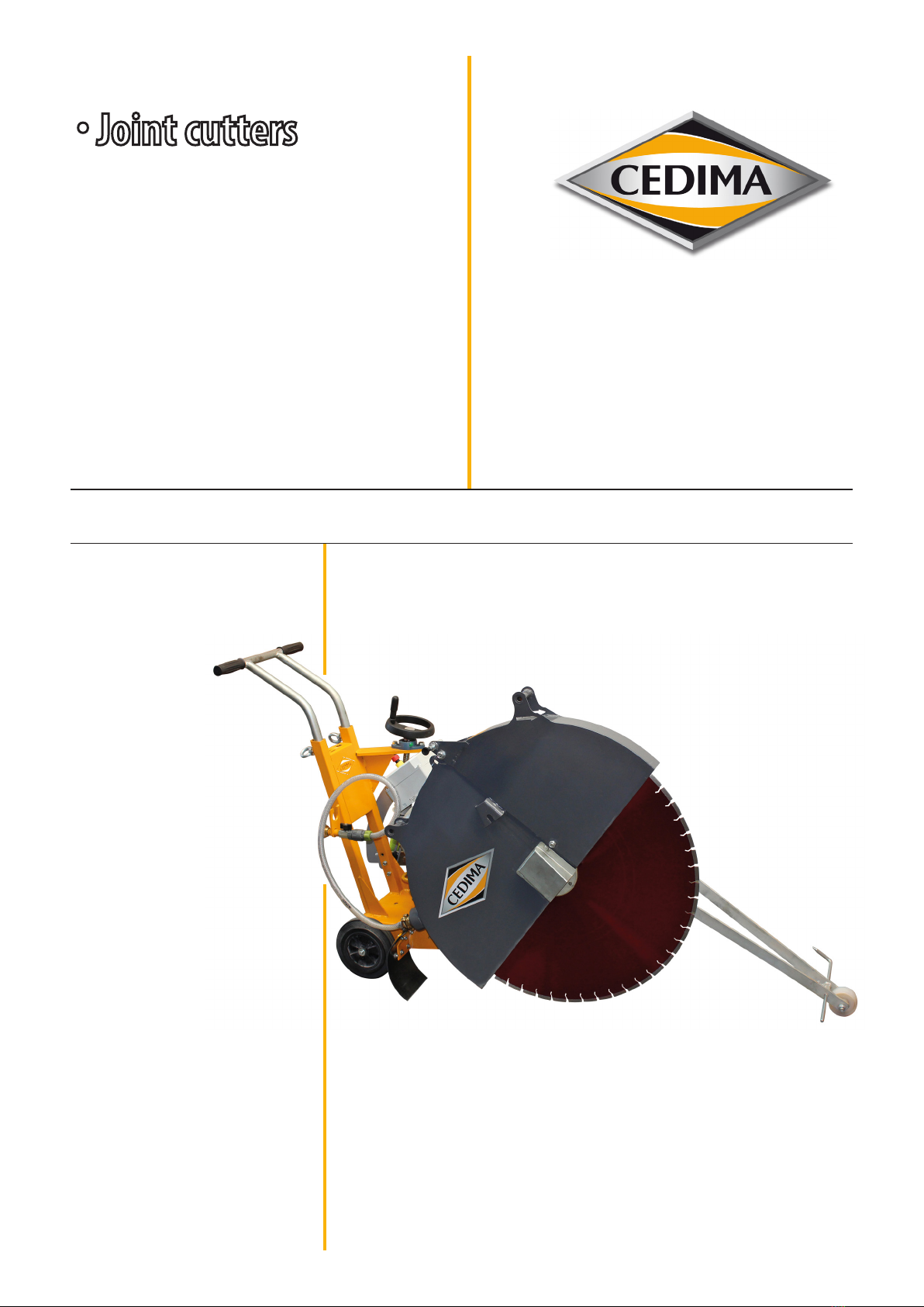
for joint cutters
3.2.1 Designated use, predictable misuse
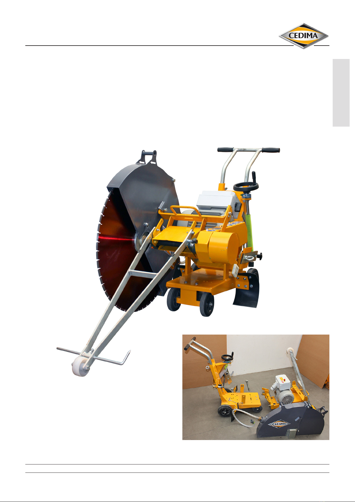
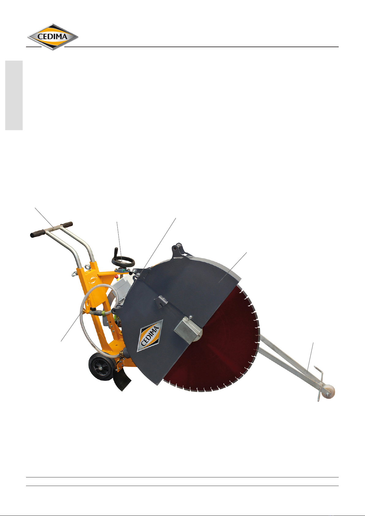
3.2.1.1 The joint cutter CF-22 E.800, in the following
referred to as “the machine”, is exclusively to be used as
a walk-behind hand-guided oor cutting machine for
cutting by means of diamond saw blades in wet cut-
ting operation of rmly installed components made of
asphalt, concrete and abrasive construction material
as used e.g. in roadwork, hall oors and runways! Using
the machine for purposes other than those mentioned
above is considered contrary to its designated use; in
particular the use of the machine with cutting tools
other than those approved by the manufacturer/distrib-
utor is prohibited. The manufacturer/distributor cannot
be held liable for any damage resulting from such use.
The risk of such misuse lies entirely with the user!
3.2.1.2 The machine is not approved for other use than the
one specied herein; this constitutes improper use!
3.2.1.3 Operating the machine within the limits of its
designated use also involves observing the instructions
set out in this operating manual and complying with the
inspection and maintenance directives.
3.2.1.4 The machine has been designed in accordance with
state-of-the-art standards and recognized safety rules.
Nevertheless, its use may constitute a risk to life and limb
of the user or of third parties, or cause damage to the
machine or other material property!
3.2.1.5 The machine must only be used in technically
perfect condition in accordance with its designated
use, the instructions set out in the operating manual
and the relevant national safety regulations, and only
by safety-conscious persons who are fully aware of the
risks involved in operating the machine! Any functional
disorders, especially those aecting the safety of the
machine, must therefore be rectied immediately!
3.2.2 Organizational measures
3.2.2.1 This operating manual must always be at hand at
the place of use of the machine and must be accessible
to the personnel operating the machine.
3.2.2.2 In addition to this operating manual, all other
generally applicable legal and other mandatory
regulations relevant to accident prevention and
environmental protection must be observed. Such
obligations may also comprise the handling of
hazardous materials, provisioning and/or wearing
of personal protective equipment, or road trac
regulations!
3.2.2.3 This operating manual must be supplemented by
instructions covering the duties involved in supervising
and notifying special organizational features, such as job
organization, work ows or the personnel entrusted with
the work.
3.2.2.4 Personnel entrusted with work on the machine
must have read the operating manual, in particular the
chapter "Safety instructions" prior to taking up work!
This applies especially to persons working only
occasionally on the machine, e. g. during set-up or
maintenance activities!
3.2.2.5 Check -at least from time to time- whether the
personnel is carrying out the work in compliance with
the operating manual and paying attention to risks and
safety-relevant factors!
3.2.2.6 For reasons of safety, long hair must be tied back or
otherwise secured, garments must be close-tting and
no jewellery -including rings- may be worn! Severe injury
may result from being caught by moving parts of the
machine!
3.2.2.7 Personal protective equipment must be used
wherever required by the circumstances or by law
(e.g.safety glasses, ear protectors, safety boots, suitable
safety clothing). Depending on the operating conditions
of the machine, other personal safety equipment might
be required! Observe the regulations for the prevention
of accidents!
3.2.2.8 Observe all safety precautions and warnings
attached to the machine and always keep them in good
and perfectly legible condition.
3.2.2.9 In the event of safety-relevant modications or
changes in the behaviour of the machine, stop the
machine immediately and report the malfunction to the
competent authority/person.
3.2.2.10 Do not remove or render inoperative any safety
devices the machine is equipped with!
3.2.2.11 Never make any modications, additions or
conversions which might aect safety without the
manufacturer's/distributor's prior consent. This also
applies to the installation and adjustment of safety
devices as well as to welding work on supporting
structures!
3.2.2.12 Damaged or worn parts of the machine must be
replaced immediately! Only use original spare parts!
3.2.2.13 All spare parts and tools must comply with the
technical requirements specied by the manufacturer/
distributor. With original spare parts, this is always
ensured!
3.2.2.14 Adhere to the legally prescribed preventive
maintenance and inspection intervals or those specied
in this operating manual!
3.2.2.15 Hydraulic hose pipes must be replaced at
prescribed and/or appropriate intervals even if no safety-
relevant defects have been detected!