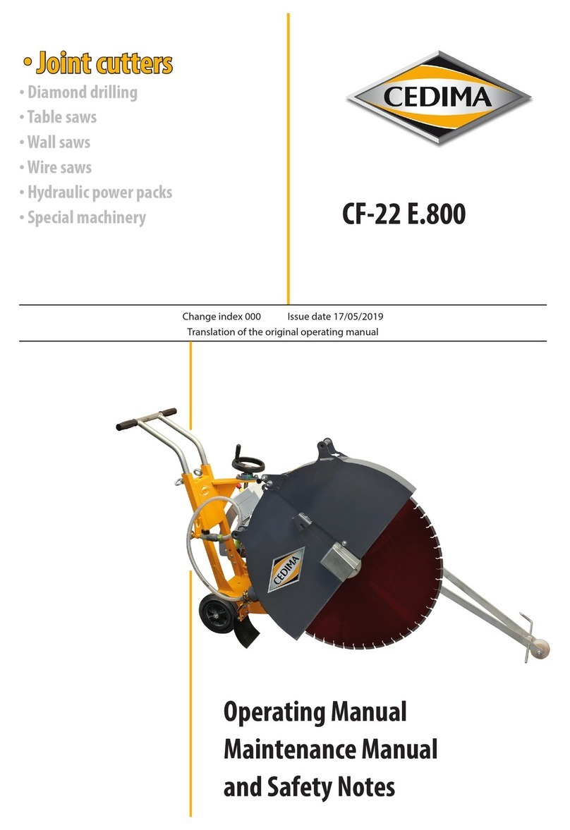
Cedima CF 4030 Operational manual

Translation of the original operating manual
CF•4030
Joint Cutter
Serial number range: 194030001 - xx4030xx
Change index 003 • Issue date: 17.03.2022
English

CEDIMA • Technical Documentation • CF • 4030 Joint Cutter • 194030001 – xx4030xx • Issue Date 17.03.2022
2
Product CF•4030 Joint Cutter
Serial number range 194030001 - xx4030xx
Issued by CEDIMA® Diamantwerkzeug- und Maschinenbaugesellschaft
mbH Lärchenweg 3
29227 Celle
Germany
Phone: +49-(0)5141-8854-100
Fax: +49-(0)5141-8854-111
E-mail: [email protected]om
www: www.cedima.com
This document is protected by copyright. All rights reserved. It is prohibited to copy,
reproduce, translate or convert this document into an electronic medium or into
amachine-readable form, as a complete document or in sections, without the
approval of CEDIMA® Diamantwerkzeug- und Maschinenbaugesellschaft mbH.
Subject to change without prior notice.
Suggestions and
notes ... to this documentation or to the machine should be sent to the address
named above.
Last amended 17/03/2022

CEDIMA • Technical Documentation • CF • 4030 Joint Cutter • 194030001 – xx4030xx • Issue Date 17.03.2022 3
Contents
1. Product information .......................................................................................................................6
1.1 Characteristic data .......................................................................................................................................... 6
1.2 Limits of machine ............................................................................................................................................ 6
1.2.1 Limits of use................................................................................................................................6
1.2.2 Spatial limits..............................................................................................................................10
1.2.3 Temporal limits ........................................................................................................................11
1.3 Manufacturer’s ID label................................................................................................................................11
1.4 Technical specications...............................................................................................................................12
1.5 Scope of delivery ...........................................................................................................................................13
1.5.1 Accessories supplied..............................................................................................................14
1.5.2 Spare parts, optional accessories......................................................................................14
1.5.3 Other relevant documents..................................................................................................14
1.6 Recommended accessories for operating readiness........................................................................14
1.7 EC Declaration of Conformity....................................................................................................................15
2. Information for the reader ...........................................................................................................16
2.1 Validity...............................................................................................................................................................16
2.2 Illustrations ......................................................................................................................................................16
2.3 Abbreviations used.......................................................................................................................................16
2.4 Highlighted passages ..................................................................................................................................17
2.4.1 Pictographs...............................................................................................................................17
2.4.2 Safety instructions..................................................................................................................17
2.4.3 Warnings ....................................................................................................................................18
2.4.4 Handling Instruction..............................................................................................................18
3. Safety .............................................................................................................................................19
3.1 Safety instructions.........................................................................................................................................19
3.1.1 Notes on operating safety ...................................................................................................19
3.1.2 Notes on operation ................................................................................................................20
3.1.3 Notes on commissioning machine...................................................................................21
3.1.4 Notes on shutting down machine....................................................................................21
3.1.5 Notes on maintenance and repairs ..................................................................................21
3.1.6 Notes on transport .................................................................................................................22
3.1.7 Notes on environmental protection ................................................................................22
3.1.8 Impermissible operating conditions................................................................................22
3.2 Local regulations............................................................................................................................................23
3.3 Operator’s obligations .................................................................................................................................23
3.3.1 Planning and checking safety measures........................................................................23
3.3.2 Minimising risk of injury.......................................................................................................24
3.3.3 Operating machine fault-free.............................................................................................24
3.3.4 Precautions in case of re ....................................................................................................25
3.4 Qualications of personnel........................................................................................................................25
3.5 Safety equipment..........................................................................................................................................25
3.5.1 Notes on safety equipment.................................................................................................25
3.5.2 Fixed safety equipment........................................................................................................26
3.5.3 Movable safety equipment .................................................................................................28
3.5.4 Signalling devices...................................................................................................................28
3.5.5 Emergency-Stop devices......................................................................................................28
3.5.6 Triggering Emergency-Stop function..............................................................................29
3.5.7 Resetting Emergency-Stop function ...............................................................................29
3.6 Signs on the Machine...................................................................................................................................30
3.6.1 Warning signs...........................................................................................................................30
3.6.2 Additional adhesive labels...................................................................................................31

CEDIMA • Technical Documentation • CF • 4030 Joint Cutter • 194030001 – xx4030xx • Issue Date 17.03.2022
4
3.7 Residual danger .............................................................................................................................................31
3.8 Instructions for rst aid................................................................................................................................35
3.9 What to do in case of a re.........................................................................................................................36
4. Machine overview .........................................................................................................................37
4.1 Parts of the machine.....................................................................................................................................37
4.1.1 Overview....................................................................................................................................37
4.1.2 Machine components – Right side...................................................................................38
4.1.3 Blade guard...............................................................................................................................39
4.1.4 Cutting shaft with blade guard holder ...........................................................................40
4.1.5 Machine components – Front side...................................................................................41
4.1.6 Machine components – Top of the machine ................................................................43
4.1.7 Machine components – Rear side.....................................................................................44
4.1.8 Machine components – Left side......................................................................................45
4.2 Working and danger areas.........................................................................................................................46
4.3 Operating elements......................................................................................................................................47
4.3.1 Operating console..................................................................................................................47
4.3.2 Safety devices...........................................................................................................................52
4.4 Operating description..................................................................................................................................53
5. Transporting and setting down ...................................................................................................54
5.1 Transporting machine..................................................................................................................................54
5.2 Unpacking machine .....................................................................................................................................54
5.3 Requirements for environment................................................................................................................54
5.4 Lifting and setting down machine..........................................................................................................55
5.5 Driving machine onto a trailer or a truck bed.....................................................................................57
5.6 Fastening points for lashing ......................................................................................................................58
6. Control system...............................................................................................................................59
6.1 Monitor..............................................................................................................................................................59
6.2 Operating screens of control system......................................................................................................60
6.2.1 Start screen ...............................................................................................................................60
6.2.2 DPF...............................................................................................................................................62
6.2.3 Engine fault...............................................................................................................................64
6.2.4 Service.........................................................................................................................................65
7. Retrotting ....................................................................................................................................66
7.1 Removing and tting the blade guard..................................................................................................66
7.1.1 Removing blade guard .........................................................................................................66
7.1.2 Fitting blade guard.................................................................................................................69
7.2 Fitting and removing the cutting shaft protective cover................................................................69
7.2.1 Removing the cutting shaft protective cover...............................................................69
7.2.2 Fitting the cutting shaft protective cover......................................................................70
7.3 Removing and tting the visors...............................................................................................................71
7.3.1 Removing the visors ..............................................................................................................71
7.3.2 Fitting visors..............................................................................................................................72
8. Operation.......................................................................................................................................73
8.1 Operating machine.......................................................................................................................................73
8.2 Commissioning ..............................................................................................................................................73
8.2.1 Check the scope of delivery................................................................................................73
8.2.2 Notes on commissioning machine...................................................................................74
8.2.3 Commissioning machine .....................................................................................................75

CEDIMA • Technical Documentation • CF • 4030 Joint Cutter • 194030001 – xx4030xx • Issue Date 17.03.2022 5
8.3 Daily start-up...................................................................................................................................................77
8.3.1 Prerequisites for daily start-up...........................................................................................77
8.3.2 Switching on machine ..........................................................................................................78
8.3.3 Fitting and removing diamond saw blade ....................................................................80
8.3.4 Moving machine .....................................................................................................................88
8.3.5 Aligning the machine on the cut ......................................................................................90
8.3.6 Connecting the ushing water..........................................................................................93
8.3.7 Setting the depth of the cut ...............................................................................................94
8.3.8 Carrying out cutting process..............................................................................................96
8.4 Troubleshooting ..........................................................................................................................................104
8.4.1 Diesel engine.........................................................................................................................104
8.4.2 Electrical system...................................................................................................................105
8.4.3 Hydraulic system..................................................................................................................106
8.4.4 Cutting process.....................................................................................................................106
8.5 Daily shut-down...........................................................................................................................................108
9. Maintenance, repairs and shut-down........................................................................................110
9.1 Notes on maintenance and repairs.......................................................................................................110
9.2 Performing test work..................................................................................................................................112
9.2.1 Checking ll level of hydraulic oil tank ........................................................................112
9.2.2 Checking ll level of diesel tank .....................................................................................112
9.2.3 Checking ll level of coolant tank..................................................................................113
9.2.4 Checking air lter.................................................................................................................114
9.3 Fitting and removing protective covers..............................................................................................116
9.3.1 Fitting and removing side panels ..................................................................................116
9.4 Relling operating materials...................................................................................................................118
9.4.1 Relling diesel.......................................................................................................................118
9.4.2 Relling hydraulic oil..........................................................................................................120
9.4.3 Checking, lling and changing gear oil in wheel hubs..........................................122
9.4.4 Relling coolant....................................................................................................................124
9.4.5 Relling the engine oil.......................................................................................................124
9.5 Maintenance schedule ..............................................................................................................................125
9.6 Maintenance work.......................................................................................................................................127
9.6.1 Changing hydraulic oil and hydraulic oil lter ..........................................................127
9.6.2 Cleaning dirt trap of water supply lter.......................................................................129
9.6.3 Servicing and replacing battery .....................................................................................130
9.6.4 Cleaning the impeller of the ushing water pump.................................................132
9.7 Operating materials and lubricants......................................................................................................133
9.7.1 Specication of hydraulic oil............................................................................................133
9.7.2 Specication of gear oil.....................................................................................................133
9.7.3 Specication of engine oil................................................................................................134
9.7.4 Specication of diesel fuel................................................................................................134
9.7.5 Specication of engine coolant......................................................................................134
9.7.6 Specication of grease for general lubrication points ...........................................134
9.7.7 Filling quantities and change intervals........................................................................135
9.8 Lubricating points.......................................................................................................................................135
9.9 Cleaning..........................................................................................................................................................135
9.9.1 Notes about cleaning.........................................................................................................135
9.9.2 Dry cleaning...........................................................................................................................136
9.9.3 Wet cleaning..........................................................................................................................136
9.10 Safety data sheets .......................................................................................................................................137
9.11 Long-term shut-down ...............................................................................................................................137
9.12 Shut-down .....................................................................................................................................................137
9.12.1 Storage when not in use ...................................................................................................137
9.12.2 Disposal...................................................................................................................................138

CEDIMA • Technical Documentation • CF • 4030 Joint Cutter • 194030001 – xx4030xx • Issue Date 17.03.2022
6
1 Product information
This chapter contains information on the machine:
• Characteristic data (Page 6)
• Limits of machine (Page 6)
• Manufacturer‘s ID label (Page 11)
• Technical specications (Page 12)
• cope of delivery (Page 13)
• Recommended accessories for operating readiness (Page 14)
• EC Declaration of Conformity (Page 15)
1.1 Characteristic data
Characteristic data of machine
Machine model CF•4030 Joint Cutter
Serial number
range
194030001 - xx4030xx
Year of manufacture 2019 - 20xx
1.2 Limits of machine
The machine may only be operated within the limits specied by the manufacturer. If these
limits are not complied with, this is considered to be improper use. The following limits are
dened for the machine:
• Limits of use (Page 6)
• Spatial limits (Page 10)
• Temporal limits (Page 11)
1.2.1 Limits of use
1.2.1.1 Proper use
The freely moveable, walk-behind hand-guided machine is only approved for wet cutting of
rmly installed components using manufacturer-approved diamond saw blades.
The components can consist of:
• Cured concrete with or without reinforcement
• Green concrete with or without reinforcement
• Asphalt
Any other or additional use is considered improper.

Limits of machine
Product information
CEDIMA • Technical Documentation • CF • 4030 Joint Cutter • 194030001 – xx4030xx • Issue Date 17.03.2022 7
The intended use also includes compliance with all information of these original operating
instructions, as well as compliance with safety-relevant parameters and not exceeding the
limits of the machine.
The manufacturer shall not be liable for damage caused by the improper use of the machine.
The user or operator bears the sole risk for this. The warranty shall become void if the
product is used contrary to its intended purpose.
1.2.1.2 Design limits
In addition to the parameters mentioned in the following table, the specications in the
technical data of this machine belong to the design limits. Additional information about the
technical specications can be found in the chapter“Technical Specications”(Page 12).
Design limits
Type of design limit Value
Cutting tool Diamond saw blades approved by the manufacturer
Cutting material Cured concrete with or without reinforcement,
green concrete with or without reinforcement
Asphalt
1.2.1.3 Reasonably foreseeable misuse
The following actions are among the reasonably foreseeable misuses recognised by the
manufacturer:
• Dismantling or bypassing safety equipment.
• Failure to use the prescribed personal protective equipment.
• Operation outside the design limits.
Not all possible misuses can be considered. Based on experience with the machine and
humanbehaviour, the reasonably foreseeable misuse is stated to the best of our knowledge
and belief.
1.2.1.4 Operating modes
The machine is designed for the following types of operation:
• Hand-guided automatic operation
1.2.1.5 Human-machine interfaces
The machine ready for operation is operated at the following human-machine interface:
• Operating console
There are various human-machine interfaces for setting up, maintaining, servicing and clean-
ing the machine (see Original operating manual > Chapter„Overview of the machine“)
• Machine components – Left side
• Machine components – Rear side
• Machine components – Top of machine
• Machine components – Front side
• Front visor
• Machine components – Right side
• Blade guard

Limits of machine
Product information
CEDIMA • Technical Documentation • CF • 4030 Joint Cutter • 194030001 – xx4030xx • Issue Date 17.03.2022
8
1.2.1.6 User groups
Without exception, the regulations and measures to be observed for safety and health
protection in the performance of tasks must be formulated and interpreted in such a way that
the employees are able to comply with them.
All work on the machine requires the personnel to possess special knowledge and skills.
Anyone who works on the machine must meet the following conditions, i.e. they must:
• Be personally suited for the respective activity.
• Be suciently qualied for the respective activity.
• Be instructed in handling the control elements of the machine.
• Be familiar with the safety equipment and its operation.
• Be familiar with this operating manual, and in particular with the safety instructions and
with the sections relevant for the activity.
• Be familiar with basic regulations on occupational safety and accident prevention.
All persons must always provide proof of one of the following minimum qualications:
• Have been trained as a specialist to work independently on the machine.
• Have received sucient instruction to work on the machine under the supervision of
atrained specialist.
A distinction is made between the following user groups:
User groups
Personnel Qualications
Operating personnel Appropriate instruction in the areas:
• Functional sequences of the machine
• Operating sequences
• Quality evaluation
Knowledge in the areas:
• Expertise and responsibilities for the activity
• Behaviour in case of malfunctions
Maintenance personnel In-depth knowledge in the areas:
• Mechanical engineering
• Electrical engineering
• Hydraulics
Authorisation for the activities (according to the standards of
safety engineering):
• Commissioning of devices
• Earthing of devices
• Marking of devices
Authorisation for the activities:
• Undertake the necessary settings in the controls
• Perform manual traverse movements with
the machine
In-depth knowledge of the design and function of the
machine.
Secure control and implementation of the Lockout/Tagout
procedure.

Limits of machine
Product information
CEDIMA • Technical Documentation • CF • 4030 Joint Cutter • 194030001 – xx4030xx • Issue Date 17.03.2022 9
The following activities may only be carried out by personnel with specialised knowledge:
User groups
Activity Qualications
Working on electrical
equipment
Electrician or a qualication going beyond that.
The qualied electrician must be professionally qualied
in the eld of electrical engineering and, on the basis of
trainingand experience, must be able to recognise risks and
avoid possible dangers from electricity (ve safety rules).
Training elements:
• Assembly and disassembly of components and assemblies
• Measurement, evaluation and calculation of electrical
variables
• Testing and evaluation of protective measures
• Installation, wiring and labelling of switchgear
• Integrating IT systems in networks
• Hazards associated with the operation of electrical
equipment and machinery, assessment of these hazards
and protective measures for safe use
• Ensuring electrical supply and safety of equipment
• Assessment of existing machines of the operating
technology
• Testing and evaluation of control and regulating systems
• Testing of Emergency-Stop and signalling systems of
mechanical safety devices
• Maintaining machines and systems according to
maintenance and repair schedules and replacing wearing
parts as part of preventive maintenance
• Application of occupational safety and accident
prevention regulations and environmental protection
measures
The qualied electrician must have sound knowledge of the
structure and function of the machine and must have read
and understood the operating instructions.
The electrician must be trained on the machine by
the manufacturer or by a specialist authorised by the
manufacturer.

Limits of machine
Product information
CEDIMA • Technical Documentation • CF • 4030 Joint Cutter • 194030001 – xx4030xx • Issue Date 17.03.2022
10
User groups (Continued)
Activity Qualications
Work on mechanical and
hydraulic equipment
Industrial mechanic or at least equivalent training.
Training elements:
• Reading and applying foundation, site and installation
plans
• Basics in the assembly and repair of industrial machines
• Basics of pneumatic machines and parts
• Inspection, care, repair, improvement and maintenance of
equipment and documentation of these activities
• Limitation and detection of faults in machines and
systems by controlling, regulating and monitoring work
movements and their auxiliary functions
• Set-down, storage and securing of transported goods
• Application of occupational safety and accident
prevention regulations and environmental protection
measures
• Special knowledge of and experience in working with
hydraulics.
The mechanic must have sound knowledge of the structure
and function of the machine and must have read and
understood the operating instructions.
The mechanic must be trained on the machine by
the manufacturer or by a specialist authorised by the
manufacturer.
1.2.2 Spatial limits
The machine may only be used in the designated and appropriately protected environment.
In particular, the following conditions must be met:
• Access to the machine is monitored wherever possible. The keys for starting the machine
must only be in the possession of persons authorised by the operator.
• Suitable organisational measures ensure proper supply and disposal of the machine.
Special protection alongside company employees applies to the following groups:
• Trainees:
• Employees from external companies (cleaning, maintenance, training, etc.)
• Temporary workers
• Visitors
• Emergency rescue services

Manufacturer’s ID label
Product information
CEDIMA • Technical Documentation • CF • 4030 Joint Cutter • 194030001 – xx4030xx • Issue Date 17.03.2022 11
1.2.3 Temporal limits
If all maintenance intervals / maintenance work and the conditions and prerequisites
mentioned in this original operating manual are observed, a service life of at least ten years
can be expected of the machine.
Safe usage of the machine over this service life presupposes operation of the machine within
the limits of its performance. Additional prerequisites include observance of the prescribed
maintenance intervals and maintenance work.
For more information about maintenance intervals and maintenance work, please refer to the
operating manual.
1.3 Manufacturer’s ID label
The manufacturer’s ID label can be found at the following location on the machine:
Location of the manufacturer’s ID label
CF•4030
2019 - 20xx
194030001 - xx4030xx
935
41
Illustration of machine ID label

Technical specications
Product information
CEDIMA • Technical Documentation • CF • 4030 Joint Cutter • 194030001 – xx4030xx • Issue Date 17.03.2022
12
1.4 Technical specications
Machine dimensions
Machine length 1,893 mm (with blade guard)
Machine width 1,278 mm
Machine height 1,408 mm
Total machine weight 1,029 kg
Working area
Maximum cutting depth (Version A)
200 mm
Maximum cutting depth (Version B)
300 mm
Maximum cutting depth (Version C)
400 mm
Blade diameter (Version A) 600 mm dia.
Blade diameter (Version B) 800 mm dia.
Blade diameter (Version C) 1,000 mm dia.
Diamond saw blade holder right and left
Cutting-shaft speed 560 rpm (with a roughing speed of 1000 rpm)
1,650 rpm (at full load 2,300 rpm)
Saw blade ange diameter 150 mm dia.
Maximum width of diamond saw
blade tensioning range
20 mm
6 hole reference diameter 120 mm dia. (with 14 mm dia. holes)
Diameter of diamond saw-blade
receptacle pin
35 mm dia. (with 10 mm dia. driving bore)
TK: 58 mm)
Fuel tank 28.5 l
Hydraulic tank 20 l
Environment
Sound pressure level at the
workplace (LpA)
86 dB [A]
Measured sound pressure level
(LWA)
102 dB [A]
Equivalent vibration total value
(a) | (hand-arm vibrations)
6.6 m/s²
Equivalent vibration total value
(a) | (whole body vibration)
in x-direction 3.6 m/s²
in y-direction 2.6 m/s²
in z-direction 0.6 m/s²

Scope of delivery
Product information
CEDIMA • Technical Documentation • CF • 4030 Joint Cutter • 194030001 – xx4030xx • Issue Date 17.03.2022 13
Drives
Drive motor Make: DOOSAN
Model: D18
Type: Diesel
Engine starting Electric starter
Displacement 1,794 cm³
Battery 12 V | 100 Ah
Output 41 kW
Diamond saw-blade drive Diesel engine via hydraulically engaged belt drive
Cutting depth infeed hydraulic
Feed hydraulic
Travel speed 0 m/min - 42 m/min
Fuel consumption at full load 9 l - 10 l/h
Water supply GEKA coupling, via ON / OFF switchable electric
impeller pump
Water consumption 500 l/h - 800 l/h
Emission standard Level IV (EU) and EPA TIER 4 nal (USA)
Operating materials
Gearbox | Brakes Gearbox oil ISO VG 150
Filling quantity: 0.7 l
Engine | Oil ACEA E6 or E9, ACEA C3 / C4, API CJ-4
Bio-Hydraulic oil Bio hydraulic oil HYHE46 DIN ISO 15380
lling quantity: total approx. 65 l, tank capacity:
Antifreeze BASF Glysantin® G30®, Glysantin® G40®,
ARAL Aral Antifreeze Silicate-Free
1.5 Scope of delivery
The machine is delivered ready to operate. When receiving goods, the completeness of the
scope of delivery must be checked. Any missing or damaged parts must be reported to
CEDIMA® Diamantwerkzeug- und Maschinenbaugesellschaft mbH immediately in writing.
The machine is:
• Completely lled with engine oil,
• Completely lled with hydraulic oil,
• Completely lled with gear oil
• Completely lled with coolant
• Slightly lled with fuel (diesel-oil)

Recommended accessories for operating readiness
Product information
CEDIMA • Technical Documentation • CF • 4030 Joint Cutter • 194030001 – xx4030xx • Issue Date 17.03.2022
14
1.5.1 Accessories supplied
The machine is delivered with the following accessories:
• Two tank keys
• Two ignition keys
• Two open-ended spanners (WAF 17)
• One square wrench (cladding spanner)
1.5.2 Spare parts, optional accessories
No spare parts are delivered with the machine. Spare parts are available on request.
The spare parts list is contained in the supplier documentation for this machine.
Ask for optional accessory parts directly from CEDIMA® Diamantwerkzeug- und
MaschinenbaugesellschaftmbH.
1.5.3 Other relevant documents
All documents supplied are also valid documents. Keep the complete supplier
documentation supplied by the manufacturer. The following documents are part of the scope
of delivery of this machine:
• Operating manual of diesel engine (DOOSAN).
• Operating instructions of any attachment kits.
1.6 Recommended accessories for operating readiness
Recommended accessories for operating readiness
Description
Driver‘s step with adjustable seat
Suction unit for CF-4030 joint cutter
ABS 4.2 with holder and suction blade guard
For damage resulting from using accessories that are not in accordance with CEDIMA®,
wewill refuse any liability.
For special applications, please ask CEDIMA® directly.
For further accessories refer to the current CEDIMA® price list.

EC Declaration of Conformity
Product information
CEDIMA • Technical Documentation • CF • 4030 Joint Cutter • 194030001 – xx4030xx • Issue Date 17.03.2022 15
1.7 EC Declaration of Conformity
EC Declaration of Conformity
according to Machinery Directive 2006/42/EC Appendix II A and
Outdoor Directive 2000/14/EC Appendix II
Manufacturer CEDIMA® Diamantwerkzeug- und Maschinenbaugesellschaft mbH
Lärchenweg 3, D-29227 Celle, Germany
Product Joint Cutter
Product variant CF•4030 Joint Cutter
Serial number 194030001 - xx4030xx
Year of manufacture 2019 - 20xx
Measured sound
pressure level (LWA)
111 dB [A]
Measured sound pressure
level at the workplace (LpA)
103 dB [A]
Operating description The freely movable hand-guided machine is used for wet cutting in
asphalt, cured concrete or green concrete using diamond saw blades
approved by the manufacturer.
We hereby declare that the design and construction of this machine in the version we have
placed on the market comply with the essential health and safety requirements of the
ECdirectives listed in the following:
2006/42/EC Machinery Directive
2000/14/EC Directive on Noise Emission by Outdoor Machinery
This machine complies with the standards listed in the following:
DIN EN ISO 12100-1 Safety of machinery - Basic terms, general principles for design -
Part 1: Basic terminology, methodology
DIN EN ISO 12100-2 Safety of machinery - Basic terms, general principles for design -
Part 2: Technical principles
DIN EN ISO 60204-1 Safety of machinery - Electrical equipment of machinery -
Part 1: General requirements
Documentation Manager of the
CEDIMA® Diamantwerkzeug- und Maschinenbaugesellschaft mbH,
Lärchenweg 3, D-29227 Celle
This declaration of conformity immediately becomes invalid if changes are incorporated
to the machine which have not been approved by CEDIMA® Diamantwerkzeug- und
Maschinenbaugesellschaft mbH!
Celle, Germany, 28/10/2020
Place, date Bob Siemsen, Managing Director
EC Declaration of Conformity
This declaration becomes void as soon as major modications are made to the machine.
Anew conformity procedure in accordance with the EU machinery directive is then required.

CEDIMA • Technical Documentation • CF • 4030 Joint Cutter • 194030001 – xx4030xx • Issue Date 17.03.2022
16
Abbreviations used
Information for the reader
2 Information for the reader
This chapter contains information on using the operating manual:
• Validity (Page 16)
• Illustrations (Page 16)
• Abbreviations used (Page 16)
• Highlighted passages (Page 17)
2.1 Validity
This original operating manual contains information and rules for conduct for safe operation
of the machine. Read the original operating manual carefully before commissioning. Keep the
original operating manual at hand for everyone.
To operate the machine eectively, the original operating manual provides information
among other things on the following topics:
• Transporting, installing and putting the machine into operation
• Working with the machine
• Performing care and maintenance on machine
• Detecting and eliminating malfunctions
This operating manual applies to:
• the operator
• all persons who work on or with the machine
2.2 Illustrations
The illustrations in this original operating manual show the machine in a simplied form in
some cases.
2.3 Abbreviations used
The following abbreviations are used in the operating manual:
Abbreviations
CF Cedima Joint Cutter

Highlighted passages
Information for the reader
CEDIMA • Technical Documentation • CF • 4030 Joint Cutter • 194030001 – xx4030xx • Issue Date 17.03.2022 17
2.4 Highlighted passages
In this operating manual, important information is emphasised with symbols or special styles
of writing. The following examples show the most important forms of highlighting:
• Pictographs (Page 17)
• Safety instructions (Page 17)
• Warnings (Page 18)
• Handling instructions (Page 18)
2.4.1 Pictographs
Pictographs used
Pictograph Meaning
Additional, useful information.
Conditions that must be fullled in order to perform an action.
Tools or materials required to perform an action.
2.4.2 Safety instructions
Safety instructions: Special instructions for an informative section.
Explanation of the instructions.
• The point indicates measures for taking the instructions into account.

Highlighted passages
Information for the reader
CEDIMA • Technical Documentation • CF • 4030 Joint Cutter • 194030001 – xx4030xx • Issue Date 17.03.2022
18
2.4.3 Warnings
DANGER
Warning on fatal injuries.
Failure to observe the warning can result in serious damage to health or even death.
The arrow indicates a precautionary measure which must be taken to avert the hazard.
WARNING
Warning of serious injuries.
Failure to observe the warning can result in serious damage to health or even death.
The arrow indicates a precautionary measure which must be taken to avert the hazard.
CAUTION
Warning of injuries.
Failure to observe the warning can result in damage to health.
The arrow indicates a precautionary measure which must be taken to avert the hazard.
ATTENTION
Warning of damage.
Failure to observe the warning can result in considerable damage to the machine or the sur-
rounding area.
The arrow indicates a precautionary measure which must be taken to avert the hazard.
2.4.4 Handling Instruction
Carry out the following steps: = Start of handling instruction.
1. First step in a sequence of steps.
Required settings . . . Adjustment values
2. Second step in a sequence of steps.
Result of this step.
The step is completed and the objective has been achieved.

Safety instructions
Safety
CEDIMA • Technical Documentation • CF • 4030 Joint Cutter • 194030001 – xx4030xx • Issue Date 17.03.2022 19
3 Safety
This chapter contains information on the safe operation of the machine:
• Safety instructions (Page 19)
• Local regulations (Page 23)
• Operator’s obligations (Page 23)
• Qualications of personnel (Page 25)
• Safety equipment (Page 25)
• Signs on machine (Page 30)
• Residual danger (Page 31)
• Instructions for rst aid (Page 35)
• What to do in case of a re (Page 36)
3.1 Safety instructions
These safety instructions are intended for the operator and the user of the machine:
• Notes on operating safety (Page 19)
• Notes on operation (Page 20)
• Notes on commissioning the machine (Page 21)
• Notes on shutting the machine down (Page 21)
• Notes on maintenance and repairs (Page 21)
• Notes on transport (Page 22)
• Notes on environmental protection (Page 22)
• Impermissible operating conditions (Page 22)
3.1.1 Notes on operating safety
The machine is safe to operate. It has been built in accordance with state-of-the-art science
and technology.
Nevertheless, the machine may present hazards:
• If the machine is not used for the intended purpose.
• If the machine is used improperly.
• If the machine is operated under impermissible conditions.
The following instructions apply to anyone who works on or with the machine:
• Please note that the diesel engine heats up during operation.
• Please ensure that no one can be injured by moving parts and hot parts of the machine
during cleaning and converting work.
• Make sure that all safety devices have been installed.
• Report any changes in the sequence of movements or faults immediately.
• Never wear clothing or objects, such as necklaces or bracelets that can get caught in
moving assemblies.

Safety instructions
Safety
CEDIMA • Technical Documentation • CF • 4030 Joint Cutter • 194030001 – xx4030xx • Issue Date 17.03.2022
20
3.1.2 Notes on operation
Safety-conscious, foresighted behaviour of the personnel prevents dangerous situations
during operation.
Observe the following points when working with the machine:
• Before starting work, familiarise yourself with the surroundings and circumstances of the
site. This includes obstacles which might impede work, the soil bearing capacity and the
required safety measures, e.g. barriers separating the work site from public trac and the
possibility to render rst aid in case of accidents.
• Clear the operating site of anything that could impede work.
• Only commission the machine with qualied personnel.
• Only operate the machine with qualied personnel.
• Ensure that persons to be trained or persons taking part in a general training course work
on the machine only under the supervision of a trained and experienced person.
• Before operation, make sure that the diamond saw blade is rmly mounted.
• Before operation, make sure that the diamond saw blade is in proper condition.
• Carry out the cutting process only with a constant water supply.
• Always wear the prescribed protective equipment during operation.
• Defects or damaged components of the machine must be replaced immediately.
Useonly original spare parts!
• All spare parts and tools must comply with the technical requirements specied by the
manufacturer. With original spare parts, this is always ensured.
• Adhere to the legally prescribed intervals for testing and inspection of the machine and
those specied in this operating manual!
• Only eliminate faults when the machine is switched o in the“safe O” state. To do this,
actuate the Emergency-Stop switch.
• Never change, dismantle or bypass safety equipment.
• Never remove safety equipment from operation.
• Never make structural changes to the machine. This also applies to the installation and
conguration of safety devices as well as to welding and drilling work on supporting
structures.
• Never change the work areas.
• Report any change to the machine immediately to the responsible person.
• Always keep the danger areas clear. Only enter the danger areas with the machine de-
energised. Never place objects in the danger zones.
• Observe the re and explosion danger when refuelling the machine! Never pour fuel
onto hot machine parts!
• Never operate the machine in closed rooms. Make sure that the machine is only operated
in adequately ventilated rooms.
• Continuously monitor the machine during operation. Switch o the machine
immediately if a malfunction occurs.
• Never travel across slopes exceeding 5%!
• Always use safety ropes when operating the machine on sloping terrain exceeding 10%!
Table of contents
Other Cedima Cutter manuals
Popular Cutter manuals by other brands

EINHELL
EINHELL BT-KF 150 Original operating instructions

Connex
Connex COX790110 operating manual

AMTI Products
AMTI Products Slice 141 operating instructions

Cembre
Cembre B-TC065-SC Operation and maintenance manual

Gerber
Gerber Tempo 600 Setup manual and quick start guide

METAWOOD
METAWOOD MTSO1400-210 Original instructions