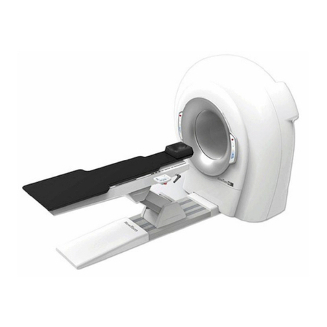
CEFLA NewTom GiANO HR User manual

GiANO HR
Sede legale ed amministrativa / Head Quarter
CEFLA s.c. Via Selice Prov.le 23/a - 40026 Imola (BO) - Italy
tel.+39 0542 653111 / fax +39 0542 653344
After Sales Service
Plant Via Bicocca 14/C 40026 Imola (BO) - Italy
tel.+39 0542 653742 / service.radiology@cefla.it
Technical manual
cod. 97071236 - rev. 02 / 10.06.19


97071236
rev.02
10.06.2019
EN


1
NewTom GiANO HR - TECHNICAL MANUAL
EN CONTENTS
Contents
1. GENERAL WARNINGS...............................................................................................................................................................3
1.1 Foreword ..............................................................................................................................................................................3
1.2 Safety instructions................................................................................................................................................................3
2. PACKAGING AND HANDLING...................................................................................................................................................7
2.1 Handling and storage ...........................................................................................................................................................7
2.2 Damage during shipment .....................................................................................................................................................7
3. PREINSTALLATION....................................................................................................................................................................9
4. DEVICE INSTALLATION AND CALIBRATION ........................................................................................................................ 11
4.1 Assembly instructions......................................................................................................................................................... 11
4.1.1 Removal of packaging............................................................................................................................................ 11
4.1.2 Transport with cart ..................................................................................................................................................12
4.1.3 Wall mounting.........................................................................................................................................................12
4.1.4 Support base oor mounting instructions ...............................................................................................................13
4.1.5 Transport with handles ...........................................................................................................................................13
4.1.6 Safety screws removal ...........................................................................................................................................13
4.1.7 Patient arm installation ...........................................................................................................................................14
4.1.8 Electrical connecions on Mainboard.......................................................................................................................17
4.1.9 Electrical connections on the PFC board ...............................................................................................................18
4.1.10 Ethernet connections and X-Ray emission key....................................................................................................19
4.1.11 CEPH arm installation...........................................................................................................................................20
4.1.12 Electrical connecions on Mainboard.....................................................................................................................25
4.1.13 Patient arm’s handles assembly...........................................................................................................................26
4.1.14 Check during the assembling ...............................................................................................................................27
4.1.15 Checking after mechanical installation .................................................................................................................27
4.2 Cover installation................................................................................................................................................................29
4.3 PC conguration ................................................................................................................................................................41
4.3.1 System requirements..............................................................................................................................................41
4.3.2 Preliminary operations............................................................................................................................................41
4.3.3 Operating system settings......................................................................................................................................41
4.3.3.1 Power management settings...................................................................................................................43
4.3.3.2 Operating system optimization settings...................................................................................................45
4.3.3.3 Disabling “Windows Auto-Update Service”..............................................................................................48
4.3.3.4 Disabling Windows update sharing over the network (low data trac) ...................................................50
4.3.3.5 Firewall Settings ......................................................................................................................................51
4.3.3.6 “Windows Defender” settings ..................................................................................................................51
4.3.3.7 Device installation settings ......................................................................................................................54
4.3.4 PC-Device connection ...........................................................................................................................................58
4.3.4.1 Case 1 - Device-PC direct connection (Setting a static IP address on the network card).......................58
4.3.4.2 Case 2 - Device-PC connection over the network (Setting a dynamic IP address on the network card) 60
4.3.5 “Intel Gigabit” network card conguration...............................................................................................................62
4.3.6 “Acquisition Server Plus” software installation........................................................................................................67
4.3.7 “Acquisition Server Plus” conguration...................................................................................................................69
4.3.7.1 Device search and connection ................................................................................................................71
4.3.7.2 Sensor search and connection................................................................................................................74
4.3.8 CBCT panel installation (Only for 3D) ....................................................................................................................78
4.3.9 Pleora driver installation (Only for 3D)....................................................................................................................78
4.3.10 Driver installation checks......................................................................................................................................83
4.3.11 NNT software installation and conguration .........................................................................................................85
4.3.12 Onboard console connection................................................................................................................................95
4.4 2D Calibration ....................................................................................................................................................................99
4.4.1 Tube head warm-up................................................................................................................................................99
4.4.2 Preliminary actions ...............................................................................................................................................102
4.4.3 Machine conguration ..........................................................................................................................................104
4.4.4 Column calibration................................................................................................................................................106
4.4.5 PAN verify XRay alignement ................................................................................................................................ 110
4.4.5.1 Collimator manual rotation .................................................................................................................... 118
4.4.5.2 Horizontal adjustment............................................................................................................................121
4.4.6 PAN Verify Sensor Compliance ............................................................................................................................123
4.4.7 PAN Verify Sensor Calibration..............................................................................................................................125
4.4.8 PAN Verify Mechanical Centering.........................................................................................................................128
4.4.9 Laser Calibration ..................................................................................................................................................132
4.4.10 CEPH Verify X-ray Alignment .............................................................................................................................136
4.4.10.1 Manual rotation....................................................................................................................................144
4.4.10.2 Manual adjustment of vertical position ................................................................................................147
4.4.11 CEPH Verify Sensor Compliance ......................................................................................................................149
4.4.12 CEPH Verify Sensor Calibration ........................................................................................................................152
2
NewTom GiANO HR - TECHNICAL MANUAL
EN
CONTENTS
4.4.13 CEPH Verify Mechanical Centering....................................................................................................................155
4.4.14 Headrest Calibration ..........................................................................................................................................160
4.4.15 Nasion calibration...............................................................................................................................................163
4.4.16 Backup Calibration Data to File..........................................................................................................................165
4.4.17 Aligning the ear guide rings ................................................................................................................................167
4.5 3D Calibration ..................................................................................................................................................................171
4.5.1 Beam Limiter Test.................................................................................................................................................171
4.5.2 Blank Acquisition and Daily Check .......................................................................................................................178
4.5.3 Cylindrical test phantom acquisition (“Mattarellum”).............................................................................................182
4.5.4 3D calibration backup...........................................................................................................................................189
4.5.5 QA Phantom Scan (optional) ................................................................................................................................192
5. CONTROL PANELS AND DISPLAY SYMBOLS ....................................................................................................................205
5.1 Console onboard the machine .........................................................................................................................................205
5.2 Pushbutton panel on CEPH arm ......................................................................................................................................206
6. SERVICE MENU......................................................................................................................................................................207
7. CIRCUIT BOARDS..................................................................................................................................................................209
7.1 Unit block diagram ...........................................................................................................................................................209
7.2 Mainboard (97661808).....................................................................................................................................................210
7.2.1 Connector list........................................................................................................................................................212
7.2.2 Diagnostic leds .....................................................................................................................................................212
7.3 PFC (97661806)...............................................................................................................................................................214
7.3.1 Connector list........................................................................................................................................................216
7.3.2 Diagnostic leds .....................................................................................................................................................216
7.3.3 Fuses....................................................................................................................................................................216
7.4 Inverter (97661954)..........................................................................................................................................................217
7.4.1 Connector list........................................................................................................................................................219
7.4.2 Diagnostic leds .....................................................................................................................................................219
7.5 Converter (97661807) ......................................................................................................................................................220
7.5.1 Connector list........................................................................................................................................................222
7.5.2 Diagnostic leds .....................................................................................................................................................222
7.6 Console power supply (97662070) ..................................................................................................................................223
7.6.1 Connector list........................................................................................................................................................225
7.6.2 Diagnostic leds .....................................................................................................................................................225
7.7 CEPH Terminal Block (97661913)....................................................................................................................................225
7.7.1 Connector list........................................................................................................................................................226
7.8 Console (97662111) .........................................................................................................................................................227
7.8.1 Connector list........................................................................................................................................................228
7.9 Sensor Interface (97661579) ...........................................................................................................................................229
7.9.1 Connector list........................................................................................................................................................230
7.9.2 Diagnostic leds .....................................................................................................................................................230
7.10 5-Port Switch..................................................................................................................................................................231
8. CONNECTIVITY ......................................................................................................................................................................233
8.1 Console IP address amendment......................................................................................................................................233
8.2 2D sensors / 3D panel IP address amendment................................................................................................................234
8.3 Firmware upgrade ............................................................................................................................................................234
8.4 Remote support................................................................................................................................................................236
Appendix - Maintenance procedures for the device equipment..............................................................................................237

3
NewTom GiANO HR - TECHNICAL MANUAL
EN GENERAL WARNINGS
1. GENERAL WARNINGS
1.1 FOREWORD
The device described in this manual is manufactured by CEFLA s.c. - via Selice Provinciale 23/A - 40026 Imola (BO)
Italia, which is the manufacturer, in compliance with the applicable European Directives detailed in the declaration of
conformity.
These technical instructions are addressed to the personnel in charge of repair and/or maintenance operations of
CEFLA s.c. equipment and contain all the necessary information.
CEFLA s.c. shall be responsible for the safety, reliability and eciency of the equipment provided that:
• installation, any modications, settings or repairs are made by authorised technical personnel using CEFLA s.c.
original spare parts
• In case of installation in medical locations: the electrical installation of the relevant location complies with IEC 60364-
7-710:2002 Standards (Standards on electrical installations of medical locations) or with the equivalent Standards in
force in the country of installation
• the equipment is used as outlined in User Manual
• in case of installation of an X-ray unit: The room where the X-ray unit is installed complies with the ocial Directives
on protection from radiation in the country of use
1.2 SAFETY INSTRUCTIONS
All the safety instructions that help prevent any hazardous situations and operate the equipment in a trouble-free
manner are given in the user’s manual as explained below:
SYMBOL DESCRIPTION
ATTENTION: General mandatory action sign
ATTENTION: Wear protective gloves
ATTENTION: Wear foot protection
ATTENTION: Use protective eyewear
ATTENTION: Use protective clothings
ATTENTION: Connect an earth terminal to the ground

4
NewTom GiANO HR - TECHNICAL MANUAL
EN
GENERAL WARNINGS
SYMBOL DESCRIPTION
ATTENTION: Refer to instruction manual-booklet
ATTENTION: Disconnect mains plug from electrical outlet
WARNING: See the technical manual
WARNING: Failure to observe instructions may result in equipment damage or injury to the user
WARNING: High voltage
WARNING: Crushing of hands
WARNING: Radioactive material or ionizing radiation
WARNING: Keep clear of moving parts
WARNING: Laser beam
WARNING: Hot surface
WARNING: Biological hazard
WARNING: Sharp objects
WARNING: Corrosive substances

5
NewTom GiANO HR - TECHNICAL MANUAL
EN GENERAL WARNINGS
SYMBOL DESCRIPTION
WARNING: Combustible and ammable materials
DANGER: Tipping over
DANGER: Heavy object. Two persons are required
WARNING!
ALWAYS DISCONNECT power supply before performing any maintenance or cleaning operation.
The packed device must be handled using, where possible, suitable mechanical means (forklift, pallet
truck, etc.) and following the indications on the package.
In case of manual handling, the device must be lifted by several persons using the suitable available
means and, if possible, it must be moved with a truck or similar means.
Wear the proper protections

6
NewTom GiANO HR - TECHNICAL MANUAL
EN
GENERAL WARNINGS

7
1
2
3
4
5
NewTom GiANO HR - TECHNICAL MANUAL
EN PACKAGING AND HANDLING
2. PACKAGING AND HANDLING
2.1 HANDLING AND STORAGE
Indications regarding storage, handling and unpacking are given on the outside of the cardboard packaging.
These indications must be strictly observed.
1) The package must be kept upright in the direction indicated by the arrows at all times
during handling and storage
2) Avoid banging the package.
3) Keep the package free from damp.
4) Do not use hooks to handle the package.
5) A nameplate indicates the required ambient conditions for storage.
a) temperature from -10° to +60° C.
b) relative humidity from 10 to 90%
c) atmospheric pressure from 710 to 1060 hPa.
It is recommended to transport and store the device at a temperature not lower than that indicated on the
packing. A prolonged exposure to a low temperature can damage the device.
The packed device must be handled using, where possible, suitable
mechanical means (forklift, pallet truck, etc.) and following the indications on
the package.
In case of manual handling, it must be lifted by two or more persons using the
suitable available means.
2.2 DAMAGE DURING SHIPMENT
When the device is received, check the packing container for any damage suered.
If the packages are found to be damaged on delivery, accept them with reserve by signing the delivery note and indicating
that the “CONTENTS ARE ACCEPTED BUT THEY NEED TO BE CHECKED”.
If the contents are actually damaged, notify the shipping agent and request insurance compensation for damage within
ve work days. The claim is to be made by the person who commissioned the shipping agent.
I.e.:
• if the goods are delivered “carriage forward”, the receiver shall notify the shipping agent
• if the goods are shipped “carriage free” or “free delivered”, the consigner shall notify the shipping agent and le a
claim for damages. In this case, CEFLA s.c. shall be informed as soon as possible.
The damaged parts returned to CEFLA s.c. for replacement shall be placed inside the same damaged package.

8
NewTom GiANO HR - TECHNICAL MANUAL
EN
PACKAGING AND HANDLING
Return to CEFLA s.c. shall be “carriage free” (at the expense of the consigner), while shipment back to the customershall
be at the expense of CEFLA s.c. (carriage free).

9
NewTom GiANO HR - TECHNICAL MANUAL
EN PREINSTALLATION
3. PREINSTALLATION
Follow instructions described in the supplied INSTALLATION PLAN.

10
NewTom GiANO HR - TECHNICAL MANUAL
EN
PREINSTALLATION

11
NewTom GiANO HR - TECHNICAL MANUAL
EN DEVICE INSTALLATION AND CALIBRATION » Assembly instructions
4. DEVICE INSTALLATION AND CALIBRATION
4.1 ASSEMBLY INSTRUCTIONS
Installation of the device unit must be done by qualied technicians in accordance with the mechanical and electrical
assembly instructions dened as follows. Check that the voltage indicated on the system info plate corresponds to that
of the electrical system.
The following instruments are necessary to perform all the procedure properly:
-Allen wrench set
-Screwdrivers
-Scissors
-Spirit level
-Electric cable
-Threaded bars or bolts
-Network cables
-RJ12 telephone cable
-Calibration kit
4.1.1 REMOVAL OF PACKAGING
The device must be transported
packaged as far as the characteristics
of the building will allow. Remove the
cardboard packaging outside the area/
room where the device will be installed.
Cut the strapping band and store the
boxes in a safe place. Remove the
supports located on the column base
and top in order to remove it from the
pallet.
PATIENT
ARM
COVERS
ACCESSORIES
BOX

1630MIN / MAX 2420
1030MIN / MAX 1820
1170
12
1
2
3
x4
4
NewTom GiANO HR - TECHNICAL MANUAL
EN
DEVICE INSTALLATION AND CALIBRATION » Assembly instructions
4.1.2 TRANSPORT WITH CART
Screw on the feet (if the device is installed without the
base); secure the cart to the base of the device with the
screws provided.
4.1.3 WALL MOUNTING
- Fit the attachment bracket onto the wall;
- Important: before lifting the device
vertically, it is necessary to install the
support feet at the base of the column;
-Bring the device up against the wall,
place it on its feet and attach it, without
tightening, to the bracket with the supplied
nuts, as shown in gure;
1FLANGED M12 NUT FOR WALL
BRACKET
2CONVEX WASHER M12
3CONCAVE WASHER M12
4MEDIUM NUT UNI 5588 M12
-When the device is in installation position,
lower the trolley by loosening the four
screws that connect the brackets to the
wheels;
-Check for proper levelling with a spirit
level and if necessary adjust the feet;
- Complete attachment of the bracket;
- It is advisable to drill holes in the oor
at the points of the service holes on the
plate and x the base to the oor using 2
expansion screws.
Place the cart’s brackets on top of the post’s metal
base. If they are mounted under the base, they will be
between the post and oor, making it impossible to remove
them once the slide is lowered.
Lift the device so that it is vertical.

13
x5
NewTom GiANO HR - TECHNICAL MANUAL
EN DEVICE INSTALLATION AND CALIBRATION » Assembly instructions
4.1.4 SUPPORT BASE FLOOR MOUNTING INSTRUCTIONS
-With the aid of a fork-lift, position the
device above the support base; lower the
device in line with the xing holes;
-Fix the device to the support base using
the ve supplied bolts;
- Remove the fork-lift;
-Check for proper levelling with a spirit
level and if necessary adjust the feet.
4.1.5 TRANSPORT WITH HANDLES
As an alternative to the fork-lift the device
can be transported using the handles that,
as shown in the diagram, can be xed in
three dierent positions.
4.1.6 SAFETY SCREWS REMOVAL
Before going on to the next installation steps, remember to remove the safety screws highlighted by the red labels.

14
1
2
NewTom GiANO HR - TECHNICAL MANUAL
EN
DEVICE INSTALLATION AND CALIBRATION » Assembly instructions
4.1.7 PATIENT ARM INSTALLATION

15
3
x4
NewTom GiANO HR - TECHNICAL MANUAL
EN DEVICE INSTALLATION AND CALIBRATION » Assembly instructions

16
4
Mainboard
NewTom GiANO HR - TECHNICAL MANUAL
EN
DEVICE INSTALLATION AND CALIBRATION » Assembly instructions
Other manuals for NewTom GiANO HR
1
Table of contents
Other CEFLA Medical Equipment manuals

CEFLA
CEFLA MyRay Hyperion X9 User manual

CEFLA
CEFLA NEWTOM 5GXL User manual

CEFLA
CEFLA NewTom 5G User manual

CEFLA
CEFLA NEWTOM 5GXL User manual

CEFLA
CEFLA NewTom 5G Series User manual

CEFLA
CEFLA GiANO HR User manual

CEFLA
CEFLA NewTom VGi evo User manual

CEFLA
CEFLA NewTom 5G Series User manual

CEFLA
CEFLA NewTom GiANO HR User manual

CEFLA
CEFLA NewTom 5G Series User manual