CEMB SM628TI User manual

CEMB S.p.A.
Via Risorgimento, 9 – 23826 Mandello del Lario (LC) ITALY
Cemb Spa declines all liability for any damage to people or property caused by incorrect use of this product.
Subject to change without prior notice.
U
S
A
SM628TI
User’s manual
Manuel d’utilisation
Manual de uso
EN
FR
ES

2 User’s manual
TRANSLATION FROM THE ORIGINAL LANGUAGE
Copyrighted material. All rights reserved.
The included information may be changed without notice.
Thank you for selecting our tyre changer
Dear Customer,
Thank you for purchasing an equipment.
Your machine has been designed to provide years of safe and reliable service, as long
as it is used and maintained in accordance with the instructions provided in this manual.
Anyone using and/or carrying out maintenance on this equipment must read, understand
and follow all warnings and instructions provided in this manual, and be properly trained.
This Instruction Manual should be considered an integral part of your equipment and
should remain with the equipment. However, nothing in this manual, and none of the
devices installed on the equipment, can replace proper training, correct operation, careful
evaluation of procedures and safe working practices.
Always be sure that your equipment is in excellent working order. In case any malfunction
or possible dangerous situation are observed, immediately shut down the machine and
resolve the situation before you proceed.
For any question related to the correct equipment use or maintenance, contact your
local ofcial dealer.
USER INFORMATION
User
Name..............................................................................................................................
User
Address ..........................................................................................................................
Model
number ...........................................................................................................................
Series
number ...........................................................................................................................
Date of
purchase.........................................................................................................................
Date of
installation.......................................................................................................................
Spare parts
and service manager......................................................................................................
Telephone
number ...........................................................................................................................
Commercial
manager .........................................................................................................................
Telephone
number ...........................................................................................................................

User’s manual 3
EN
TRAINING CHECK
Qualied Rejected
Safety measures
Warning and caution labels
High risk areas and other potential hazards
Operative safety procedures
Checkingmaintenanceandperformance
Head mounting inspection
Adjustment and lubrication
Clamping
Steel/alloy rims
Reversed channel rims
Internal/external locking with steel jaws
Beadbreaking
Standard wheels
Low prole wheels
Demounting
Standard wheels with plastic guards for tool head and lever
Proper tool head positioning to avoid damage
Bead lubrication when removing the low prole tyres
Reverse rims
Mounting
Standard wheels
Mounting of stiff, low prole tyres
Wheels with reversed channel rim
Bead lubrication for proper mounting
Inatingprocedure
Safety measures
Lubrication and removal of the valve insert
Tubeless tyre ination

4 User’s manual
PERSONNEL AND TRAINING DATES
___________________________________________________
___________________________________________________
___________________________________________________
___________________________________________________
___________________________________________________
___________________________________________________
___________________________________________________
___________________________________________________
___________________________________________________
___________________________________________________

User’s manual 5
EN
Table of conTenTs
1. COMMISSIONING.......................................................................................6
1.1 INTRODUCTION ...............................................................................................6
1.2 FOR YOUR SAFETY.........................................................................................6
1.3.
ADDITIONAL RIM/TYRE INFORMATION ....................................................... 19
1.4. INTENDED MACHINE USE ...........................................................................19
1.6. PRELIMINARY CHECKS................................................................................20
1.7. DURING USE .................................................................................................20
1.8. OPTIONAL ACCESSORIES...........................................................................20
2. TRANSPORT, STORAGE AND HANDLING ............................................21
3. UNWRAPPING..........................................................................................22
4. MOUNTING...............................................................................................23
5. LIFTING/HANDLING.................................................................................24
5.1 INSTALLATION AREA .....................................................................................24
6.
DESCRIPTION OF THE MACHINE.............................................................26
6.1. OPERATOR POSITION..................................................................................26
7. OVERALL DIMENSIONS (mm) ...............................................................27
8. MAIN WORKING ELEMENTS OF THE MACHINE..................................28
8.1 COMMANDS ...................................................................................................28
9.
BASIC PROCEDURES - USE .....................................................................30
9.1. PRELIMINARY CHECKS................................................................................31
9.2. DECIDING FROM WHICH SIDE OF THE WHEEL THE TYRE MUST BE
REMOVED.............................................................................................................31
9.3. BEAD BREAKING ..........................................................................................32
9.4. CLAMPING THE WHEEL ...............................................................................34
9.5. WHEEL DEMOUNTING..................................................................................35
9.6. WHEEL MOUNTING.......................................................................................37
9.7. TYRE INFLATION...........................................................................................38
10. TROUBLESHOOTING............................................................................44
11. MAINTENANCE ......................................................................................46
12. SCRAPPING ...........................................................................................48
13. ENVIRONMENTAL INFORMATION .......................................................48
14. INFORMATION AND WARNINGS ABOUT OIL .....................................49
15. FIREFIGHTING EQUIPMENT TO BE USED.......................................... 50
16.1 DRY MATERIALS ..........................................................................................50
16.2 FLAMMABLE LIQUIDS .................................................................................50
16.3 ELECTRICAL EQUIPMENT ..........................................................................50
16. GLOSSARY.............................................................................................51
17. GENERAL WIRING DIAGRAM .............................................................55
18. PNEUMATIC SYSTEM DIAGRAM .........................................................59

6 User’s manual
1. coMMIssIonInG
1.1 INTRODUCTION
1.1.a. PURPOSE OF THE MANUAL
The purpose of this manual is to provide the instructions necessary for optimum ope-
ration, use and maintenance of your machine. If you sell this machine, please deliver
this manual to the new owner. In addition, in order to provide the customers with any
necessary safety information, please ask the new owner to complete and return to the
manufacturer the ownership transfer form attached to the previous page of this manual.
This manual presumes that the technicians have a thorough understanding of rims and
tyre identication and maintenance. He/she must also have a thorough knowledge of the
operation and safety features of all associated tools (such as the rack, lift, or oor jack)
being utilized, and have the proper hand and power tools necessary to work in a safe
manner. The rst section explains the basic information regarding the equipment. The
following sections contain detailed information regarding the equipment, procedures and
maintenance. Italics are used to refer to specic parts of this manual that offer additional
information or clarications. These references must be read in order to obtain information
additional to the instructions provided. The owner of the equipment is solely responsible
for enforcing safety procedures and arranging technical training. The equipment must
only be used by qualied, specically trained technicians. The owner or management
is exclusively responsible for storing the documentation relative to qualied personnel.
The equipment is designed for mounting, demounting and inating tyres for light vehicles
(cars, motorcycles, not trucks).
Additional copies of this manual and the documentation enclosed with the machine can
be requested from the manufacturer, specifying the machine type and serial number.
WARNING: Design details are subject to change. Some illustrations may vary slightly
in appearance from the machine you have.
1.2 FOR YOUR SAFETY
DESCRIPTION OF THE HAZARD
These symbols identify situations that could be detrimental to your safety and/or cause
equipment damage.
DANGER
DANGER:Itindicatesanimminentdangeroussituationthat,ifnotavoided,
couldleadtoseriousinjuryordeath.

User’s manual 7
EN
WARNING
WARNING:Itindicatesapotentiallydangeroussituationthat,
ifnotavoided,couldleadtoseriousinjuryordeath.
CAUTION
CAUTION:Itindicatesapotentiallydangeroussituationthat,ifnotavoided,
couldcauseslightormildinjuries.
WARNING
WARNING:Usedwithoutthesafetyhazardsymbolindicatesapotentialsituation
ofhazardthat,ifnotavoided,couldcausematerialdamage.
1.2.a. GENERAL WARNINGS AND INSTRUCTIONS
WARNING
Proceedwithcautiontopreventanyinjuries.Carefullyread,understandand
followthewarningsandinstructionsgiveninthismanual.Thismanualisan
integralpartoftheproduct.Forfuturereference,storeittogetherwiththema-
chineinasafeplace.
1. Accidents could occur if the maintenance procedures described in this manual are not
executed correctly, or if the other instructions it contains are not observed. This manual
makes continuous reference to the possibility that accidents can occur. Any accident
could lead to serious or fatal injuries to the operator or people nearby, or cause material
damage.
2. Overinated tyres can explode, producing hazardous ying debris that may result in
an accident.
3. Tyres and rims that do not have the same diameter “do not correspond”. Never attempt
to mount or inate tyres and rims that do not correspond. For example, never mount a
16.5” tyre on a 16” rim and vice versa. It is very dangerous. Tyres and rims that do not
correspond could explode and cause accidents.
4. Never exceed the ination pressure for the tyre indicated by the manufacturer on the
side of the tyre itself. Carefully check that the air hose is well inserted in the valve
5. Never bring your head or other body parts close to a tyre during ination or bead
insertion operations. This machine is not a safety device against the possible risk of
explosion of tyres, air chambers or rims.

8 User’s manual
6. Keep a safe distance from the tyre changer
during ination, in order to remain outside the
vertical cylinder area occupied by the wheel. Do
not approach it.
DANGER
Aburstingtyrecancauseprojectionsofitspartsinsurroundingareaswitha
forcesufcienttocauseseriousinjuryordeath.
Donotmountatyreifitsdimensions(indicatedontheside)donotcorrespond
exactlytotherimdimensions(printedinsidetherim)oriftherimorthetyreis
defectiveordamaged.
Neverexceedthepressurerecommendedbythetyremanufacturer.
Thetyrechangerisnotasafetydeviceanddoesnotpreventtyresandrimsfrom
exploding.Keepallpersonsnotworkingonthemachineoutoftheworkingarea.
7. Risk of crushing. Presence of moving parts. Contact with moving parts
can cause accidents.
The machine can only be used by one operator at a time.
• Keep bystanders away from the tyre changer.
• Keep your hands and ngers away from the rim edge during the de-
mounting and mounting process.
• Keep hands and ngers clear of mount/demount head during operation.
• Keep your hands and other body parts away from moving parts.
• Do not use tools other than those supplied with tyre changer.
• Use lubricant that is specic for tyres in order to prevent tyre seizure.
• Pay attention while handling the rim or the tyre and while using the lever
8. Danger of electric shock.
• Do not clean electric parts with water or high pressure air jets.
• Do not operate the machine in the presence of a damaged electrical cable.
• If an extension is necessary, use a cable with rated features equal to or greater than
those of the machine. Cables with rated features that are lower than those of the machine
could overheat and cause a re.
• Make sure that the cable is positioned so that it cannot be pulled and the risk of trip-
ping is avoided.
9. Risk of eye injuries. During the bead insertion and ination phase, debris,
dust and uids could be projected into the air. Remove any debris present
on the tyre tread and on the tyre surface. Wear protective goggles with
OSHA, CE approval or other certied devices during all work phases.
10. Always carefully inspect the machine before using it. Missing, dama-
ged or worn equipment (including the hazard adhesive labels) must be
repaired or replaced before start-up.

User’s manual 9
EN
11. Never leave nuts, bolts, tools or other materials on the machine. They could be
entangled in moving parts and cause malfunctions or be ejected.
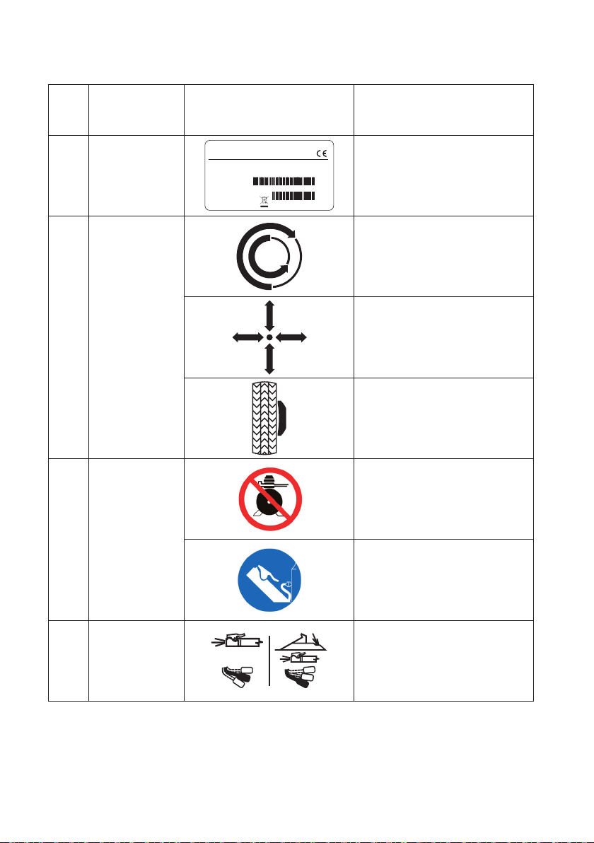
12. Do NOT mount or inate tyres that are cut, damaged, decayed or worn. Do NOT
mount tyres on damaged, bent, rusted, worn, warped or deformed rims.
13. Should the tyre get damaged during the mounting phase, do not try to complete the
mountingoperation.Removeit, takeit awayfrom theservicearea andmark itas damaged.
14. Inate tyres in gradual steps, while continuously monitoring the pressure and obser-
ving the tyre itself, the rim and the bead. NEVER exceed the pressure limits indicated
by the manufacturer.
15. The internal parts in this equipment could create contacts or sparks if exposed to
ammable vapours (petrol, paint thinners, solvents, etc.). Do not install the machine in
a narrow area or position it below oor level.
16. Do not operate the machine while under the inuence of alcohol,
medicines and/or drugs. If you are taking prescription or non-prescription
medicines, contact a physician to be aware of the side effects that they
might have on the ability to operate the machine safely.
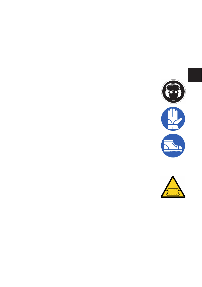
17. Always use OSHA, CE approved and authorised personal protective
equipment (PPE) or equipment with equivalent certications while ope-
rating the machine. Consult your supervisor for additional instructions.
18. Do not wear jewellery, watches, loose clothing, ties and tie up long
hair before using the machine.
19. Wear protective, non-slip footwear while using the tyre changer.
20. While positioning, lifting or removing wheels from the tyre changer,
wear an appropriate back support and use a correct lifting technique.
21. Only appropriately trained personnel can use, service and repair the
machine. Repairs must only be performed by qualied personnel. Ma-
nufacturer technicians are the most qualied individuals. The employer
must determine if an employee is qualied to carry out any machine repair
safely if the operator has attempted to make the repair.
22. Before starting the machine, the operator must pay close attention to the warnings
of the adhesive labels afxed to the equipment.
23. Disconnecting the pneumatic supply, both due to non-use or to
maintenance of the machine or the pneumatic system of the workshop,
can leave pneumatic actuators under pressure. Discharge the machine
pneumatic system using the controls on the actuators.
24. Use a lifting device if the wheel weighs more than 10 kg, with a lifting
frequency of more than 20 wheels/hour.

10 User’s manual
1.2.b.LABELSPLACEMENT
No. PartNumber Drawing Description
01 Code
Serial N.
X-XXXXXXXX/XX - XX
XXXXXXXXX
ANNO DI COSTRUZIONE /
MANUFACTURED
Mod.
V
A
kW
Hz
Ph
bar/psi
LABEL, MODEL SERIAL
NUMBER
02 000101100
LABEL, ROTATION
TURNTABLE
LABEL, TURNTABLE OPE-
NING/CLOSING
LABEL, BEAD BREAKER
ACTIVATION
03 000102700
LABEL, DO NOT CONNECT
PRESSURIZED DEVICES
LABEL, DOYFE UNION
04 000105200 LABEL, INFLATION PEDAL

User’s manual 11
EN
05 000102800
LABEL, OPERATING PRES-
SURE
LABEL, DANGER - PRES-
SURISED CONTAINER
06 000103200 LABEL, HAND CRUSHING
HAZARD (TURNTABLE)
07 000103300 LABEL, HAND CRUSHING
HAZARD (BEAD BREAKER)
08 000103400 LABEL, LEG CRUSHING
HAZARD (BEAD BREAKER)
09 000102900 LABEL, RISK OF INJURY,
REAR POLE
10 000103100
LABEL, DANGER - TOOL
HEAD
LABEL, DANGER - TURN-
TABLE
11 4-600990
NEVER EXCEED 40
PSI WHILE SEATING
BEADS.
NEVER
EXCEEDTIRE
MANUFACTURER
RECOMMENDED
PRESSURE AFTER
SEATINGBEADS.
NEVER LEAN OR
REACHOVERTIRE
OR RIMDURING
INFLATION.
WHEN INFLATINGTIRES MAKE SURE THAT:
1) The rim diameter matches the tire diameter.
2) The rim or tire are not defective.
3) The beads are not seated exceeding recommended
pressure.
4) The tire is not inflated beyond the tire manufacturers
instructions.
5) The operator follows proper safety rules.
IMPORTANT SAFETY RULES
A) Only trained operators should use this machine.
B) Read and understand the instruction manual before operating this
machine.
C) Wear eye protection.
D) Keep hands and clothing away from moving parts.
E) Service machine regularly as outlined in the instruction manual.
F) Remove all air from tire before loosening beads. Remove valve
core.
G) Remove all wheel weights from rim before mounting or
demounting to preventdamage.
H) Always use a proper bead lubricant before mounting, demounting
and seating beads.
E) Always verify that the tire and the rim are exactly the same bead
diameter.Tire size is molded into the side wall. Rim size is
stamped into the rim.Never mount a tire on a rim if the bead
diameter can not be identified.
F) Inspect the tire and rim carefully for defects. Do not mount the tire
if any defects are found.
G) Seat beads and inflate the tire with short bursts of air while
continuously checking the air pressure.
H) Stand away from the tire and wheel when inflating. Never lean or
reach over the tire during inflation. Keep area clear of by standers.
I) Never exceed the tire manufacturer's recommended maximum air
pressure. Tirescan burst when inflated beyond specified limits.
WARNING Donot mount any tire unless the tire size
(molded in to the side wall) matches the rim
size (stamped into the rim) exactly!
NEVER ATTEMPTTO MOUNT:
16" tires on 16.5" rims
15.5" tires on 16" rims
15" tires on 15.5" rims
15" tires on 390mm rims
14" tires on 365mm rims
WARNING
LABEL, DANGER OF INFLA-
TION

12 User’s manual
12 4-603202 LABEL, RISK OF EXPLO-
SION
13 000103900 LABEL, EARTH GROUND
TERMINAL
14 000106200 LABEL, ROTATION DIREC-
TION
15 425211A LABEL, DANGER OF ELEC-
TRIC SHOCK
17 4-604278 LABEL, LOGO
18 4-600991
NEVER EXCEED 40 PSI
WHILE SEATING
BEADS.
NEVER EXCEED TIRE
MANUFACTURER
RECOMMENDED
PRESSURE AFTER
SEATING BEADS.
NEVER LEAN OR
REACH OVER TIRE OR
RIM DURING
INFLATION.
Bleed air
pressure
from tire
before
breaking
beads.
Keep
hands
away
from
rotating
parts
Keep
legs
away
from
bead
breaker
WARNING
WARNING
LABEL, VARIOUS RISK
19 4-600992
CAUTION!
RISK OF ELECTRIC SHOCK.
DO NOT OPEN COVER
WARNING
TO REDUCE THE RISK OF ELECTRIC SHOCK DO
NOT EXPOSE THIS TIRE CHANGER TO RAIN.
WATER OR WET LOCATIONS.
WARNING
THIS TIRE CHANGER DOES NOT CONTAIN USER
SERVICEABLE PARTS. DO NOT OPEN COVER. DO
NOT TAMPER WITH COMPONENTS. FAILURE TO
COMPLY MAY CAUSE SERIOUS INJURY OR DEATH
TO OPERATOROR BYSTANDERS.
LABEL, ELECTRIC RISK
20 4-600993
WARNING!
TO PREVENT
ACCIDENTS AND INJURIES
READ INSTRUCTIONS
BEFORE OPERATING
SAFETY INFORMATIONS
•Before using this machine read and understand all warnings
and the Instruction Manual provided with this tire changer.
•Follow all warnings and instructions during use.
•Do not cover warnings and/or instructions.
•Unreadable and missing warning labels must be replaced
immediately. Don't use the tire changer if one or more labels
are unreadable or missing.
LABEL, INFORMATION
21 4-602033
WARNING
LOCKED
UNLOCKED
DO NOT
FORCE LABEL, UNLOCKING CON-
TROL PLATE

User’s manual 13
EN
1.2.c. HAZARD LABELS KEY
part n. 000102800
LABEL, DANGER - PRESSURISED
CONTAINER
part n. 000103200
LABEL, HAND CRUSHING HA-
ZARD (TURNTABLE)
part n. 000103300
LABEL, HAND CRUSHING HA-
ZARD (BEAD BREAKER)
part n. 000103400
LABEL, LEG CRUSHING HAZARD
(BEAD BREAKER)
part n. 000102900
LABEL, RISK OF INJURY, REAR
POLE
part n. 000103100
LABEL, DANGER - TOOL HEAD
LABEL, DANGER - TURNTABLE
part n. 425211A
LABEL, DANGER OF ELECTRIC
SHOCK
part n. 4-603202
LABEL, RISK OF EXPLOSION
part n. 000103900
LABEL, EARTH GROUND TERMI-
NAL

14 User’s manual
part n. 446237
LABEL, EARTH GROUND TERMI-
NAL
NEVER EXCEED 40
PSI WHILE SEATING
BEADS.
NEVER
EXCEEDTIRE
MANUFACTURER
RECOMMENDED
PRESSURE AFTER
SEATING BEADS.
NEVER LEAN OR
REACH OVERTIRE
OR RIM DURING
INFLATION.
WHEN INFLATINGTIRES MAKE SURE THAT:
1) The rim diameter matches the tire diameter.
2) The rim or tire are not defective.
3) The beads are not seated exceeding recommended
pressure.
4) The tire is not inflated beyond the tire manufacturers
instructions.
5) The operator follows proper safety rules.
IMPORTANT SAFETY RULES
A) Only trained operators should use this machine.
B) Read and understand the instruction manual before operating this
machine.
C) Weareye protection.
D) Keephands and clothing away from moving parts.
E) Service machine regularly as outlined in the instruction manual.
F) Remove all air from tire before loosening beads.Remove valve
core.
G) Remove all wheel weights from rim before mounting or
demounting to prevent damage.
H) Alwaysuse a proper bead lubricant before mounting, demounting
and seating beads.
E) Always verify that the tire and the rim are exactly the same bead
diameter.Tire size is molded into the side wall. Rim size is
stamped into the rim. Never mount a tire on a rim if the bead
diameter can not be identified.
F) Inspect the tire and rim carefully for defects. Do not mount the tire
if any defects are found.
G) Seat beads and inflate the tire with short bursts of air while
continuously checking the air pressure.
H) Stand away from the tire and wheel when inflating. Never lean or
reach over the tire during inflation. Keep area clear of by standers.
I) Never exceed the tire manufacturer's recommended maximum air
pressure. Tires can burst when inflated beyond specified limits.
WARNING
Do not mount any tire unless the tire size
(molded in to the side wall) matches the rim
size (stamped into the rim) exactly!
NEVER ATTEMPT TO MOUNT:
16" tires on 16.5" rims
15.5" tires on 16" rims
15" tires on 15.5" rims
15" tires on 390 mm rims
14" tires on 365 mm rims
WARNING
part n. 4-600990
LABEL, DANGER OF INFLATION
NEVER EXCEED 40 PSI
WHILE SEATING
BEADS.
NEVER EXCEED TIRE
MANUFACTURER
RECOMMENDED
PRESSURE AFTER
SEATING BEADS.
NEVER LEAN OR
REACH OVER TIRE OR
RIM DURING
INFLATION.
Bleed air
pressure
from tire
before
breaking
beads.
Keep
hands
away
from
rotating
parts
Keep
legs
away
from
bead
breaker
WARNING
WARNING
part n. 4-600991
LABEL, VARIOUS RISK
CAUTION!
RISK OF ELECTRIC SHOCK.
DO NOT OPEN COVER
WARNING
TO REDUCE THE RISK OF ELECTRIC SHOCK DO
NOT EXPOSE THIS TIRE CHANGER TO RAIN.
WATER OR WET LOCATIONS.
WARNING
THIS TIRE CHANGER DOES NOT CONTAIN USER
SERVICEABLE PARTS. DO NOT OPEN COVER. DO
NOT TAMPER WITH COMPONENTS. FAILURE TO
COMPLY MAY CAUSE SERIOUS INJURY OR DEATH
TO OPERATOROR BYSTANDERS.
part n. 4-600992
LABEL, ELECTRIC RISK

User’s manual 15
EN
01
05
02
06
07
08
18
09
14
21
21
04
12
11A
11B
10
17
16
15
19
03
20

16 User’s manual
1.2.d.
ELECTRICAL AND PNEUMATIC CONNECTIONS
WARNING
Agoodearthconnectionisessentialforcorrectoperationofthemachine.
The electric connection used must be su-
itably sized:
• to the electric power absorbed by the
machine, indicated on its data plate (Fig. 1);
• to the distance between the operating machine
andthepowersupplyconnectionpoint,toensure
that the voltage drop under full load does not
exceed 4% (10% during start-up) of the rated
voltage value specied on the plate
- The user must:
• t a power plug in compliance with current regulations
on the power supply lead;
• connect the machine to its own electrical connection
- A, Fig. 2 - equipped with a differential automatic
circuit breaker with 30mA sensitivity;
• install protection fuses on the power line that are
suitably sized in accordance with the indications
provided on the machine data plate (Fig.1);
• connect the machine to an industrial socket; the
machinemustnotbeconnectedtodomesticsockets.
Make sure that the available pressure and performance
of the compressed air system are compatible with what
is necessary for correct machine operation - see the
section “Technical data”. For the correct operation of
the machine, the pneumatic supply line must provide a
pressure range from a minimum of 8 bar to a maximum
of 16 bar.
WARNING
Forcorrectequipmentoperation,theairproducedmustbesuitablytreated(not
above5/4/4accordingtostandardISO8573-1).
Check that the lubrication cup (B, Fig. 2a) contains lubricating oil; top up is necessary.
Use SAE20 oil.
Code
Serial N.
X-XXXXXXXX/XX - XX
XXXXXXXXX
ANNO DI COSTRUZIONE /
MANUFACTURED
Mod.
V
A
kW
Hz
Ph
bar/psi
1
2
A
B

User’s manual 17
EN
Thepneumaticsupply inletpoint,in theworkshopline,
must be equipped with a pneumatic supply shut-off
valve, placed upstream the lter/regulator unit sup-
plied with the machine (B Fig. 2a).
DANGER
Beforeproceedingwiththeelectricaland
pneumaticconnectionandwheneverthe
electrical and pneumatic power supply
isrestored,makesurethatthemachine
isinthecongurationdescribedbelow:
-pedalACOMPLETELYLOW(turntable
closed).
A
1.2.e TECHNICAL DATA
- Table top clamping capacity:
• inside clamping .............................................................................................. 14”-27”
• outside clamping............................................................................................ 11”-24”
- Rim width:.............................................................................................405 mm (15,5”)
- Maximum tyre diameter:........................................................................1120 mm (44”)
- Bead breaking pressure: .................................................................................2900 Kg
- Air pressure: ....................................................................................................8-10 Bar
- Motor electrical features:
• 1ph version - 2 speed 230V - 50Hz (Motoinverter).......................................0.75 kW
- Weight ................................................................................................................260 kg
- Weight of electrical/ electronic components:.....................................................11,5 kg
-
Noise level: A-weighted sound pressure level (LpA) at the working position
... < 70 dB (A)
Motor Rating Kw rpm
200-230V / 1ph / 50Hz (Motoinverter) _ 2 speed 0,75 7,5 - 18
B
2a

18 User’s manual
The noise levels indicated correspond to emission levels and do not necessarily represent
safe operating levels. Although emission levels and exposure levels are connected,
this relation cannot be used as a safe parameter to determine whether or not further
precautions are necessary. The noise level to which the operator is exposed to depends
on a number of factors, such as duration of exposure, characteristics of the workplace,
other sources of noise etc. Permissible noise exposure levels may also vary from country
to country. In all cases, this information will enable machine users to better assess the
danger and risks involved.
1.2.f.
AIR PRESSURE
DANGER
•RISKOFEXPLOSION
•Neverexceedtyrepressurerecommendedbytyre
manufacturer.
•Alwaysmatchthetyreandrimdimensions.
•Takecaretoavoidanydamagetothetyre.
•Duringinflation,keepoutsidetheverticalcylinder
areaoccupiedbythewheel.
The machine is equipped with an internal pressure limiting valve to minimize the risk of
over inating the tyre.
1. Never exceed these pressure limitations:
• The supply circuit pressure (from the compressor) is 220psi(16bar).
• The operating pressure (indicated on the regulator) is 150psi(10bar).
• The tyre ination pressure (displayed on the pressure gauge) must never exceed the
pressure indicated by the manufacturer on the sidewall of the tyre itself.
2. Activate the air ination jets only when inserting the bead.
3. Fully bleed air pressure system before disconnecting power supply line or other
pneumatic components. Air is stored in a reservoir to operate the ination jets.
4. Activate the air ination jets only if the rim is correctly clamped on the tyre changer (if
required) and the tyre is completely mounted.

User’s manual 19
EN
1.3.
ADDITIONAL RIM/TYRE INFORMATION
WARNING
Wheelsequippedwithpressuresensorsandspecialrimsortyrescouldrequire
particularworkprocedures.Consultwheelsandtyremanufacturer’sservice
manuals.
1.4. INTENDED MACHINE USE
This machine must only be used to demount and mount vehicle tyres from/on the rims,
using the provided tools. Any other use is improper and may result in injury.
1.5. PERSONNEL TRAINING
1. Employers are responsible for providing a training program for all employees who
work on the wheels concerning the hazards deriving from maintenance and the safety
procedures to be observed. Service or maintenance refer to mounting and demounting
wheels and all the correlated activities, such as ination, deation, installation, removal
and handling.
• Employers are required to make sure that operators do not work on the wheels unless
they have received suitable training regarding the correct maintenance procedures for
the type of wheel being serviced and the operative safety procedures.
• Information to be used for the training program includes, as a minimum, the information
contained in this manual.
2. Employers are required to make sure that every employee demonstrates and main-
tains the ability to work on the wheels safely, including the performance of the following
activities:
• Demounting of tyres (including deation).
• Inspection and identication of the rim wheel components.
• Tyre mounting.
• Use of any restraint device, cage, barrier, or other systems.
• Handling of wheels with rims.
• Tyre ination.
• Move away from the tyre changer while inating the tyre and do not lean over to inspect
the wheel during ination.
• Wheel installation and removal.
3. Employers must evaluate the ability of their employees to carry out these tasks and
work on the wheels in absolute safety and must provide additional training as required
to make sure that all employees maintain their skills.

20 User’s manual
1.6. PRELIMINARY CHECKS
Before starting to work, carefully check that all machine components, particularly rubber
or plastic parts, are in place, in good condition and operate correctly. If the inspection
reveals any damage or excessive wear, no matter how slight, immediately replace or
repair the component.
Walk around the machine to ensure that all components are in good condition and ope-
rational, and that there are no foreign objects or debris (rags, tools, etc.…) in or near
the machine which could affect its operation.
These checks must be carried out:
• Before starting the machine.
• At regular time intervals.
• After any modication or repair.
The machine may only be started after this pre-use check is successfully completed. Do
not use the machine if it is placed out of service for tune up, maintenance, lubrication, etc.
1.7. DURING USE
If strange or unusual noises are heard or any unusual vibration is detected, if a compo-
nent or system is not operating correctly or if you observe anything unusual, immediately
stop using the machine.
• Identify the cause and implement all the necessary corrective measures.
• Contact your supervisor if necessary.
Make sure that all other people are standing at least 6 metres (20 feet) from the machine.
To switch off the machine in case of emergency:
• disconnect the power supply plug;
• interrupt the compressed air supply by disconnecting the supply pipe.
WARNING
Theinterruptionofthepneumaticsupplycanleavesomeactua-
torsunderpressureasindicatedbythepictogramafxedon
the machine.
Usethecontrolstobleedtheairtheycontain.
1.8. OPTIONAL ACCESSORIES
Contact the sales network to nd all the optional accessories suitable for this machine.
Table of contents
Languages:
Other CEMB Tyre Changer manuals
Popular Tyre Changer manuals by other brands

GIULIANO
GIULIANO S224 Installation, operation and maintenance guide

Coats
Coats Rim Clamp APX80E operating instructions

WilTec
WilTec 61909 Operation manual

HENNESSY INDUSTRIES
HENNESSY INDUSTRIES Coats CHD-4730-4730W Operating and maintenance instructions

Coats
Coats 7050 manual

Fasep
Fasep RGU300.ECO Instruction booklet