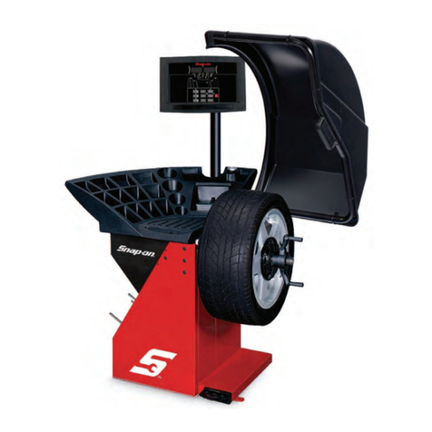
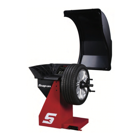
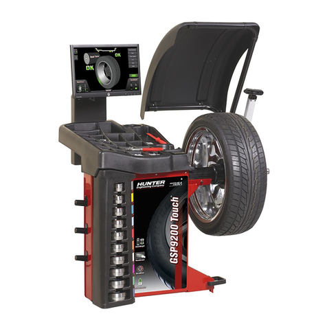
Snap-On EEWB304B User manual

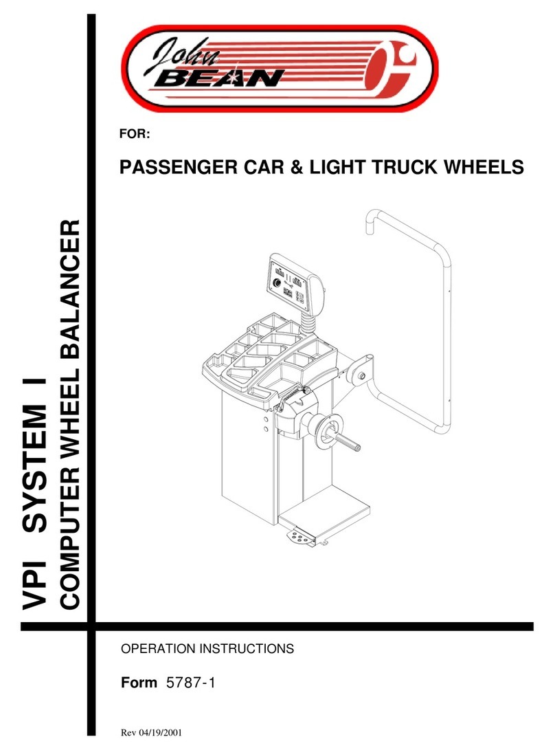
EEWB304B
COMPUTER WHEEL BALANCER
FOR:
PASSENGER CAR & LIGHT TRUCK WHEELS
OPERATION INSTRUCTIONS
Form ZEEWB304B
®®
®®
®


SAFETY INFORMATION
For your safety, read this manual thoroughly
before operating the EEWB304B Wheel Balancer
The Model EEWB304BWheel Balancer isintended foruse by properlytrained automo-
tive technicians. The safety messages presented in this section and throughout the
manual are reminders to the operator to exercise extreme caution when servicing tires
with these products.
There are many variations in procedures, techniques, tools, and parts for balancing
tires, as well as the skill of the individual doing the work. Because of the vast number
of wheel and tire applications and potential uses of the product, the manufacturer can-
not possibly anticipate or provide advice or safety messages to cover every situation.
It is the automotive technician's responsibility to be knowledgeable of the wheels and
tires being serviced. It is essential to use proper service methods in an appropriate and
acceptable manner that does not endanger your safety, the safety of others in the work
area or the equipment or vehicle being serviced.
It is assumed that, prior to using the Model EEWB304B Wheel Balancer, the operator
has a thorough understanding of the wheels and tires being serviced. In addition, it is
assumed he has a thorough knowledge of the operation and safety features of the
rack, lift, or floor jack being utilized, and has the proper hand and power tools neces-
sary to service the vehicle in a safe manner.
Before using the Model EEWB304B Wheel Balancer, always refer to and follow the
safety messages and service procedures provided by the manufacturers of the equip-
ment being used and the vehicle being serviced.
IMPORTANT !! SAVE THESE INSTRUCTIONS -- DO NOT DISCARD !!
WARNING
· Wheel balancers can cause flying particles
Wear safety glasses. (user and bystanders)
Flying material can cause injury.
WARNING
·Moving components.
Keep self and tools clear of moving parts.
Moving components can cause injury.

Page 2
IMPORTANT SAFETY INSTRUCTIONS
When using this equipment, basic safety precautions should always be followed,
including the following:
1. Read all instructions.
2. Donotoperateequipmentwithadamagedpowercordoriftheequipmenthasbeen
damaged - until it has been examined by a qualified authorized service technician.
3. Always unplug equipment from electrical outlet when not in use. Never use the
cord to pull the plug from the outlet. Grasp plug and pull to disconnect.
4. To reduce the risk of fire, do not operate equipment in the vicinity of open
containers of flammable liquids (gasoline).
5. Keephair,loosefittingclothing,fingersandallpartsofthebodyawayfrommoving
parts.
6. Adequate ventilation should be provided when working on operating internal
combustion engines.
7. To reduce the risk of electric shock, do not use on wet surfaces or expose to rain.
8. Do not hammer on or hit any part of the control panel with weight pliers.
9. Do not allow unauthorized personnel to operate the equipment.
10. Do not disable the hood safety interlock system or bypass the intended operation.
11. Use only as described in this manual. Use only manufacturer’s recommended
attachments.
12. Always securely tighten the wing nut before spinning the shaft.
13. ALWAYS WEAR SAFETY GLASSES. Everyday eyeglasses only have impact
resistant lenses, they are NOT safety glasses.
14. Balancer is for indoor use only.
SAVE THESE INSTRUCTIONS

Page 3
Snap-onEEWB304B OperatorsManual
TABLE OF CONTENTS
General Safety Instructions Page 2
1.0 Introduction Page 4
1.1 Safety Notice Page 4
1.2 Balancer Application Page 4
1.3 Specifications Page 5
1.4 Balancer Features Page 5
1.5 Standard Accessories Page 6
1.6 Optional Accessories Page 6
1.7 Dimensions Of The Machine Page 7
1.8 Installation Area Page 7
1.9 Installation Instructions Page 7
2.0 Balancer Assembly Page 7
2.1 Shaft Adapter Installation Page 7
2.2 Wheel Guard Installation Page 8
2.3 Electrical Installation Page 8
3.0 Terminology Page 9
4.0 Balancer Operation Page 10
4.1 Inspection Check list Page 10
4.2 Wheel Mounting Page 10
4.2.1 Mounting of Standard Wheels Page 10
4.2.2 Mounting of Light Truck Wheels Page 11
4.3 Mode Selection Page 11
4.3.1 Weight Placement Modes Page 11
4.4 Selecting Operator Preferences Page 12
4.4.1 FineBalance Mode Page 12
4.4.2 Ounce /Grams Conversion Page 12
4.4.3 Inch/MillimeterConversion Page 12
4.4.4 OperatorA/B Selection Page 12
4.5 Entering Rim Parameters Page 13
4.5.1 Distance and Diameter Entry Page 13
4.5.2 Rim Width Entry Page 13
4.5.3 Manual Parameter Entry Page 13
4.6 Correcting the Imbalance Page 14
4.7 Verifying Results Page 14
4.8 Vibration Problems Page 14
5.0 Matching Program Page 15
6.0 Optimization Program Page 17
7.0 Alu-S Program Page 18
8.0 SpokeMode Page 19
9.0 Split Weight Mode Page 20
10.0 UserCalibration Page 21
11.0 Calibration of the SAPE Page 22
11.0 Explanation of “P” Codes Page 23
12.0 Maintenance Page 23
13.0 TroubleShooting Page 22

Page 4
1.0 INTRODUCTION
Congratulations on purchasing the EEWB304B computer wheel balancer. This wheel balancer is de-
signed for ease of operation, accuracy, reliability and speed. With a minimum of maintenance and care
your wheel balancer will provide many years of trouble-free operation.
Instructions on use, maintenance and operational requirements of the machine are covered in this
manual.
STORE THIS MANUAL IN A SAFE PLACE FOR FUTURE REFERENCE.
READ THIS MANUAL THOROUGHLY BEFORE USING THE MACHINE.
1.1 SAFETY NOTICE
This manual is a part of the balancer product.
Read carefully all warnings and instructions of this manual since they provide important information
concerning safety and maintenance.
1.2 BALANCER APPLICATION
TheSnap-onwheelbalancermodelEEWB304B isintendedtobeusedasadevicetobalancecar, and
light truck wheels within the following range:
Maximum wheel diameter : 44” (1117mm)
Maximum wheel width : 16” (530mm)
Maximumwheelweight : 130lbs (58.5 kg)
This device is to be only used in the application for which it is specifically designed.
Any other use shall be considered as improper and thus not reasonable.
The manufacturer shall not be considered liable for possible damages caused by improper, wrong or
non reasonable use.

Page 5
Snap-onEEWB304B OperatorsManual
1.3 EEWB304B SPECIFICATIONS
Computerized digital wheel balancer for car, light truck
wheels.
Weight Imbalance Accuracy .10 oz / 2 grams
Weight Placement Resolution ± .7 degrees
Weight Imbalance Resolution:
Roundoff Mode .25 oz / 5 grams
Non-Roundoff Mode .05 oz / 1 gram
Max. Shaft Weight Capacity 133 lbs / 60 kg
Max.Tire Diameter 44" / 1117 mm
Rim Width Capacity 3.0"-25" / 76 mm - 508 mm
Max. Tire Width 20” / 508 mm
Rim Diameter Capacity 8"-25" / 152 mm-635 mm
Balancing Cycle Time. 7 seconds or less
Shaft Speed at calculation <100 RPM
Electrical 115V, 1ph, 50-60Hz, 15A
Required Work Area 62” x 64.5” (1575 x1638
mm)
Shipping Weight, complete 325 lbs/147kg
ShippingDimensions 52.75”h 41.5”w 37”d
Machine Dimensions 39”h 39”w 22”d
Actual Weight with Accessories 251 lbs / 113 kg
Operating Temperature Range 32-122F / 0-50C
1.4 FEATURES
ACCURACY
• Weight placement accuracy to as low as ± .7°
• Weight imbalance accuracy to 2 grams.
• Self test check with every power up cycle.
• Fast operator calibration.
• Pre-programmed Error Codes indicate procedural
errors or safety concerns.
SPEED and DURABILITY
• Automatic distance/diameter entry. Simply touch the
distancearm to the wheel, the distance anddiameter
parameters are automatically entered.
• Quickclamp speednut reduces wheelmounting time.
• Capturedback spring eliminateshavingto handle the
backing spring.
• Quick cycle time.
• Automatic recalculation if weight positions are
changed. No need for re-spinning the wheel.
• Common40 mm diameter mounting shaft.
• Weight pocket storage tray.
• Easy-to-Read Data display.
• Easy weight tray access.
SOFTWARE VERSATILITY
• Both dual weight Dynamic and single weight Static
capability.
• MatchBalance program forreducing weight required.
• Built-in spin counter for monitoring balancer
productivity.
• Service code access to all Balancer electronic func-
tions for fast, easy diagnosis.
• Operator selectable roundoff mode.
• 5 Aluminum Modes
• Alu-S mode
• Hidden Weight (Spoke) mode
• Split weight mode

Page 6
1.5 STANDARD ACCESSORIES
Centering Cones and Accessories
For centering of wheels with center holes
1 EAM0003J08A Cone,85-132 mm /3.36”-5.2”
2 EAM0003J07A Cone, 71-91mm/2.8”-3.6”
3 EAM0003J06A Cone, 56-84mm/ 2.18”-3.3”
4 EAM0003J05A Cone, 43-64 mm / 1.7” - 2.5”
5 EAM0058D07A Cup- Pressure
6 EAC0058D15A RubberRing Protector
7 EAA0263G66A Quick Nut
7A EAC0058D08A Disk - Small Pressure
8 EAM0005D40A Weight- Calibration
9 EAM0021D90A 40 mm Stub Shaft
10 EAA0247G21A Caliper - Rim Width
11 EAC0060G02A Flange -Cover,Hook
12 EAM0006G01A Pin - Accessory
* EAM0005D34A FasteningRod for shaft
* notshown
Figure 1
Figure 2
1.6 OPTIONAL ACCESSORIES
Weight Pliers P/N WWPR13A (Figure3).
Versatile weight hammer/plier. In addition to ham-
mering on weight and used weight removal, the
WWPR13A canbe used to reshape worn weight clips
and trim weight to size.
PRE-INSTALLATION CONSIDERATIONS
Figure 3

Page 7
Snap-onEEWB304B OperatorsManual
1.7 DIMENSIONS OF THE MACHINE
Figure 4 - Footprint dimensions.
1.8 REQUIRED INSTALLATION AREA
Makesure that from the operatingpositionthe user can
see all of the machine and the surrounding area.
The operator should prevent non authorized persons
and/or objects from entering the area which may cre-
ate potential hazards.
Themachineshould be installed on a stable level floor.
Do not install the machine on a uneven floor.
If the balancer is to be installed on a raised floor, the
floor must have a capacity of at least 110lbs per sq ft.
(5000 N/m² - 500 kg/m²).
It is not required to secure the machine to the floor.
Install the machine in a dry, covered area.
Theinstallationof the machine requires a working area
of at least 62” x 64.5” (1575 x 1638 mm) (Figure5).
Figure5- Recommended workarea
1.9 INSTALLATION INSTRUCTIONS
CAUTION! CAREFULLY REMOVE THE BALANCER
FROM THE PALLET.
THE UNIT IS HEAVY AND THE WEIGHT IS NOT
EVENLY DISTRIBUTED.
DO NOT LIFT THE BALANCER BY THE SHAFT.
DROPPING THE UNIT MAY CAUSE PERSONAL IN-
JURY OR EQUIPMENT DAMAGE.
2.0 BALANCER ASSEMBLY
2.1 MOUNTING THE SHAFT ADAPTER
A. Mount the threaded shaft onto the arbor of the bal-
ancer. Tighten firmly using the supplied wrench. (Fig-
ure 6).
IMPORTANT! - CHECK THAT THE SURFACES ARE
PERFECTLY CLEAN AND NOT DAMAGED. AN IN-
CORRECT MOUNTING MAY RESULT IN SIGNIFI-
CANTIMBALANCE.
Figure 6

Page 8
B. Remove the hardware that secures the machine to
thepallet andslide the balanceronto thefloorwhere itis
to be installed.
C. Install the accessory pins (Figure 7).Tighten firmly.
Figure 7
D. Place cones and other accessories onto the acces-
sory pins.
2.2 HOOD GUARD INSTALLATION
The safety hood guard is standard equipment and
must be installed prior to use.
Refer to Figure 8 for hood guard installation.
Parts Required:
(1) Hood Guard Assembly
(1) 3/8” - 16 x 2” HHCS
(1) 3/8” x 16 Keps
Position the hood guard in the raised (up) position.
Slide the hood guard support tube over the frame pivot
shaftprotruding from the rightsideof the balancer cabi-
net.
Line up the mounting holes in both the pivot shaft and
theguardsupporttube. Securethe guardwith 3/8”hard-
ware.
Figure 8
2.3 ELECTRIC INSTALLATION
ANY ELECTRICAL WIRING MUST BE PER-
FORMED BY LICENSED PERSONNEL.
ALL SERVICE MUST BE PERFORMED BY AN
AUTHORIZED SERVICE TECHNICIAN.
Check on the plate of the machine that the electrical
specifications of the power source are the same as the
machine. The machine uses 115VAC, 50-60Hz, 1Ph,
8.0 Ampere. 230VAC units are available if required.
NOTE:
Any electrical outlet installation must be verified
by a licensed electrician before connecting the bal-
ancer.
NOTE:
This machine performs a self-test routine on start-
up. There will be a delay of several seconds before
the display is activated.

Page 9
Snap-onEEWB304B OperatorsManual
3.0 TERMINOLOGY
Figure 9
Before using the wheel balancer it is suggested that
you become familiar with the terminology of the
machine’s components. Refer to Figures 9 and 10.
Display Features:
1. Inner Plane Imbalance Value Display
2. Inner Plane Imbalance Position Indicator
3. Width And Message Display
4. Outer Plane Imbalance Position Indicator
5. Outer Plane Imbalance Value Display
6. Display All Parameters Button
7. Normal-Fine Mode Button
8. Multiple Operator Select Button
9. “P” Codes Button
10. Mode Select Button
11. Balance Mode Indicator
12. Rim Width/Offset/Function Knob
13. Cancel/Stop Button
14. Manual Diameter Button
15. Rim Offset Button
16. Alu-S/Spoke Mode Button
17. Enter Button
Cabinet Features:
18. Wheel Guard
19. Wheel Weight Tray
20. Rim Width Caliper Storage
21. Cones/Accessories Storage Location
22. Foot Operated Shaft Lock
23. Arbor - Shaft Adapter
24. Semi-Automatic Parameter Arm (SAPE)
Figure 10

Page 10
4.0 OPERATION OF THE BALANCER
WARNING: Foroperatorsafety please read
and follow the precautions outlined on
pages 1 and 2 of this manual.
NOTE: Read all instructions before pro-
ceeding with operation of the balancer.
All balancer functions are input into the main computer
through the large easy to read touch panel. Although
each wheel tire assembly differ in some ways all bal-
ancingjobsrequire basically the same procedure. The
order of events to take place are:
1. Inspection of the wheel/tire assembly
2. Mounting wheel onto shaft or adapter
3. Selection of Balancing Mode and Preferences
4. Entry of wheel parameters
5. Spinning the wheel
6. Applying the recommended weight
7. Check spin if desired
8. Dismounting the wheel
The following operation instructions will follow the ba-
sic outline above.
4.1 CHECK LIST - INSPECTION
Observe Before Balancing Wheel
1.Checkforproperairpressure. Ifnotcorrect,inflateto
correct pressure.
2. Check for any foreign material inside tire. If present,
remove before balancing tire.
WATER IS FOREIGN MATERIAL!
3.Removeoldweights— oldweights maybe improper
value or in wrong location.
4.Besuretireand wheel are free of excessive dirt, rust
andlarge stones.Use wirebrush onbackside ofwheel
if necessary.
4.2 WHEEL MOUNTING
Nearlyallstandardwheelsandmanyalloywheelshave
accurately machined center holes, and they should be
mounted with center cones. Accurate balancing de-
pends on accurate mounting of the wheel and correct
seatingoftheconeinthepilothole.Insurethatthewheel
is centered on the shaft exactly as it will be mounted to
the vehicle.
Beforestarting anybalancing procedureitis veryimpor-
tant that the wheel is mounted on the machine with the
properadaptors.Anincorrectcentering of thewheelwill
result inconsiderableimbalance.
Thereare many types of wheels andSnap-on supplies
adaptors of good quality and durability for the large
majority.Howeverifyoumeetspecialwheels whichmay
require a specific adaptor, call your authorized Snap-
on distributor.
Rims may be divided into these major groups:
1. Car rims with a true center hole.
2. Car rims without a center hole.
3. Car rims with an untrue center hole.
4. Light truck rims.
4.2.1 Standard Wheels (back cone mount)
Mount the wheel as detailed below in Figure 11:
1. Mount proper cone against spring plate.
2. Mount wheel on shaft in the same manner as you
would on the car.
3. Mount pressure cup on shaft and place against
outside of wheel, follow with the Quick-nut.
4. Tighten Quick-nut securely with both hands. To
operate the Quick-nut pull the lock-unlock lever
(Figure 12). Slide the Quick-nut on the threaded
shaft. When in contact with the rim, release the
unlock lever and tighten firmly. To assist in
centering the wheel properly, rotate the wheel on
the shaft while tightening the quick nut.
Figure 11

Page 11
Snap-onEEWB304B OperatorsManual
FAILURE TO TIGHTEN WING NUT SECURELY
MAYRESULTINSERIOUSPERSONALINJURY.
DO NOT USE A HAMMER TO TIGHTEN THE
QUICK NUT.
TO RELEASE THE QUICK NUT, UNSCREW A
FEW TURNS TO REDUCE THE AXIAL PRES-
SURE,THEN PRESS THE UNLOCK LEVERAND
SLIDE AWAY FROM THE SHAFT.
5.Check thatthe wheelrotates trueby turningthewheel
several revolutions while noting any excessive runout.
4.2.2 CENTERING LIGHT-TRUCK WHEELS
Anoptional offsetspacermay berequired for somelight
truck wheels and reverse-offset wheels that must be
moved away from the balancer mounting flange. The
extension adaptor is often used with the 5-1/4 inch di-
ameter light truck cone.
Install the spacer on the mounting flange, then mount
the wheel, using the front cone method (Figure 13)
Figure 13
4.3 MODE SELECTION
The majority of balancing takes place in the default 2-
plane dynamic mode which is displayed as "2 PL"
(location1,seefigure14). Hammer-onclipweightswill
beplaced onbothinside andoutsideof the rimedge. If
required,selectan optional weight placement mode by
pressing the Mode button until the appropriate place-
ment mode is displayed.
4.3.1 WEIGHT PLACEMENT MODES
Before spinning the wheel (although it may be done af-
terwards) choose the appropriate balancing mode for
thewheel.Toselectthevariousplacement modespress
the Mode button (#10 Figure14) until placement LEDs
indicate desired placement position.
The balancing modes available are:
A. DYNAMIC (twoplanes),suggestedfor all steel rims.
Inthiscase the wheel weights must be clipped onto the
rim edges. This function is selected as a default and
the LEDs corresponding to the wheel weight location
are lit on (Figure15).
B. STATIC(single plane- Figure16).Suggested fornar-
row rims (3" or less). Use a single corrective weight
placed in the center of rim as illustrated in Figure 16.
Figure 14
Figure 15
Figure 16
!
Figure 12
Location 1

Page 12
C. ALUMINUM MODES. Balancing using a combina-
tion of hammer-on and adhesive weights as shown in
Figures 17 thru 21.
Figure 17 ALU 1
Figure 18 ALU 2
Figure 19 ALU 3
Figure 20 ALU 4
Figure 21 ALU 5
TO RETURN TO THE DYNAMIC PROGRAM FROM
ANY OF THE ALU PROGRAMS, JUST PRESS Can-
cel/Stop.
4.4 SELECTING OPERATOR PREFERENCES
4.4.1 FINE BALANCING MODE
This balancer measures with the maximum precision
available all the time, 1g / 0.05 oz, however values be-
low 5g / 0.25 oz are shown as zero while in the normal
operating mode. Values exceeding 5g / 0.25 oz are
roundedto theamount of thenearest commercialwheel
weight.
Press the NORMAL/FINE button to toggle the display
resolution between 5g / 0.25 oz and 1g / 0.05 oz.
4.4.2 OUNCE/GRAMS CONVERSION
When the machine is first turned on it is preset to dis-
play the imbalance in ounces.
If the display in grams is desired, press and hold the P
button while rotating the Function knob until “P 3” is
displayed”.
Repeat the procedure for converting back to ounces.
4.4.3 RIM DIAMETER IN MILLIMETERS
The rim diameter is normally displayed in inches, how-
ever if the value in millimeters is desired, press and
hold the P button while rotating the Function knob until
“P 7” is displayed”.
Repeat the above operation to convert back to inches.
Example: “dIA ICH” = inches
“dIA ---” = millimeters
4.4.4 OPERATOR SELECTION
Selectthe desiredoperatordesignatedA,B,C,orD. The
Balancercan store wheelparametersof four operators.
TheOperator buttontoggles betweenthefouroperators
witheach depression.

Page 13
Snap-onEEWB304B OperatorsManual
4.5 ENTER RIM PARAMETERS
4.5.1 Rim Distance (offset) and Diameter -
Grasp the offset gage arm at the end of the shaft
and move outward to the edge of the rim, touch
the pointer to the rim edge as illustrated in Figure
22and hold steadyfor about a second. Avoid flex-
ing the measurement arm extension. The beeper
will sound and the distance and diameter values
will be calculated and entered automatically. Re-
turn the arm to its fully in and down position on
the balancer. Do not allow the measurement arm
to "dangle" down in front of the balancer.
Figure 22
4.5.2. Measure rim width using rim width cali-
pers. Measure wheel where corrective clip-on
weight would be applied, Figure 23. Enter the
measured width by rotating the width/offset knob
until the desired value appears in the center dis-
play.
4.5.3 Manual Parameter Entry
In the event of automatic gauge failure, the dis-
tance and diameter values can be input manually.
4.5.3.1 Manual Distance Entry - Move the dis-
tance gauge arm to touch the inner edge of the
wheelwhereweightsaretobeplacedandobserve
the reading on the scale of the distance gauge.
Press manual Wheel Offset button (#15 page 9)
while rotating distance knob until value is dis-
played in the left display window.
4.5.3.2 Manual Rim Diameter Entry - Select the
Manual Diameter button (#14 page 9). Read the
rim diameter marked on the sidewall of the tire
(Figure 24). Enter the measured rim diameter by
rotating the function knob until the desired value
appears in the right display.
Figure 24
Figure 23

Page 14
NOTE: For precision balancing of performance
wheels,an“ALU-S”Modeisavailableforprecision
determination of wheel parameters. This feature
allows exacting placement of corrective weights
as well. See Page 18 for detailed instructions.
4.6 CORRECTION OF THE IMBALANCE
NOTE: Before spinning the wheel make sure proper
eye protection is worn by all personnel in the vicinity of
the balancer.
A. Spinthe wheel bypressingthe “Enter”button. When
the balancing cycle is completed the wheel will stop
automatically and the imbalance values will appear on
the LED’s.
NOTE: Do not use the foot operated shaft lock as a
brake, it is intended to be used only to prevent shaft
rotation while placing corrective weights.
B. Read the imbalance value on the outer display. Val-
ues are displayed in ounces but can be displayed in
grams if required and are automatically rounded to the
nearest commercial wheel weight.
4.6.1PLACINGTHE CORRECTIVE WEIGHT
Turn the wheel until the displays of the outer plane im-
balancepositionindicator are illuminated green. Apply
thewheel weight attwelveo’clock position.Usethe foot
operatedshaftlock to prevent shaft rotation while plac-
ing weights.
C.Correct theimbalance on theinnerplane inthesame
manner.
4.7 VERIFICATION OF THE RESULTS
Spin the wheel again and check that the readout is
“0.00” “0.00” If a residual imbalance is displayed:
A. Check the rim parameters, if entered value is incor-
rect, correct as needed. Imbalance values will be re-
computed after re-spinning wheel.
B. Check if the balancing mode selected is the most
appropriate. If not, choose the right mode and respin.
C.The wheelweight couldhavebeen placedata wrong
position. To check this, position the wheel at the cor-
rection position for the outer plane. If the wheel weight
previously attached is in sector ‘L’ or ‘R’ ( Figure25),
move the wheel weight up about 1” (2.54cm).
If the wheel weight is in sector ‘D’ cut a piece of the
wheelweight of anapproximatevalue corresponding to
thevalueshownontherightdisplay,orreplace thewheel
weightwithalighterone.
Ifthe wheel weight is in sector ‘U’ add a weight of value
indicated by the display or replace the wheel weight
with a heavier one. Repeat the same operation for the
inner plane.
NOTE: If this situation is repeated, your machine may
be out of calibration and a calibration operation might
be required
D.IfanALUfunctionwasselected ensurethat thewheel
weights have been placed in accordance to the pro-
gram chosen.
E. Checkthatthe quick nut is tight and that the wheel is
not slipping against the backing collar.
F. Check that the wheel and adaptors are clean.
Figure 25
4.8 VIBRATION PROBLEMS
If vibration is still present after balancing, check the fol-
lowing possible sources of vibration:
1. Stones caught in the tire tread.
2. Tire slippage on the wheel.
3. Incorrectly mounted wheel.
4. Imbalanced wheel covers.
5. Excessive radial or lateral runout in the tire or
wheel.
6. Damaged wheel bolt holes.
7. Worn universal joints.
8. Imbalanced brake rotors or drums.
9. Worn or damaged balancer accessories.

Page 15
Snap-onEEWB304B OperatorsManual
5.0 TIRE MATCHING PROGRAM - P90
Tire matching assists the user in determining the best
possible mating of the tire and rim. The mating of tire
and wheel normally allows the least amount of addi-
tional weight required for balancing and total runout.
The matching program is helpful when:
•Excessive radial runout is noticed.
•The balancer calls for weights in excess of 2 oz. on
either plane in the Dynamic mode.
The EEWB304B computer wheel balancer features a
matching program capable of two levels of resolution:
Dynamic, to rotate and reverse the tire on the rim
for optimum rim and tire matching.
Static, when the tire has an ornate sidewall or di-
rectional tread and cannot be reversed on the rim.
INSTRUCTIONS:
1. Press and holdthe “P”buttonwhileturningthe Diam-
eter/Function Knob until the display reads “P” “90”, re-
lease the “P” button.
Whenactivatedthe machine displays "--- ACH" for one
second followed by "VAL tOP". This instructs the op-
erator to rotate the wheel so the inflation valve is at 12
o'clock. See Figure 26. Press “P” to store the valve
position, the display will then read "SPN 1 ".
NOTE: The P button can be pressed more than once,
everytimetheP button is pressed, the valve position is
remembered by machine as a reference point.
2. Lower the wheel guard to spin the wheel, when the
shaft reaches the balancing speed, the display reads
"ACH 1" accompanied with a short beep.
3. After spinning the shaft brake engages and the dis-
play reads "tur tir" and "CrS tOP" alternatively.
(1) The operator should turn the wheel and mark an X
atthe 12 o'clock when the valve is at the 6 o'clock posi-
tion. Figure 27
(2)Removethe wheel assembly from the balancer and
deflate and rotate the tire on the rim so the valve points
to the cross mark on tire as shown in Figure 28
4.Afterinflating the tire and remounting on shaft, press
P button. The machine displays "VAL tOP" again. Op-
eratorshould turnthe wheelso thevalveisat12 o'clock.
Press the “P” button to program the valve position.
Figure 26 - Step 1, valve top, press “P”
Figure 27 - Step 2, valve at bottom,
mark top of tire with X, press “P”
Figure 28 - Step 3, rotate tire on wheel so the valve and
X mark line up. Rotate assembly to TDC, press “P”.

Page 16
NOTE: The “P” button can be pressed as often as nec-
essary, with every press the machine updates the
memory of the valve position.
5. The machine displays "SPN 2 ". Lower the wheel
guard to spin the wheel, when the shaft reaches the
balancingspeed, machine displays"ACH 2"along with
a beep.
6. Once the spin cycle is complete, the display reads
"CAL CUL" for one second. Machine calculates the
results based on the previous two spins.
From this point, there are three possible procedures to
conclude the match balance routine. These 3 proce-
dures are quite different depending on the results of
calculation.
Procedure 1
The imbalance measured in spin 2 has been reduced
to an acceptable amount, less than 2 oz, and it will not
be necessary to continue match balance. The display
reads "ACH FIN" for one second, and then proceeds
to the normal two-plane balancing mode and displays
the weight imbalance amount and its position for both
planes.
Procedure 2
Due to a large amount of remaining imbalance the op-
erator can continue match mount. Machine displays
"CrS” “r" and "tur” “tir" alternatively. This instructs the
operator to turn the wheel and make a double cross
mark(XX)on the right side of the tire at 12o'clockposi-
tion when the right center position LED turns to green.
See Figure 29.
NOTE: If you do not intend to continue minimization,
you can press the Cancel/Stop button
If the Cancel/Stop button is pressed now, machine dis-
plays "Qit Qit" for one and half second to remind op-
erator whether he wants to quit optimization or not. If
one presses Cancel/Stop button immediately, the pro-
gram goes to procedure 1. If not, after one and half
second,machine returns totheoptimization procedure.
Tocontinuewith optimization: Deflate the tire and then
turnthe valve to pointtheXX mark on the tire.Remount
tire/wheelonto shaft, press “P” whenreadyto continue.
1. The machine displays "VAL tOP". Turn the wheel
so the valve is at top position. (12 o'clock) and then
press P button. The machine stores the valve position.
See Figure 30.
2.Themachine displays "SPN 3 ". Lower wheelguard
to spin shaft. Machine displays "ACH 3 ".
Figure 29
Figure 30

Page 17
Snap-onEEWB304B OperatorsManual
3.Displaywillread"ACHCHC"for onesecond. Balanc-
ing results are checked whether or not the matching
balancinghas beenachieved.
4. There are two results that could been given by the
previous step:
1 - Match Balance failure. Machine displays:
"FAI L"for one second and then goes toidlestate.
2 - Match Balance is successful. Machine displays:
"ACH FIN"for one second and then goestonormal
two plane balancing mode. Machine displays the
recalculated weights and their position taking the
matching results into account.
Procedure 3
1. Machine displays "CrS L" and "FLP tir" alterna-
tively. When the left center position LED turns to green
this instructs the operator to turn the wheel and mark a
XX on the left side of the tire at 12 o'clock position.
2. If the tire cannot be flipped, press the Cancel/Stop
button to force machine to procedure 2.
Calculations may not allow continuation of the match-
ing process. If this is the case, machine displays "NO
NO " for one and half second. If the operator does not
respond the machine returns to above state after one
and half second.
Ifthe Cancel/Stop button is pressed withinoneandhalf
second, machine will display "Qit Qit" for one and half
seconds indicating cancelation of optimization return-
ing the machine to normal balancing modes.
If optimization is to be continued with flipping tire, pro-
ceed as described below.
3.Deflatethe tire then flip, turning the valve to point the
XX mark on the tire (as in procedure 2).
4. Inflate the tire and mount it to shaft again. Press the
P button.
5.Themachine displays "VAL tOP". Turn the wheel to
make valve at top position. (12 o'clock) and then press
“P” button. The machine will store the valve position.
6. The machine displays "SPN 3 ".
NOTE: The P button can be pressed as often as nec-
essary, with every press the machine updates the
memory of the valve position.
7. Lower the wheel guard to spin the shaft. Machine
displays "ACH 3 " while collecting data. Do not disturb
the machine while it is acquiring data.
8. When balancing is complete, the machine displays
"ACH CHC" for one second. Machine processes the
balancing results to check whether or not the matching
balancing has been achieved.
9. There are two results could been given by the previ-
ous step.
1. Matching balancing failure. Machine displays:
"FAI L " for one second and thengoestoidle state.
2 - Match Balance is successful. Machine displays:
"ACH FIN"for one second and then goestonormal
two plane balancing mode. Machine displays the
recalculated weights and their position taking the
matching results into account.
6.0 OPTIMIZATION ROUTINE- P91
The Optimization Routine is very similar to that of the
Match Mount Program (P90). The main difference is
that operation begins with a bare rim instead of a rim-
tireassembly.Followinstructionsas detailedfor inchap-
ter 5.0 for P90.

Page 18
7.0 ALU-S MODE
Thisis a mode similar toALUmode 2 and 3. The differ-
ence is that wheel parameters are accurately defined
fora moreexacting weightplacement, thereforeimprov-
ing the likelihood of a single spin balance. Follow the
procedures below:
1. Press the Alu-s/Spoke button to activate the ALU-S
mode, the display will read " ALU " for 1 second.
2. Extendthe rim offset gauge arm andtouchthe posi-
tion of the left weight position. See Figure 31. The
display will read “d - I” on its center window with the
distance displayed in its left window and new diameter
in the right window. The high tone will sound when
dimensions are entered. Return the gauge arm to the
restposition,alow pitch tone will indicate when it is OK
to proceed.
3. The machine displays “d - 2”. Move the parameter
arm to the right weight position. See Figure 32. The
display will read “d - 2” on its center window with the
distance displayed in its left window and new diameter
in the right window. The high tone will sound when
dimensions are entered. Return the gauge arm to the
restposition,alow pitch tone will indicate when it is OK
to proceed.
4. Lower the wheel guard to spin the wheel. The dis-
play will read “ALU” during the spin cycle.
5. After spinning, the machine displays both the left
and right plane imbalance weight and position with its
color LEDs.
Rotatethewheel until the left Green LED indicates cor-
rect position for the left correction weight.
6. Extend the gauge arm. The left display shows the
weight to be applied, the right display shows the dis-
tance the gauge arm has to travel to get to the correc-
tion plane. A high beep will sound when the correct
position is reached, at the same time the right display
willread“0“. Areadingof “- - -“ inthe distance window
meansthegaugearmisoverextended.Applytheweight
amount indicated in the left window.
Return the gauge arm to its home position.
7. Therightplanecorrectionweight willbe appliednext
as in step 6 above. The steps outlines are:
- Extend the arm until “0” is indicated in left window.
- Position the wheel in the weight application position
- Apply the displayed weight.
NOTE: Returningthe gaugearmto the“Home”position
togglesbetween the left and right correction plane.
NOTE: To exit ALU-S mode and return to two plane
DYN (dynamic) mode press “Mode” button. The ma-
chine displays "ALU OFF" for one second and then
enters idle state in the 2-pl DYN mode
NOTE: Inspect the rim and available weights and use
good judgement in your selection. Weights should not
interfere with any suspension parts or make contact
during rotation. If a weight does make contact, use an
alternate location and select an appropriate mode.
Figure 31
Figure 32
Table of contents
Other Snap-On Wheel Balancer manuals

Snap-On
Snap-On EEWB330A User manual

Snap-On
Snap-On Sun SWB 200 User manual

Snap-On
Snap-On EEWB308B User manual

Snap-On
Snap-On Sun SWB 100 User manual

Snap-On
Snap-On EEWAEU551H Instruction manual

Snap-On
Snap-On WBM250 User manual
Snap-On
Snap-On EEWB332B User manual

Snap-On
Snap-On Sun SWB 340 User manual
Snap-On
Snap-On EEWB330B User manual

Snap-On
Snap-On EEWB334A User manual