Certa CTINV35GENA User manual


Warnings
•Exhaust contains poisonous carbon monoxide. Do not operate the generator in a
confined environment. Only use outdoors, away from open doors, windows or vents.
•The muffler becomes extremely hot during operation, and remains hot for a while after
stopping the engine. Be careful not to touch the muffler while it is hot. Let the engine
cool before storing the generator indoors.
•The engine exhaust system will be heated during operation and will remain hot
immediately after stopping the engine. To prevent scalding, pay attention to the warning
labels on the generator.
•Do not connect other cables to receptacles during use or use a special ack as it may
cause electric shock.
•Fuel is extremely flammable, and is even explosive under certain conditions. Refuel unit in
a ventilated area with the engine stopped.
•Keep away from cigarettes, smoke and sparks when refuelling the generator. Always
refuel in a well ventilated location.
•Connecting the unit to a building electrical system as a standby power source must be
performed by a qualified electrician. The connection must isolate the generator from
utility power, and must comply with all applicable laws and electrical codes. Improper
connections to a building's electrical system can allow electrical current from the
generator to backfeed into the utility lines. Such backfeed may electrocute utility
company workers or others who contact lines during a power outage, and the generator
may explode or catch fire when utility power is restored.
•To avoid accidents and equipment damage, check the generator every time before
starting the engine.
•Keep the generator at least 1 meter away from other equipment during operation.
•Keep the generator horizontal when running. If the generator is tilted, it may cause fuel
spillage.
•Generator operators must be trained, must know how to stop the generator quickly and
understand the purpose and operation of all controllable parts. Untrained operators must
not be allowed to use the equipment.
•Keep children and pets away from operation area.
•Keep away from rotating parts during operation.
•Do not operate unit with wet hands.
•Do not operate the generator in rain or snow, or let it get wet.
•Wipe up any spilled fuel at once.
1

Table of Contents
Warnings............................................................................................................................................................................ 1
Product Layout............................................................................................................................................................... 3
Unit Body.................................................................................................................................................................... 3
Control Panel............................................................................................................................................................. 3
Smart Throttle........................................................................................................................................................... 3
Safety Label Locations........................................................................................................................................... 3
Pre-operation Checks............................................................................................................................................. 4
Checking the Oil....................................................................................................................................................... 4
Checking the Fuel Level........................................................................................................................................ 5
Check the Air Cleaner............................................................................................................................................. 5
LCD Display Layout................................................................................................................................................. 6
Attaching the wheels to the generator ........................................................................................................... 7
Using the remote controller & emergency button.......................................................................................7
Using the Generator...................................................................................................................................................... 8
Starting the Engine.................................................................................................................................................. 8
High Altitude Operation........................................................................................................................................ 9
Generator Use........................................................................................................................................................... 9
AC Applications...................................................................................................................................................... 10
Output and Overload Indicators....................................................................................................................... 10
DC Applications....................................................................................................................................................... 12
Starting the Engine................................................................................................................................................ 13
Oil Alert System...................................................................................................................................................... 13
Stopping the Engine.............................................................................................................................................. 13
Maintenance................................................................................................................................................................... 14
Maintenance Schedule.......................................................................................................................................... 15
Changing Oil............................................................................................................................................................. 15
Air Cleaner service................................................................................................................................................. 17
Spark Plug Servicing.............................................................................................................................................. 17
Transporting and Storage......................................................................................................................................... 18
Transporting the generator................................................................................................................................ 19
Before storing the unit for an extended period...........................................................................................19
Muffler Fire Net Service........................................................................................................................................ 19
Troubleshooting.......................................................................................................................................................... 20
Engine will not start.............................................................................................................................................. 20
Deficient AC Output.............................................................................................................................................. 21
Equipment connected to generator won't start..........................................................................................21
There is no power in the DC electric outlet...................................................................................................21
Specifications................................................................................................................................................................ 22
Product dimensions.............................................................................................................................................. 22
Engine........................................................................................................................................................................ 22
Generator ................................................................................................................................................................. 22
2
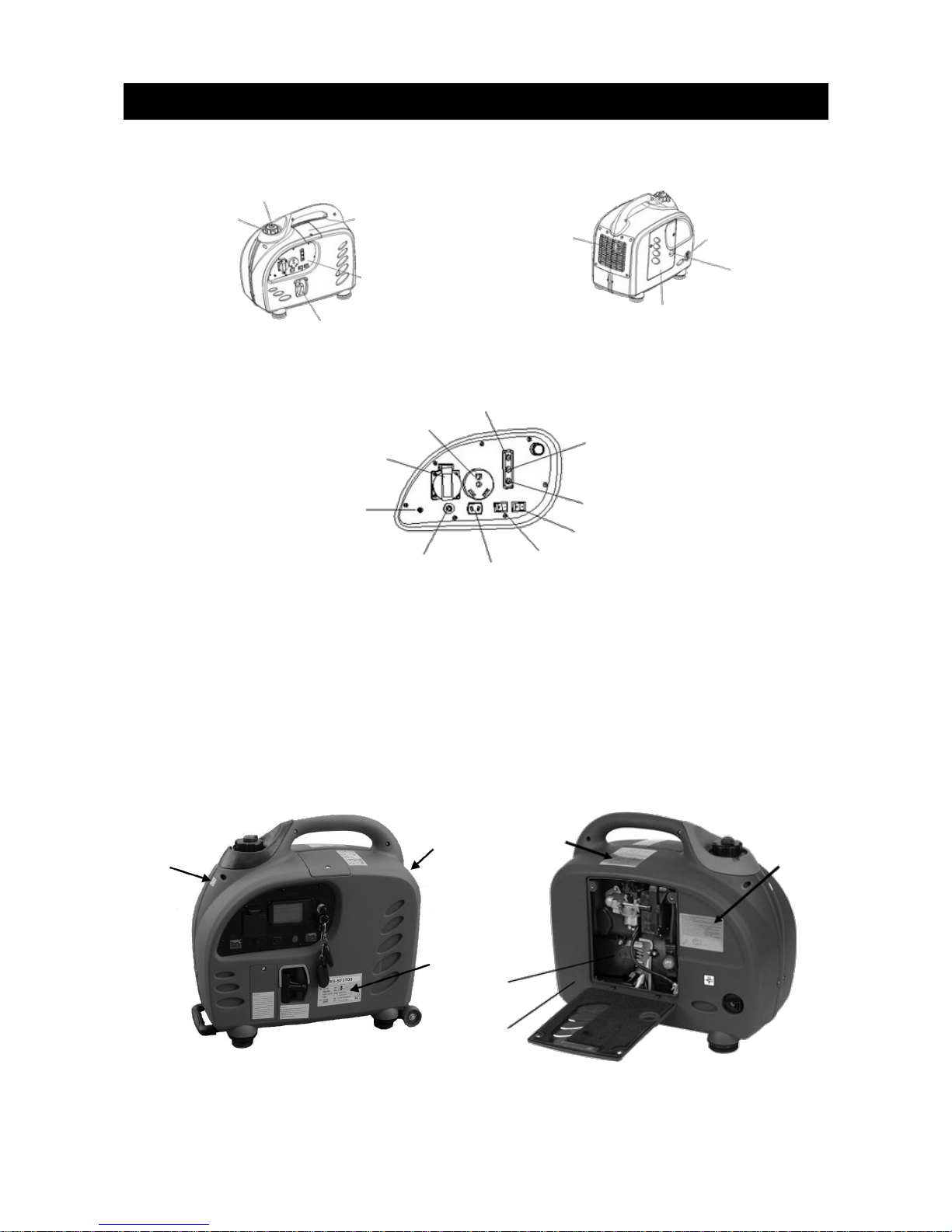
Product Layout
Unit Body
Control Panel
Smart Throttle
The engine speed is kept at idle automatically when an electrical appliance is disconnected, and
will return again to proper speed when an electrical appliance is connected. This is designed to
minimise fuel consumption during operation.
Safety Label Locations
These labels warn you of potential hazards that can cause serious in ury. Read the labels and
safety notes and precautions described in the manual carefully.
3
Air Vent Knob
Fuel
Cap
Top Maintenance
Cover
Control
Panel
Starting Grip
Muffler
Cover
Fuel Valve
Primer Bulb
Maintenance
Access
Overload Indicator
Light
Output Indicator
Light
Oil Alert Indicator Light
Eco Throttle Switch
Engine Switch
DC
Socket
DC Circuit
Breaker
Grounding
Terminal
AC Socket
AC RV
Socket
Avoid Fire
Label
Avoid Burns
Label
Parameter
Label
Ventilation
Label Primer Bulb
Label
EPA Label
EPA Label
Pre-operation Checks
•Be sure to check the generator is on a level surface with the engine stopped.
•Check the engine oil level.
•Using 2-stroke engine oil could shorten the engine's service life. Use a premium quality
4-stroke engine oil.
Checking the Oil
•Loosen the cover screw and remove the left side maintenance cover. Remove the oil filer
cap, then wipe the dipstick with a rag. Check the oil level by reinserting the dipstick into
the filler hole without screwing it in.
•If the oil level is below the end of the dipstick, refill up to the top of the oil filler neck.
ote: The Oil Alert System will automatically stop the engine before the oil level falls below the
safe limit, however to avoid the inconvenience of an unexpected shut-down, it is still advisable
to visually inspect the oil level regularly.
4
Dipstick
Lowest oil
level allowed

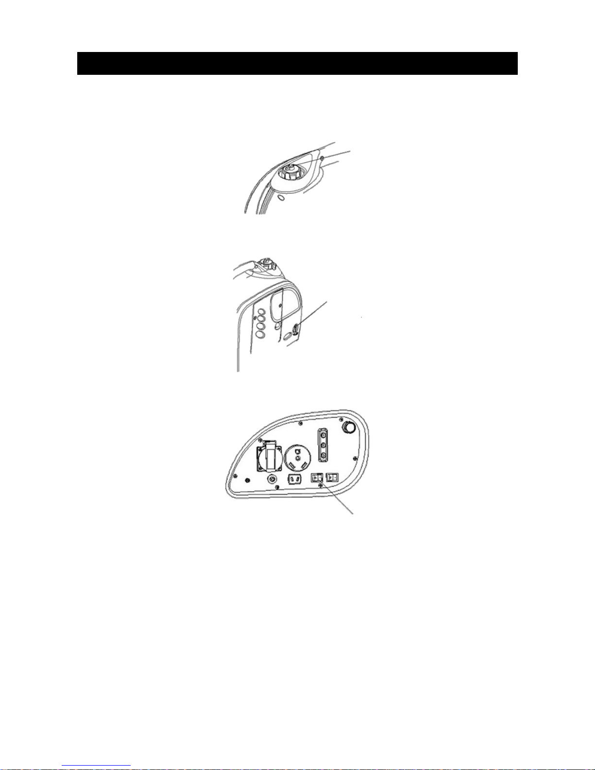
Checking the Fuel Level
•Turn the fuel cap lever to the “OFF” position before transporting.
•Use unleaded automotive fuel.
ote: DO NOT use any fuels containing alcohol. Fuel system damage or engine performance
problems resulting from the use of fuels that contain alcohol are not covered by warranty.
•Never use an oil/petrol mixture or dirty fuel.
•Avoid getting dirt, dust or water in the fuel tank.
•After refuelling, tighten the fuel filler cap securely.
•Petrol is extremely flammable under certain conditions.
•Refuel in a well-ventilated area with the engine stopped.
•Do not smoke or allow flames or sparks in the area where the engine is refuelled or where
petrol is stored.
•Do not overfill the fuel tank. After refuelling, make sure that the tank cap is closed
properly and securely.
•Be careful not to spill fuel when refilling. Spilled fuel or fuel vapours may ignite. If any fuel
is spilled, make sure the area is dry before starting the engine.
•Avoid repeated or prolonged contact with skin, or the breathing of vapour.
•KEEP FUEL OUT OF REACH OF CHILDREN
Check the Air Cleaner
Check the air cleaner element to ensure it is clean and in good working condition.
1. Loosen the cover screw and remove the left side maintenance cover.
2. Press the latch tab on top of the air cleaner body, remove the air cleaner cartridge, then
check the element.
3. Clean and replace the element if necessary.
Never run the engine without the air cleaner. Rapid engine wear will result from airborne
contaminants such as dust and dirt being drawn through the carburettor and into the engine.
It is normal for a little oil to appear under the air filter box if the generator is running for a long
period of time or if a lot of oil is in the engine. Wipe up excess oil after each use and after
stopping the generator.
5
Fuel Cap
Open
Air Cleaner
Cartridge
Air Cleaner
Case
Screws
Access Panel
Screws
Access Panel Air Cleaner
Element

LCD Display Layout
The LCD display will light up after the generator has started up, and will be functioning after 3-5
seconds.
Running display instructions
•U : Voltage
Displays the current voltage (V). The XXX.X (V) format (one decimal).
•I : Current
Displays the current Current (A). The XX.X (A) format (one decimal).
•F : Frequency
Displays the current frequency (Hz). The XX.X (Hz) format (integer).
•P : Power
Displays the current Power (W). The format is XXXX.X (W) (integer).
•Oil : Fuel
Invalid
•Time : Running Time
Displays the total running time. The format is xxx: xx: xx (hr: m: sec)
Overload / Oil Sensor light
Overload
The LCD screen will display the current output when the generator
is running normally. When the generator is overloaded or short
circuited, the generator will not supply power to appliances. The
voltage, current and frequency will display “0” and the power
display will show “OVER”.
At this time, the generator is not automatically shut down. Please
manually shut the generator down and investigate the reason of
the overload.
Oil Sensor
The oil sensor system is to prevent engine damage
due to not enough oil being in the reservoir. The oil
sensor light will light up in red before the oil level is
under the safe line in the crankcase, while the oil
system shutdown of the generator is automatic.
6
0
Over
Oil sensor
light

Attaching the wheels to the generator
1. Fix the wheel to the axle.
2. Fix the washer onto the wheel axle.
3. Fix the dowel onto the axle.
Using the remote controller & emergency button
ote: the generator can be started by using the starting key &
remote control.
•Use the starting key, not the remote controller, to stop the
generator when the generator has been started by the
starter key.
•Use the remote controller, not the starting key, to stop the
generator when the generator has been started by the
remote control.
•The emergency stop button can be used to stop the
generator at all times, no matter which method was used to
start the generator.
7
Axle
2 wheels,
2 washers,
2 dowels
Dowel
Washer
Wheels
Wheel
assembly
Fix dowel
on axle
Remote
controller
Starting
key
Emergency
stop button
Stop
Start
Press button
twice to start
generator.
Generator
remote control
Starter key
Using the Generator
Starting the Engine
1. Before starting the engine, disconnect any load from the DC receptacle. Turn the fuel cap
lever fully clockwise to the ON position.
2. Set the fuel valve to the ON position.
3. Set the motor switch to the ON position.
4. Pull slightly on the start cord until you feel resistance, then yank hard and swiftly.
•Do not let the start cord retract by itself, but instead guide it back by hand.
•Hold the carry handle firmly to prevent the generator from falling over when you pull the
start cord.
ote: A hot motor will not start if there is too much fuel in the cylinder. If this happens, wait for
five to ten minutes before trying again.
8
Fuel Cap
Lever
Turn the fuel
valve knob to
the ON position
Engine Switch

Once the engine has started, allow the engine to run continuously and warm up.
If the engine stops and will not restart, check the engine oil level before troubleshooting in other
areas.
Before using a device once it is connected, switch the ECO switch off.
High Altitude Operation
At high altitudes, the standard carburettor air/fuel mixture will be excessively rich. Performance
will decrease and fuel consumption will increase.
High altitude performance can be improved by installing a smaller diameter main fuel et in the
carburettor and read usting the slow tempo screws. If you always operate the generator at
altitudes higher than 1,500m (4,000 feet) above sea level, have a specialist perform these
carburettor modifications.
Even with suitable carburettor etting, engine horsepower will decrease by approximately 3.5%
for each 300m (1,000 feet) increase in altitude. The effect of altitude on the horsepower will be
greater than this if no carburettor modification is made.
ote: Operation of the generator at an altitude lower than the carburettor is etted for may
result in reduced performance, overheating and serious engine damage caused by excessively
lean air/fuel mixture.
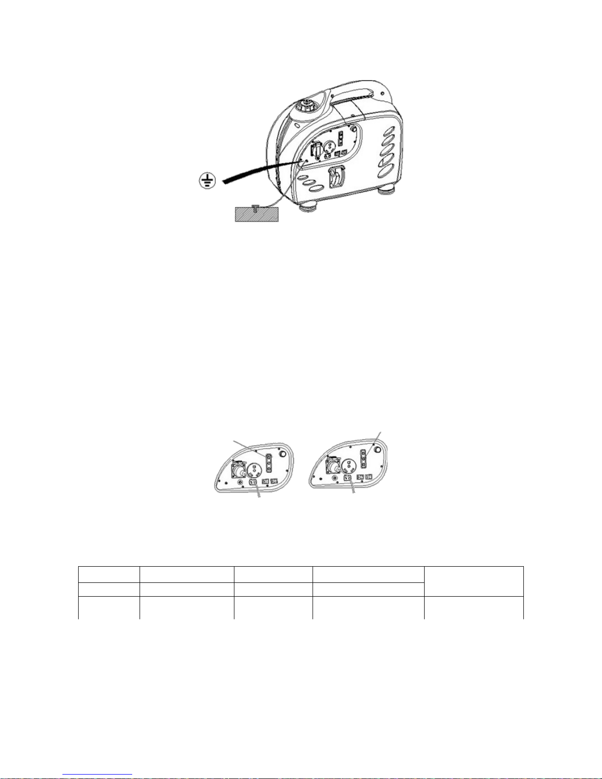
Generator Use
•To prevent electric shock from faulty appliances, the generator should be grounded.
Connect an electric conductor (cable) of at least 1.5mm2 between the generator's
ground terminal and an external ground source.
•Connections for standby power to a building's electrical system must be made by a
qualified electrician and must comply with all applicable laws and electrical codes.
Improper connections can allow electrical current from the generator to feedback into
the utility lines.
•Do not exceed the current limit set by any one receptacle.
•Do not connect the generator to a household circuit. This could cause damage to either
the generator, or to electrical appliances in the house.
•Do not modify or use the generator for any purpose other that what it is intended for.
•Keep the generator away from other electrical cables or wires such as the distribution
network.
•The DC receptacle can be used while AC power is in use. If you use both at once, ensure
you do not exceed the total power for AC and DC.
•Most appliances require more than their rated wattage for start up.
9
Starting Grip

AC Applications
Start the engine and make sure that the output indicator light (green) illuminates.
Confirm that the appliance to be used is switched off, then plug the appliance in.
Substantial overloading that continuously lights the overload indicator light (red) may damage
the generator. Marginal overloading that temporarily lights the overload indicator light may
shorten the life of the generator.
Be sure that all appliances are in good working order before connecting them to the generator.
If an appliance begins to operate abnormally, becomes sluggish or stops suddenly, turn the
generator engine switch off immediately. Then disconnect the appliance and examine it for
signs of malfunction.
Output and Overload Indicators
The output indicator light (green) will remain lit during normal operating conditions.
If the generator is overloaded, or there is a short in the connected appliance, the output
indicator light will go OFF, the overload indicator light (red) will go ON and current to the
connected appliance will be shut off.
Stop the engine if the overload indicator light goes ON and investigate the overload source.
ote: Before connecting an appliance to the generator, check that it is in good working order
and that its electrical rating does not exceed that of the generator. Then connect the power
cord of the appliance and start the engine.
ote: Before sure all equipment is turned off before connecting the power cord.
When an electric motor is started, both the overload indicator light (red) and the output
indicator light (green) may go on together. This is normal and the overload indicator light should
go out after about four seconds.
If the overload indicator light stays on, contact the Kogan customer support team.
10
Overload Indicator
Light (Red)
Output Indicator
Light (Green)
Overload
Indicator (Red) Output
Indicator (Green)
Oil Alarm Indicator
Connect the ground terminal.
Start the engine according to the “Starting the Engine” chapter of this manual.
ote: If the output indicator light (green) does not light, and the overload indicator light (red)
lights up instead, set the engine switch to STOP, stop the engine at once, then start the engine
again.
Confirm that the equipment to be used is switched off, and insert the plug of the appliance to be
used into the AC receptacle.
ote: Double check that the equipment to be used is switched off before plugging it in.
Equipment to be used will operate suddenly and in uries or accidents may be caused.
Switch the equipment on and the output indicator light should light up. In the event of overload,
the output indicator light will go out and the overload indicator light will come on. No power will
be output, however the engine will not have stopped, so the engine must be stopped by setting
the respective engine switch to STOP.
ote: When equipment requires a large starting power, the overload indicator light and the
output indicator light may light together for a short time. This is not an abnormality. Once the
equipment has started, the overload indicator light will go out and the output indicator light will
stay lit.
AC Electric Lamps Power Tools Electromotor DC Battery
Power Factor 1 0.8 ~ 0.9 0.4 ~ 0.7 (efficiency 0.86)
3700 0-2600W 0-2000W 0-10002
Rated Voltage: 12V
Rated current: 8A
11
Grounding
Mark
When overloaded
or short-circuited,
overload indicator
will illuminate (red).
Normal operations:
output indicator will
illuminate (green).

DC Applications
For charging 12V automotive batteries:
Idling voltage (V) Loading voltage (V) Loading current (A)
DC Max. Output
Power
37 13.5 8.5
The generator cannot sense a sensibility load with the same power, which the manual indicates.
It can only sense 40%-70% power.
Example:
Generator Rated Output 4.4KVA
Frequency Power Factor
AC 1.0 4.4KVA
0.4 ~ 0.75 0-1.3KVA ~ 2.4KVA
DC 100W
(12V/8.3A)
•When using the DC output, turn the smart throttle to the OFF position. The DC current
will be below 5A if you turn on the smart throttle without AC current output.
•When charging batteries, a person must always be present to monitor the voltage.
Charging must be stopped once the voltage of the batteries is above 16V, or it may cause
the battery to explode, causing serious in ury or death.
•To prevent the possibility of creating a spark near a battery, connect the charging cable
to the generator first, then to the battery. Disconnect the cable first at the cable.
•Before connecting charging cables to a battery that is installed in a vehicle, disconnect
the vehicles grounded battery cable. Reconnect the vehicles grounded battery cable
after the charging cables are removed. This procedure will prevent the possibility of a
short circuit and sparks if you make accidental contact between a battery terminal and
the vehicles frame or body.
•Do not attempt to start an automobile engine while the generator is still attached to the
battery. The generator may be damaged.
•Connect the positive battery terminal to the positive charging cord. Do not reverse the
charging cords, or you may damage the battery or generator.
•The battery gives off explosive gases; keep sparks, flames and cigarettes away. Provide
adequate ventilation when charging.
•The battery contains sulphuric acid (electrolyte). Contact with skin or eyes will cause
severe burns. Wear protective clothing and a face shield.
If electrolyte gets on your skin, flush with water.
•If electrolyte gets in your eyes, flush with water for at least 15 minutes and call 000.
•If electrolyte gets swallowed, drink large quantities of water or milk, then follow with milk
of magnesia or vegetable oil. Call 000.
•KEEP OUT OF REACH OF CHILDREN, PETS AND UNTRAINED PERSONS.
12
Charging
Wires

Starting the Engine
•The DC receptacle may be used while the AC power is in use.
•An overloaded DC circuit will trip the DC circuit protector. If this happens, disconnect the
DC load before pushing in the circuit protector to resume operations.
Oil Alert System
The oil alert system is designed to prevent engine damage caused by an
insufficient amount of oil. The alert system will automatically shut down the
engine (the engine switch will remain in the ON position).
If the oil alert system shuts down the engine, the oil alert indicator light (red)
will come on when you operate the starter, and the engine will not run. If this
occurs, add engine oil.
Stopping the Engine
To stop the engine in an emergency, turn the engine switch to the OFF position.
In normal use:
1. Switch off the connected equipment and pull the inserted plug out.
13
DC Circuit Breaker
Oil Alarm Indicator (Red)
Plug
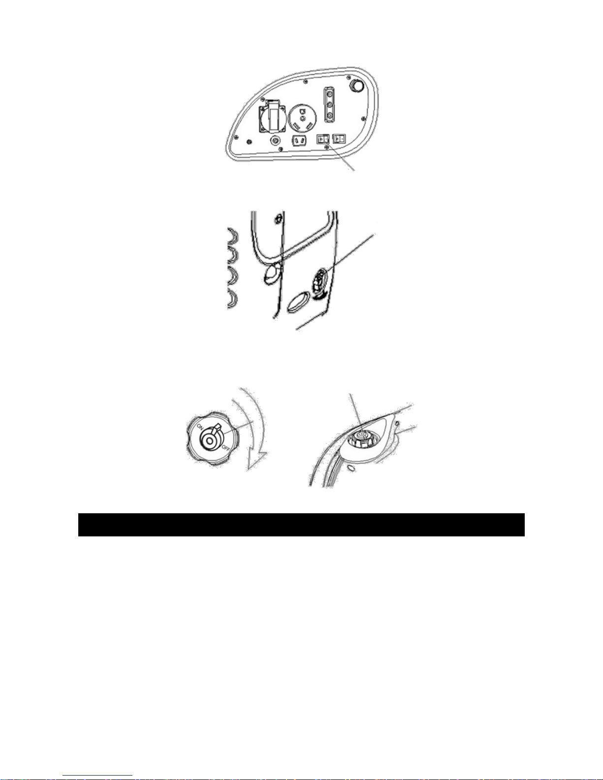
2. Turn the engine switch to the OFF position.
3. Turn the cap lever fully counter-clockwise to the OFF position.
ote: Be sure that both the fuel cap lever and the engine switch are in the OFF position before
stopping, transporting and/or storing the generator.
Maintenance
The purpose of the maintenance and ad ustment schedule is to keep the generator in the best
operating conditions.
Inspect or service as scheduled in the table below.
ote: Shut off the engine before performing any maintenance. If the engine must run during it,
make sure the area is extremely well ventilated. The exhaust does contain poisonous carbon
monoxide gas.
14
Engine Switch
Turn the fuel
valve knob to
the OFF
position.
Open
Close
Air Vent Knob

Maintenance Schedule
Regular service period (1)
___________________________
Item operation to perform
Each Use First month or
20 hours
Every 3
months or 50
hours
Every 6
months or 100
hours
Every year or
200 hours
Engine oil Check level ●
Change ● ●
Air cleaner Check ●
Clean (2)●
Spark plug Check / ad ust ●
Combustion
chamber
Clean ●
Valve clearance Check / ad ust (3)●
Fuel tank and filter
tank
Clean (3)●
Fuel line Check Every 2 years – replace if necessary (3)
1. Log hours of operation to determine proper maintenance.
2. Service more frequently when used in dusty areas.
3. These items should be serviced by a qualified technician, unless the owner has the proper tools and is
mechanically proficient.
Temperature (°C) Time between oil changes (hour) Recommended Power Factor
25 Normal 100%
30 18 95%
35 15 85%
40 12 70%
ote: if the temperature of the external environment reaches 45°C or higher, the generator
should not be used, as it may be damaged. If the external environment reaches -5°C or lower,
the generator should not be used.
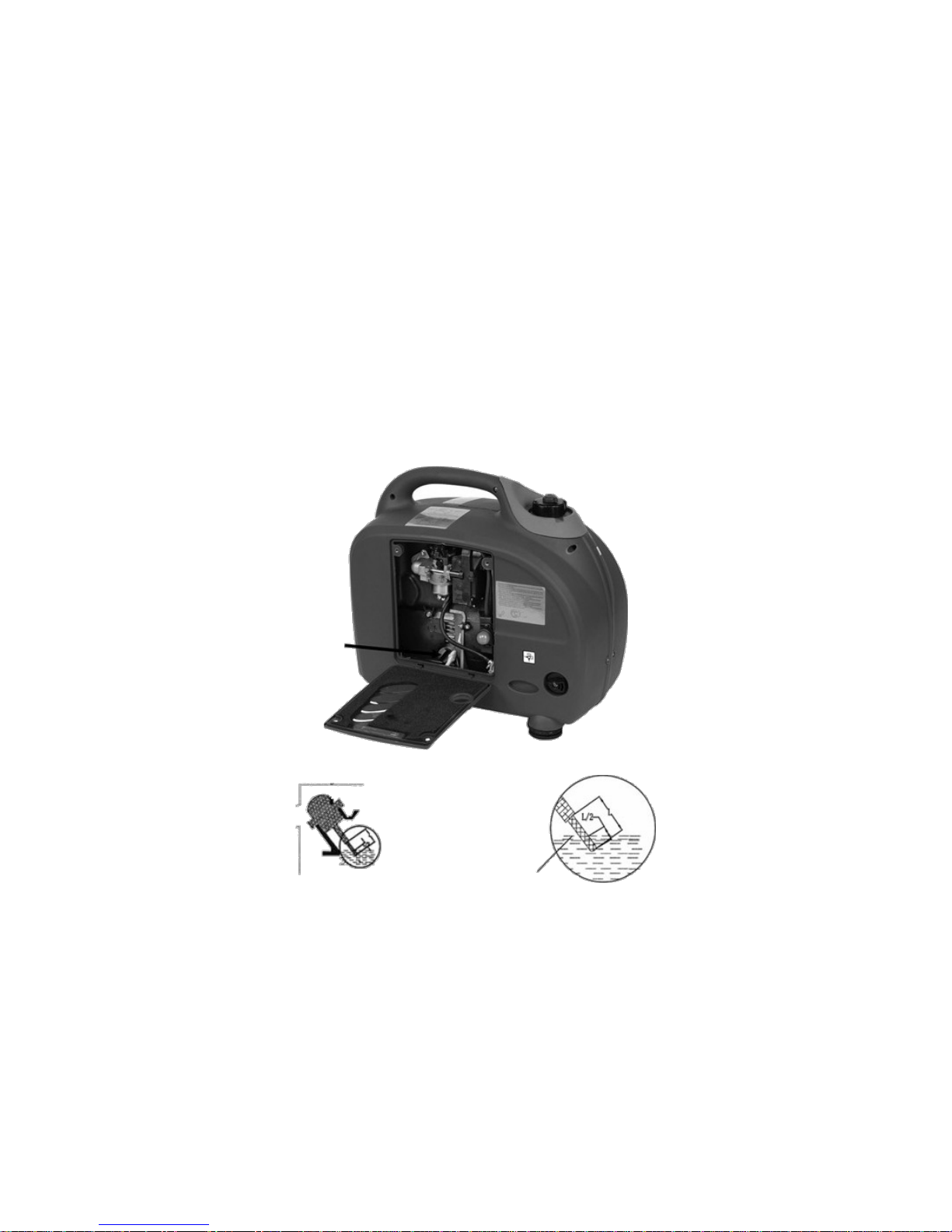
Changing Oil
Drain the oil while the engine is still warm to ensure rapid and complete draining.
ote: make sure to turn the engine switch and the fuel cap vent lever OFF before draining the
oil.
1. Lean the generator to the side.
2. Fasten the oil lead pipe onto the oil exhaust as shown in the picture overleaf. Then pour
out the oil.
3. Refill with new oil and check the oil position in the crankcase.
4. Once the crankcase has new oil in it, please gently shake the generator from left to right
a few times to ensure that the bobber used for the oil alarm system is floating.
Engine oil capacity: 0.9L
15

Wash your hands with soap and water after handling used oil.
ote: Please dispose of used motor oil in a manner that is compatible with the environment. We
suggest that you transport it in a sealed container to your local service station or municipal
waste disposal facility for reclamation.
DO OT dispose of it in the trash, pour it on the ground or pour down a sink or into a
stormwater drain.
16
Generator
Oil Drain
Pipe
Oil Container
Dipstick
Lowest oil
Level allowed
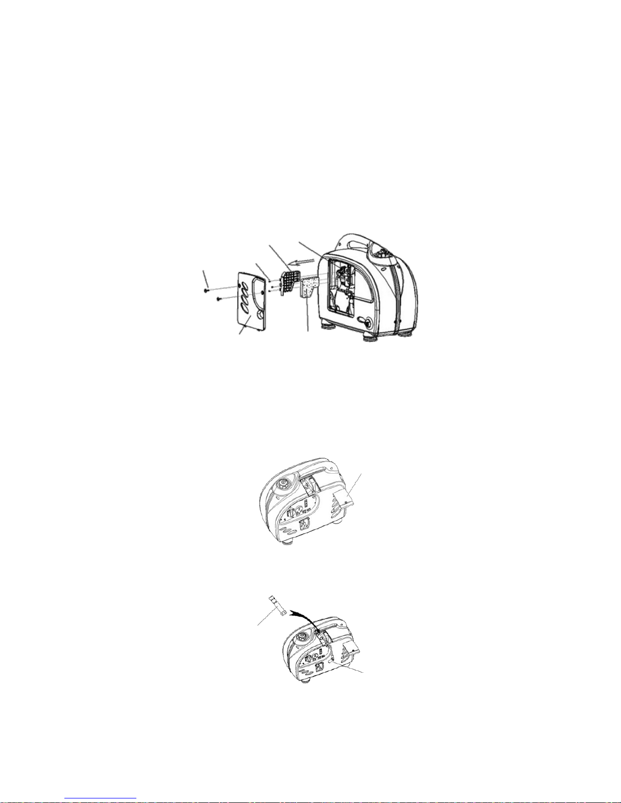
Air Cleaner service
A dirty air cleaner/filter will restrict airflow to the carburettor To prevent carburettor
malfunctions, service the air cleaner/filter regularly. Service more frequently when operating the
generator in extremely dirty areas.
ote: do not use gasoline or low flash point solvents for cleaning. They are highly flammable and
explosive under certain conditions.
1. Loosen the cover screw and remove the access panel.
2. Remove the screw under the air filter case.
3. Pull the air filter cartridge down 30mm and remove the air filter cartridge.
4. Remove the air filter iron clip and check the air filter element. Clean or replace the
element if necessary.
5. Reinstall the air filter parts after cleaning or replacing the air filter element.
Spark Plug Servicing
Please use high quality spark plugs for best performance.
To ensure proper engine operation, the spark plug must be properly gapped and free of
deposits.
1. Remove the bolts on top of the maintenance cover and the cover.
2. Take out the ignition coil rubber boot.
17
Air cleaner case
Air cleaner
cartridge
Screws
Access panel
screws
Access panel Air cleaner
element
Top maintenance cover
Spark plug wrench
Ignition coil rubber boot

3. Remove the spark plug with the spark plug wrench.
4. Visually inspect the spark plug. Discard if the insulator is cracked or chipped. Clean the
spark plug with a wire brush if it is to be reused.
5. Install the spark plug carefully by hand to avoid cross threading.
6. After a new spark plug has been seated by hand, it should be tightened turn with a ½
wrench to compress its washer. If a used plug is being reinstalled, it should only require a
1/8 to turn after being seated.¼
7. Reinstall the ignition coil rubber boot on the spark plug securely.
8. Reinstall the control panel.
ote: the spark plug must be securely tightened. An improperly tightened plug can become
extremely hot and may damage the generator. Never use a spark plug with an improper heat
range.
Never use a spark plug without damping resistance, or it will cause no AC output.
Transporting and Storage
To prevent spillage when transporting or during temporary storage, the generator should be
secured upright in its normal operating position, with the engine switch OFF.
The fuel cap vent lever must be turned counter-clockwise to the OFF position.
Allow the engine to cool completely before turning the fuel cap vent lever to the OFF position.
18
Spark plug
wrench
Screwdriver
Insert the screwdriver into the hole of the spark plug wrench and remove the spark
plug.
0.6 ~ 0.7mm
(0.024 ~ 0.028”)

Transporting the generator
•Do not overfill the tank. (There should be NO fuel in the filler neck.)
•Do not operate the generator while it is in a vehicle. Take the generator out of the vehicle
and operate it in a well ventilated area.
•Avoid a location exposed to direct sunlight when putting the generator in a vehicle. If the
generator is left in an exposed vehicle for many hours, the high temperatures inside the
vehicle may cause fuel to vapourise, resulting in a possible explosion.
•Do not drive on a rough road for an extended period of time with the generator on
board. If you must travel with the generator on board over rough roads, drain all of the
fuel from the generator beforehand.
Before storing the unit for an extended period
1. Be sure the storage area is free of excessive humidity and dust.
2. Drain the fuel.
ote: fuel is extremely flammable and explosive under certain conditions. Do not smoke
or allow flames or sparks in the area.
3. Completely drain the fuel from the tank. Open the fuel valve, start the engine and operate
in the idle position until all remaining fuel is gone and the engine stops automatically.
4. Discharge the oil.
5. Remove the spark plug and fill the cylinder with 2cc's of fresh oil. Pull the start motor 3-4
times to discharge the remaining oil, then reinstall the spark plug.
6. Pull the starting cord slowly until the resistance is strong. At this time, the piston is
moving to the top of the compression stroke and the valves will be closed.
Muffler Fire et Service
A dirty muffler will result in high operating noise, and will also affect the engine's running quality.
Clean and maintain the fire net in the muffler, to ensure that the machine is cooling efficiently.
1. Remove the M6 screws and open the muffler cover.
2. Remove two M4 screws on the fire net.
3. Take down the fire net as per the following image.
4. Check the fire net. Clean or replace it as necessary.
19
Fuel
Container
Other manuals for CTINV35GENA
1
Table of contents
Other Certa Inverter manuals


