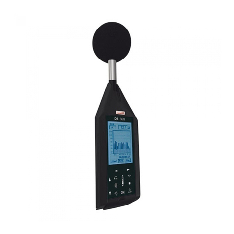
Kimo DB 200 User manual

Sound level meter
DB 200

Table des matières
1 Introduction...........................................................................................................................................4
2 Vocabulary............................................................................................................................................5
3 Presentation of the sound level meter.................................................................................................6
3.1 Overview.......................................................................................................................................6
3.2 Presentation of the screen keyboard group.................................................................................7
4 Settings.................................................................................................................................................8
4.1 Configuration.................................................................................................................................8
4.2 I/O.................................................................................................................................................8
4.3 Contrast backlight.......................................................................................................................9
4.4 Autonomy......................................................................................................................................9
4.5 Instrument.....................................................................................................................................9
4.6 About.............................................................................................................................................9
5 Make some measurements................................................................................................................10
5.1 Conventional sound level meter function....................................................................................10
5.1.1 Adjustment prior to measurement.......................................................................................10
5.1.2 Launch the measurement....................................................................................................10
5.1.3 During measurement...........................................................................................................10
5.2 Conventional sound level meter with storage function...............................................................11
5.2.1 Adjustment prior to measurement........................................................................................11
5.2.2 Launch the measurement....................................................................................................11
5.2.3 During measurement...........................................................................................................11
5.2.4 Stop the measurement........................................................................................................12
5.2.5 Store data............................................................................................................................12
5.3 Classical sound level meter and averager integrator function...................................................13
5.3.1 Adjustment prior to measurement.......................................................................................13
5.3.2 Launch the measurement....................................................................................................13
5.3.3 During measurement...........................................................................................................13
5.3.4 Stop the measurement........................................................................................................14
5.3.5 Store data............................................................................................................................14
5.4 Sound level meter and averager integrator with storage function..............................................15
5.4.1 Adjustment prior to measurement.......................................................................................15
5.4.2 Launch the measurement....................................................................................................15
5.4.3 During measurement...........................................................................................................15
5.4.4 Stop the measurement........................................................................................................16
5.4.5 Store data............................................................................................................................16
5.5 Calculate two sound sources......................................................................................................17
5.5.1 Adjustment prior to measurement.......................................................................................17
5.5.2 Make calculation of two sound sources...............................................................................17
5.5.3 Store data............................................................................................................................18
5.6 Determine a sound source among two.......................................................................................18
5.6.1 Adjustment prior to measurement.......................................................................................19
5.6.2 Make the measurement.......................................................................................................19
5.6.3 Store data............................................................................................................................19
5.7 Sound level meter in I/O mode...................................................................................................20
5.7.1 Launch a measurement in I/O mode...................................................................................20
6 Read the stored files..........................................................................................................................21
6.1 Access to files.............................................................................................................................21
6.2 Read all data file.........................................................................................................................21
6.2.1 L St mode file.......................................................................................................................21
6.2.2 L Leq mode file....................................................................................................................22
6.2.3 Leq St mode file...................................................................................................................22
6.2.4 S1+S2 mode file..................................................................................................................23
7 Transfer files to a PC..........................................................................................................................24
8 Reset memory....................................................................................................................................25

9 Directions for use and sound level meter maintenance.....................................................................26
9.1 Use warnings..............................................................................................................................26
9.2 Directions for use........................................................................................................................26
9.3 Calibration...................................................................................................................................26
9.4 Maintenance...............................................................................................................................27
9.5 Regular checking........................................................................................................................27
9.6 Change batteries.........................................................................................................................27
9.7 Replace the batteries with a battery pack...................................................................................27
9.8 Load the battery..........................................................................................................................28
9.9 AC adapter..................................................................................................................................28
10 Running informations.......................................................................................................................29
10.1 Over range................................................................................................................................29
10.2 Power........................................................................................................................................29
11 Technical features.............................................................................................................................30
11.1 Microphone................................................................................................................................30
11.1.1 Sheet..................................................................................................................................30
11.1.2 Frequency response type – reference direction of the sound level meter........................30
11.2 Windscreen...............................................................................................................................30
11.3 Measured and displayed values...............................................................................................31
11.4 A – C – Z weightings and free field response...........................................................................31
11.5 Metrology...................................................................................................................................32
11.5.1 Main features.....................................................................................................................32
11.6 Plugs and connections..............................................................................................................32
11.6.1 I/O Interface.......................................................................................................................33
11.6.2 Transfer plug / load / mains voltage adaptor.....................................................................33
11.7 Memory and storage autonomy................................................................................................33
11.8 Power and storage autonomy...................................................................................................34
12 Packaging and accessories.............................................................................................................35
12.1 Supplied with.............................................................................................................................35
12.2 Optional.....................................................................................................................................35
13 LDB200 software..............................................................................................................................36

1 Introduction
The DB200 sound level meter is an acoustic measurement instrument with main features of a conventional and integrating-averaging
sound level meter.
With its memory, DB200 sound level meter stores measurement datasets. Then they are transferred to a computer and processed
through LDB200 software.
According to international standards, sound level meter calculates and displays on its graphical backlight LC -screen values used for a
fast and complete study of the noise environment.
To simplify and make nice its use, 5 measurement modes have been preselected :
•Mode 1 : Conventional sound level meter (See p.10)
•Mode 2 : Conventional sound level meter with storage (See p. 11)
•Mode 3 : Conventional and integrating-averaging sound level meter (See p. 13)
•Mode 4 : Integrating-averaging sound level meter with storage (See p. 15)
•Mode 5 : Sound level meter « calculator » of two sound sources (See p 17)
In the different modes, in addition to measured values, the sound level meter can display :
•results for a better definition of the acoustic environment :
Maximum and minimum values, peak values, statistics distribution of measured levels
•Indications required for the proper validation of the measurement :
Presence and percentage of overload input stages, duration of the measurement
•other information :
attery autonomy, remaining measuring capacity
The sound level meter also communicates with an automaton through I / O plugs :
•0-10 V C analog output
•Control bit activated as per pre-programmed threshold
•Launching and stop of measurement by the automaton
Introduction 4

2 Vocabulary
The terms and abbreviations listed below will be used throughout this user manual.
L : represents the measurement mode: conventional sound level meter
L-St : represents the measurement mode : conventional sound level meter with storage function. The sound pressure level is stored into the
memory at a sampling rate which is defined and planned.
L-Leq : represents the measurement mode : conventional and integrating-averaging. Values are measured simultaneously.
L-St : represents the measurement mode : integrating-averaging sound level meter with storage function The equivalent continuous sound level on
the logging time ( I) is stored into the memory.
S1+S2 : denomination for measuring or calculating the levels of 2 sound sources.
LXeq : X-weighted equivalent continuous sound level on the logging time or on the total time of the measurement.
LXeqM : Maximum X-weighted equivalent continuous sound level on the logging time, on the total time of the measurement.
LXeqm : Minimum X-weighted equivalent continuous sound level on the logging time, on the total time of the measurement.
LXE : X-weighted sound exposure level.
LXY : X-weighted acoustic pressure level ; time weighting : Y
LXYmax : Maximum X-weighted sound pressure level ; time weighting : Y
LXYmin : Minimum X-weighted sound pressure level ; time weighting : Y
LUpK : U-weighted peak sound level.
Echant. : time between two successive storages of the sound pressure level into the memory, also called : Sampling rate.
DI : Programmable logging time for the calculation of the equivalent continuous sound level stored into the memory, also called : elementary
integration time.
X : generic marking for frequency weightings, A – C or Z standardized (L, Leq, LE values)
U : generic marking for frequency weightings, C or Z standardized (Lpk values)
Y : generic marking for time weightings with : « F » for Fast, « S » for Slow or « I » for Impulse.
Man : manual mode of measurement launching
I/O : Launching mode of the measurement controlled by I/O plugs.
SXX : order number of the measurement sessions. Limited to 25.
RST : reset of calculations of maximum or minimum values memorized – erasing of measurement session or of the whole memory.
Sto. : storage of measurement session into the memory.
S1 : name for measuring or calculating the equivalent continuous sound level of a first sound source.
S2 : name for measuring or calculating the equivalent continuous sound level of a second sound source.
S1+S2 : name for measuring or calculating the equivalent continuous sound level of the two sound sources.
00/00:00:00 : format of the measurement time in ays/hours:minutes:seconds
00/00:00 : format of the measurement time in ays/hours:minutes
00:00:00 : format of the measurement time in ays/hours:minutes:seconds or format of the current time
18/11 : format of date
00:00 : format of current time in hours/minutes
Pond. : A, C or Z frequency weightings
Cte : time weighting or time constant : Fast – Slow - Impulse
S/S : integration time controlled in Manuel mode : Start/Stop
C.Cl : free field correction term in calibration mode.
Corr. : corrective term of nominal benefit in calibration mode.
L01 – L10 – L50 – L90 – L95 : Normalised statistics distribution, used in environmental studies
5 Vocabulary

3 Presentation of the sound level meter
3.1 Overview
The back of the instrument contains a battery compartment door, a threaded hole for mounting on a tripod, a location for the nameplate
and a location for the calibration label.
Presentation of the sound level meter 6
Preamplifier
Graphical backlighted LCD-
screen : 240 x 160 pixels.
It displays both reserved areas
for the setting of the
measurement and areas for
results presentation.
Monochrome, with 16 grey/blue
levels, it participates to the
intuitive manipulation of the
sound level meter .
ottom part : protected by a flexible and removable
rubber breastplate, it contains all input/output and
external power plugs.
Windscreen : essential to
reduce the noise induced by air
currents.
Keyboard : it consists of only 8
sensitive keys. Its ergonomy allows
an immediate and easy use of the
sound level meter.
Electret microphone
Severable from the preamplifier
(inside the windscreen).

3.2 Presentation of the screen-keyboard group
The screen/keyboard group gives to the instrument a modern ergonomy. It mainly participates to the quick
familiarization of the sound level meter.
A press, a touch or a very light finger slipped on keyboard icon is enough to trigger the corresponding action of
the sensitive key.
The measurement configuration is made by moving a reversed video cursor in reserved areas, then by
choosing the concerned parameter or function.
For instance :
•Time weighting choice : Slow, fast or Impulse.
•Frequency weighting choice : A, C or Z.
•Measurement mode choice : L, L-St, L-Leq or Leq-St.
Reserved areas appear according to two 3 type formats :
•Inner shadow to the frame : simulates a shifted back area in which parameters can be modified or displayed
measurement results.
•External shadow to the frame : simulates a shifted forward area in which different propositions of the menu
can be chosen to go to an other configuration or validation screen.
7 Presentation of the sound level meter
A push on each arrow moves the cursor on the horizontal left-right axis.
A push on each arrow moves the cursor on the vertical up-down axis.
scrolling knob key : increases or decreases suggestions in the area according the principle of front or back circular
permutation. The finger must slide from an arrow to the other one, simulating a scroll wheel action.
From the bottom to the top to increase or from the bottom to the top to back to the previous proposal.
Validate a suggestion or an action to lead present in an outer shaded frame.
Go to the main menu to return to the previous screen.
Exit a menu screen to return to the previous screen.
Launch a measurement, then pause it if necessary .
Finally stop measurement
Enable-disable the backlight.
On-Off

4 Settings
From the key a screen lists the different settings or informations about the instrument.
To have access to one of those screens, scroll with the scrolling knob key and validate with OK key.
To quit each screen and back to main menu, use key.
.1 Configuration
This screen allows configuration for some functions. To have access to those functions :
Press key then choose CONFIGURATION with the scrolling knob key and OK key to validate.
From this screen, use arrow keys to move the cursor in the desired area and modify with the scrolling knob key the proposition. Various
parameters to adjust are :
•Run : systematic measurement mode when starting the device : L, L-St, L-Leq, Leq-St or S1+S2.
•Lang. : user language : French or English.
•Bip : the presence or absence of tone when pressing on the keyboard. The beep disappears by itself if it interferes with the
measurement.
•ate / Hour : Set date and time
To return to main screen, press .
.2 I/O
The I/O input/output allows to connect 2.5 mm jacks. It is located at the bottom of the unit behind the rubber breastplate.
I/O 1 corresponds to input for the launch and stop measurement from an industrial controller and is for measurement modes L-St, L-
Leq and Leq-St. Launching of the measurement is made for a continuous high level and stopping the measurement is made for a
continuous low level.
I / O 1 also corresponds to the detection output compared to a preset sound level and is for all modes of measurement. A high level
appears in output when the value of the acoustic pressure level reaches and exceeds a certain value.
For this type of output following items must be configured :
•The level type: choose L, Leq or LPK depending on the mode of measurement.
Settings 8
Menu
Menu Configuration

•Programming with scrolling knob key the desired level of detection by 1 dB steps.
•Set a timer for maintaining the continuous signal detection after sub-overshoot sound level (from 1s to 10s by 1s pitch).
I/O 2 : C continuous analogue output : 0-10V for connection to a recorder or industrial controller.
.3 Contrast - backlight
To optimize reading of the display:
➢Position the cursor on Cont. and adjust the contrast by choosing with scrolling knob key a level
of 1 to 7.
➢Position the cursor on Retro. and adjust backlight by choosing with scrolling knob key a level of
1 to 3.
. Autonomy
Autonomy provides information on the remaining memory capacity and allows time measurement according to the
chosen method of measurement and acquisition speed measurement (logging time or sampling rate).
➢Select measurement mode among L-St or Leq-St.
➢Specify the sampling rate or logging time according to the method of measurement used.
The measurement time is calculated automatically based on the remaining memory capacity. It is immediately compared to the
remaining capacity of the power system : batteries, battery or AC adapter.
A warning appears in case of incompatibility between measurement time and power capacity.
.5 Instrument
This screen reminds main components of the sound level meter :
•microphone and its serial number
•sound level meter housing
•version number of the firmware.
.6 About
This screen shows the various European standards and the accuracy class of the instrument.
It also specifies the date of the last checking and recalled next.
9 Settings
Menu I/O features
Contrast
Backlight
Instrument
Menu Autonomy Autonomy
About

5 Make some measurements
5.1 Conventional sound level meter function
The sound level meter processes the signal and displays sound pressure and at the same time following informations :
•Temporally weighted sound pressure level.
•Maximum and minimum values of levels on the measurement time.
•Level of maximum peak sound level on the measurement time.
5.1.1 Adjustment prior to measurement
1 – Select L mode : move the cursor with arrow keys to 1 and select 'L' with the scrolling knob key.
2 – Select the weighting frequency and the time weighting.
For each weighting frequency, the sound level meter proposes the measurement according to three time
weightings : Fast (F) – Slow (S) – Impulse (I). Possible choices are :
A frequency weighting : LAF – LAS – LAI
C frequency weighting : LCF – LCS – LCI
Z frequency weighting : LZF – LZS – LZI
Place the cursor with arrow key on the area 2 and select with scrolling knob identified measurement
criteria among the possibilities listed above.
3 – Select the weighting frequency of peak level of sound pressure : move the cursor with the arrows
to 3 and select C or Z with the scrolling knob key.
5.1.2 Launch the measurement
The measurement is immediate, yet it is interrupted and reset with each change.
5.1.3 During measurement
uring the measurement, two actions are possible :
•Reset memorized levels.
•Fix the measurement thanks to Pause function.
To reset all the values :
➢Press OK icon, RAZ function is activated and concerns :
•LAF maximum and minimum levels
•Value of the maximum peak pressure
•Informations about overload
Pause function allows to stop the current measurement to avoid an unwanted event or to make a manual
record of results.
Press icon to stop the measurement then press it again to resume measuring.
Note : When the sound level meter is paused, no action is specified in the "Peak" at the top of the
screen.
Make some measurements 10
1
2
3
Procedure
RAZ activation
Pause

5.2 Conventional sound level meter with storage function
The sound level meter processes the sound pressure signal and stores with a sampling rate results in a saved memory.
Data measured and stored at a sampling rate :
•Temporally weighted sound pressure level
•Maximum and minimum levels on the measurement time.
•Level of maximum peak sound pressure on the measurement time.
Sampling rate :
Stored data is made at a rate to choose from:
1s, 2s, 3s, 5s, 10s, 15s, 30s, 60s.
5.2.1 Adjustment prior to measurement
1 – Select L-St mode : move the cursor with arrow keys to 1 and select 'L-St' with the scrolling knob key.
2 – Select the weighting frequency and the time weighting.
For each weighting frequency, the sound level meter proposes the measurement according to three time
weightings : Fast (F) – Slow (S) – Impulse (I). Possible choices are :
A frequency weighting : LAF – LAS – LAI
C frequency weighting : : LCF – LCS – LCI
Z frequency weighting : : LZF – LZS – LZI
Place the cursor with arrow key on the area 2 and select with scrolling knob identified measurement
criteria among the possibilities listed above.
3 – Select the weighting frequency of peak level of sound pressure : move the cursor with the arrows to 3 and select C or Z with the
scrolling knob key.
4 – Select sampling rate : move the cursor to 4 and select with scrolling knob key among 1s, 2s, 3s, 5s, 10s,15s, 30s, 60s.
5.2.2 Launch the measurement
In manual mode : directly press icon
In I/O mode : see chapter « Launching a measurement in I/O mode »
5.2.3 During measurement
uring measurement, three screens inform the current measurement. They are accessible through the
scrolling knob key.
E1 : it is the main screen that displays the instantaneous measurements.
E2 : This screen contains results of values that will be stored in memory at the end of measurement:
•LUpk : maximum peak level of sound pressure.
•LXYmax : maximum value of sound pressure level weighted temporally met since the beginning of
the measurement.
•LXYmin : minimum value of sound pressure level weighted temporally met since the beginning of
the measurement.
•D : measurement time in /HH:MM:SS
•% : percentage of saturation of the input stage.
•Statistics indices : L01 – L10 – L50 – L90 – L95. They are calculated from stored samples.
11 Make some measurements
Procedure
1
2
3
4
Screen 2
Screen 1

E3 : this screen reminds the general format of the session of measurement:
•Start : date of measurement start
•End : date of measurement end (here, not entered because measurement is still ongoing).
•Time : measurement time (here, not entered because measurement is still ongoing).
•Mode : measurement mode type (here, L-Stock)
•Weig. : weighting frequency type (here, A)
•Cst : time weighting (here, F)
•Lpk : weighting frequency type of the peak sound level (here, C)
•Samp. : sampling rate (here, 01s)
5.2.4 Stop the measurement
We stopped the measurement manually through the pictogram.
Note : The manual command (Start - Stop) has priority over the I/O command (even if the initial choice is a start from the I/O
command).
The pause function is inoperative.
5.2.5 Store data
At the end of the measurement, in manual mode, a screen of all results is displayed. It is then possible to :
➢Accept measurements and store them : move the cursor on Sto. and press once on OK key to confirm. A banner displays the
storage phase.
➢Reject measurements and not store them : move the cursor on RST and press twice on OK key to confirm. A banner displays
the phase of suppression of data.
Make some measurements 12
Screen 3
Ongoing
measurement Results Storage
Results
Deletion
Ongoing
measurement
RST active

5.3 Classical sound level meter and averager integrator function
The sound level meter processes the signal sound pressure and simultaneously provides the following information :
•LXY : the sound pressure level weighted temporally.
•LXYmax and LXYmin : maximum and minimum values of the levels on measurement time.
•Lupk : level of maximum peak of sound pressure on the measurement time.
•LXeq : equivalent continuous level of acoustic pressure frequency weighted on measurement time.
5.3.1 Adjustment prior to measurement
1 – Select L-Leq mode : move the cursor with arrow keys to 1 and select 'L-Leq' with the scrolling knob key.
2 – Select the weighting frequency and the time weighting.
For each weighting frequency, the sound level meter proposes the measurement according to three time
weightings : Fast (F) – Slow (S) – Impulse (I). Possible choices are :
A frequency weighting : LAF – LAS – LAI
C frequency weighting : LCF – LCS – LCI
Z frequency weighting : LZF – LZS – LZI
Place the cursor with arrow key on the area 2 and select with scrolling knob identified measurement
criteria among the possibilities listed above.
3 – Select the weighting frequency of peak level of sound pressure : move the cursor with the arrows to 3
and select C or Z with the scrolling knob key.
5.3.2 Launch the measurement
In manual mode : directly press icon ,the timer starts and shows the measurement time. This time is
limited to 24 hours.
In I/O mode : see chapter « Launching a measurement in I/O mode ».
5.3.3 During measurement
uring measurement, three screens inform the current measurement. They are accessible through the
scrolling knob key.
E1 : it is the main screen that displays the instantaneous measurements.
•LXY : the sound pressure level weighted temporally.
•LXeq : equivalent continuous level of sound pressure frequency weighted on measurement time.
•LUpk : level of maximum peak of sound pressure on the measurement time.
•Duration of the measurement expressed in / HH: MM: SS
E2 : This screen contains results of values that will be stored in memory at the end of measurement :
•LUpk : level of maximum peak of sound pressure on the measurement time.
•LXYmax : maximum value of sound pressure level weighted temporally met since the beginning of
the measurement.
•LXYmin : minimum value of sound pressure level weighted temporally met since the beginning of
the measurement.
•LXeq : equivalent continuous level of acoustic pressure frequency weighted on measurement time.
•LXE : level of exposure to sound frequency weighted
•D : Measurement time expressed in / HH: MM: SS
•% : percentage of saturation of the input stage.
13 Make some measurements
Procedure
1
2
3
Screen 1
Screen 2

E3 : this screen reminds the general format of the session of measurement:
•ate of measurement start
•ate of measurement end : not entered because measurement is still ongoing.
•Measurement time : not entered because measurement is still ongoing.
•Measurement mode : L-Leq
•Frequency weighting for L and Leq : Weig.
•Time weighting for L : Cst
•Integration time for Leq : S/S (Start/ Stop mode)
•Frequency weighting of the level of pressure peak for L : Lpk
5.3.4 Stop the measurement
We stopped the measurement manually through the pictogram.
Note : The manual command (Start - Stop) has priority over the I/O command (even if the initial choice is a start from the I/O
command).
The pause function is inoperative.
5.3.5 Store data
At the end of the measurement, in manual mode, a screen of all results is displayed. It is then possible to :
➢Accept measurements and store them : move the cursor on Sto. and press once on OK key to confirm. A banner displays the
storage phase.
➢Reject measurements and not store them : move the cursor on RST and press twice on OK key to confirm. A banner displays
the phase of suppression of data.
Make some measurements 14
Screen 3
Ongoing
measurement Results Storage
Ongoing
measurement
Results RST active
Deletion

5. Sound level meter and averager integrator with storage function
The sound level meter processes the acoustic signal for each elementary integration time and stores results in a saved memory.
Measured and stored data for each integration time:
•LXeq, I : equivalent continuous sound level of acoustic pressure on the logging time and frequency weighted.
•LUpk : level of maximum peak of sound pressure on the elementary integration time.
•Measurement time expressed in /HH:MM:SS
Integration time :
ata storage is made according to logging time ( I) to choose from : 1s, 2s, 3s, 5s, 10s, 15s, 30s, 60s.
Note : In order to have permanent control of the sound pressure level before the launch of measurement, the sound level meter
calculates and displays the equivalent continuous level of acoustic pressure on a logging time of 0.5s.
5.4.1 Adjustment prior to measurement
1 – Select Leq-St mode : move the cursor with arrow keys to 1 and select 'Leq-St' with the scrolling knob key.
2 – Select the weighting frequency.
Possible choices are : A frequency weighting - C frequency weighting - Z frequency weighting.
Place the cursor with arrow key on the area 2 and select with scrolling knob A, C or Z.
3 – Select the weighting frequency of peak level of sound pressure : move the cursor with the arrows to 3
and select C or Z with the scrolling knob key.
4 – Select the I logging time :
Place the cursor on 4 and select with the scrolling knob among :
1s, 2s, 3s, 5s, 10s, 15s, 30s, 60s.
5.4.2 Launch the measurement
In manual mode : directly press icon ,the timer starts and shows the measurement time
In I/O mode : see chapter « Launching a measurement in I/O mode ».
5.4.3 During measurement
uring measurement, three screens inform the current measurement. They are accessible through the
scrolling knob key.
E1 : it is the main screen that displays the instantaneous measurements.
•LXeq0,5 : equivalent continuous level of acoustic pressure over a systematic integration time of
0,5s.
•LXeqDI : equivalent continuous level of acoustic pressure over the scheduled elementary
integration time
•LXeq : equivalent continuous level of acoustic pressure on ongoing measurement time.
•LUpk : level of maximum peak of sound pressure on the measurement time.
•Measurement time expressed in /HH:MM:SS
15 Make some measurements
Procedure
1
2
3
4
Screen 1

E2 : This screen contains results of values that will be stored in memory at the end of measurement :
•LUpk : level of maximum peak of sound pressure on the measurement time.
•LXeqM : maximum value of equivalent continuous sound pressure level of all elementary
integration times.
•LXeqm : minimum value of equivalent continuous sound pressure level of all elementary
integration times.
•LXeq : equivalent continuous level of sound pressure on the overall measurement time.
•LXE : level of exposure to sound frequency weighted.
•D : measurement time in /HH:MM:SS
•% : percentage of saturation of the input stage.
•Statistics indices : L01 – L10 – L50 – L90 – L95. They are calculated from stored samples.
E3 : this screen reminds the general format of the session of measurement:
•ate of measurement start
•ate of measurement end : not entered because measurement is still ongoing.
•Measurement time : not entered because measurement is still ongoing.
•Measurement mode : Leq-St
•Frequency weighting for Leq : Weig.
•Elementary integration time for Leq : I
•Frequency weighting of the level of pressure peak for L : Lpk
5.4.4 Stop the measurement
We stopped the measurement manually through the pictogram.
Note : The manual command (Start - Stop) has priority over the I/O command (even if the initial choice is a start from the I/O
command).
The pause function is inoperative.
5.4.5 Store data
At the end of the measurement, in manual mode, a screen of all results is displayed. It is then possible to :
➢Accept measurements and store them : move the cursor on Sto. and press once on OK key to confirm. A banner displays the
storage phase.
➢Reject measurements and not store them : move the cursor on RST and press twice on OK key to confirm. A banner displays
Make some measurements 16
Screen 2
Screen 3
Ongoing
measurement Results Storage

the phase of data deletion.
5.5 Calculate two sound sources
The sound level meter processes the acoustic signal of several sound sources over a time left to the free initiative of the operator. The
measured value here is the equivalent continuous level over this time.
5.5.1 Adjustment prior to measurement
1 – Select S1 + S2 mode : move the cursor with arrow keys in 1 and select « S1 + S2 » with the scrolling
knob key.
2 – Select the frequency weighting.
Possible choices are : A frequency weighting - C frequency weighting - Z frequency weighting (LIN).
Place the cursor with arrow keys on the area 2 and select with scrolling knob A, C or Z.
5.5.2 ake calculation of two sound sources
•Measure S1 sound source
- Move the cursor to 3 and select S1 with the scrolling knob key then launch the measurement with pictogram.
- Stop the measurement when it seems representative (stabilized evolution of the LXeq value).
•Measure S2 sound source :
- Move the cursor to 3 and select S2 with the scrolling knob key then launch the measurement with pictogram.
17 Make some measurements
Ongoing
measurement
Results RST active
Deletion
Procedure
1
2
3

The measure will stop by itself after time T previously chosen for the measurement of the S1 source.
The equivalent continuous level calculated from the two combined sources is displayed in front of 'S1 + S2'.
5.5.3 Store data
At the end of the measurement a screen of all results is displayed. It is then possible to :
➢Accept measurements and store them : move the cursor on Sto. and press once on OK key to confirm. A banner displays the
storage phase.
➢Reject measurements and not store them : move the cursor on RST and press twice on OK key to confirm. A banner displays
the phase of data deletion.
5.6 Determine a sound source among two
Example : outdoor heat pump in a background noise of day.
Estimate the sound level of a heat pump without the background noise of day, to estimate the possible nuisance of the heat pump in a
noise environment less noisy as the one present the night.
Make some measurements 18
S1
calculation
S2
calculation
S1 + S2
results
Storage
S1 + S2
results
RST active
Deletion
The determination of a sound source among a set of two can not run unless the operator can interrupt one of the
two sources, the aim being to estimate the sound level of a source without the presence of the other source.

5.6.1 Adjustment prior to measurement
1 – Choose the S1 + S2 mode : place the cursor with the arrow keys to 1 and select 'S1 + S2' with the scrolling knob key.
2 – Select the frequency weighting.
Possible choices are : A frequency weighting - C frequency weighting - Z frequency weighting (LIN).
Place the cursor with arrow keys on the area 2 and select with scrolling knob A, C or Z.
5.6.2 ake the measurement
➢Move the cursor to 3 and select « S1 + S2 » with the scrolling knob key to measure the two
sound sources. In the example, outdoor heat pump (S1) in a background noise of day (S2).
➢Launch the measurement with the pictogram.
➢Stop the measurement when it seems representative (stabilized evolution of the LXeq
value) with the pictogram.
➢Stop the S1 sound source (in the example, heat pump).
➢Launch the measurement of the S2 sound source (background noise) with the pictogram.
Measurement of the S2 sound source will stop by itself after time T chosen for the measurement of the S1+S2 sound source and the
S1 and S2 sound source level is displayed on the sound level meter.
Note : In case improper handling and/or of calculation impossibility, result will not be displayed.
Example : S1+S2 level is lower than S1, so S2 can not be calculated. Lines will appears on the screen instead of numbers.
5.6.3 Store data
At the end of the measurement it's possible to store data.
➢Accept measurements and store them : move the cursor on Sto. and press once on OK key to confirm. A banner displays the
storage phase.
19 Make some measurements
Procédure
1
2
3
S1+S2
measurement
S2
measurement
and S1
calculation
Results
Storage

➢Reject measurements and not store them : move the cursor on RST and press twice on OK key to confirm. A banner displays
the phase of data deletion.
5.7 Sound level meter in I/O mode
The sound level meter can be part of a monitoring chain which is controlled by an industrial controller. So sequences of measurement
are directly launched by orders from the controller.
In addition, it delivers on programming a continuous signal of sound level detection. This signal can then be interfaced with any system
of visual or audible warning.
5.7.1 Launch a measurement in I/O mode
In L-St, L-Leq or Leq-St mode, select I/O icon at the bottom right of the screen at the time of adjustments prior to measurement.
Press OK key to go to the screen which reminds launching and stopping measurement conditions : measurement begins when a high
continuous level appears and measurement stops when returning to the low level.
Press OK key to back to main measurement screen.
From that moment, sound level meter waits for the electrical signal on the I/O plug to start measurement.
At the end of the measurement, storage of the measurement session in the sound level meter memory will be done systematically.
Note : The manual command (Start - Stop) has priority over the I/O command. It will be always possible to manually launch or stop
measurement.
Make some measurements 20
S1+S2
measurement
S2 measurement and
S1 calculation
Results
I/O activation I/O features Ongoing
measurement
X2
Table of contents
Other Kimo Measuring Instrument manuals
Popular Measuring Instrument manuals by other brands

VOLTCRAFT
VOLTCRAFT VC-585 operating instructions

K-Patents
K-Patents PR-33-AC instruction manual

SOCTESTER
SOCTESTER ALPHA Series operating manual

Agilent Technologies
Agilent Technologies BioTek Epoch Instructions for use

Tractel
Tractel Dynarope HF36/3/LPT Operation and maintenance manual

Integra
Integra Ri3 Installation and operating instructions

HT Italia
HT Italia HT8100 user manual

AgaMatrix
AgaMatrix WaveSense JAZZ Getting started

Sper scientific
Sper scientific 800015 instruction manual

PCE Instruments
PCE Instruments PCE-MMT E manual

Delmhorst Instrument Co
Delmhorst Instrument Co QuickNav 12545 owner's manual

WIKA
WIKA RTD operating instructions