manuals.online logo
Brands
  1. Home
  2. •
  3. Brands
  4. •
  5. CETAC
  6. •
  7. Laboratory Equipment
  8. •
  9. CETAC ASX-520 Instruction Manual

CETAC ASX-520 Instruction Manual

Guide to Installing the Splash guard
and two piece shield on the ASX-520
and ASX-520HS Autosamplers
Guide to installing the splash guard and two piece shield on the ASX-520 and ASX-520HS Autosamplers
2
This guide describes the necessary steps for installing the splash guard and two piece shield on
the ASX-520 and the ASX-520HS autosamplers.
Accessing the Board inside the Autosampler
1. Place the autosampler on a flat surface (Figure 1-1) and turn the unit off.
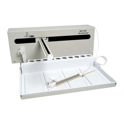
Figure 1-1. Front view of ASX-520 Autosampler.
2. Remove the two Kynar thumbscrews from the Y-axis home block (Figure 1-2).
Figure 1-2. View of Y- axis home block with Kynar thumbscrews.
Guide to installing the splash guard and two piece shield on the ASX-520 and ASX-520HS Autosamplers
3
Figure 1-3. Z-drive removed from arm assembly.
3. Remove the whole Z-drive assembly from the arm by pulling the whole Z-drive assembly
forward and off the autosampler arm (Figure 1-3).
Figure 1-4. View of rinse station.
4. Once the Z-drive assembly is removed, remove the rinse station (Figure 1-4). Turn the rinse
station ¼ turn counter-clockwise while pulling up. Also, the tubing located at the bottom of
rinse station will have to be removed or moved aside (Figure 1-5).
Guide to installing the splash guard and two piece shield on the ASX-520 and ASX-520HS Autosamplers
4
Figure 1-5. View of rinse station removed from the front cover.
5. The autosampler tray should then be removed. Lift up the tray and pull out (Figure 1-6).
Figure 1-6. Removing the tray.
Guide to installing the splash guard and two piece shield on the ASX-520 and ASX-520HS Autosamplers
5
Figure 1-7. Front view of ASX-520 Autosampler showing front cover screws.
6. Next, the front cover needs to be removed. Remove the four corner screws (Figure 1-7).
7. The front cover can be removed by lifting it slightly and pulling forward (Figure 1-8).
Figure 1-8. View of ASX-520 Autosampler with the front cover being removed.
Guide to installing the splash guard and two piece shield on the ASX-520 and ASX-520HS Autosamplers
6
Figure 1-9. View of inner shield inside the ASX-520 Autosampler.
8. The five screws that hold the inner shield will have to be removed. Move the Y-axis
assembly all the way to the left (Figure 1-9).
9. The inner shield can be removed by lifting it up while pulling forward (Figure 1-10).
Figure 1-10. Removal of inner shield.
Guide to installing the splash guard and two piece shield on the ASX-520 and ASX-520HS Autosamplers
7
Figure 1-11. View of ASX-520 with inner shield removed.
Removing the carriage cable
10. Pull out the ribbon cable from the main board to the carriage (Figure 1-12).
Figure 1-12. Main board with ribbon cable.
11. Install the new 31 inch ribbon cable as shown in Figure 1-12 with the red strip towards the
back of the Autosampler. Then route the cable to the left as shown in Figure 1-13.
**Caution** Make sure the cable does not cover IC U4 as this will produce unwanted results.
Figure 1-13. 31 inch ribbon cable installation.
Guide to installing the splash guard and two piece shield on the ASX-520 and ASX-520HS Autosamplers
8
Installing the splash guard & two piece shield
12. Install the splash guard. Begin by sliding the right side of the splash guard in the middle of
the instrument. The material is flexible and you will need to maneuver and bend it until it is in
place. Make sure that the ribbon cable is fed through the left side of the splash as shown in
Figure 1-13. The top part of the splash guard gets tucked under the top lip of the
Autosampler’s outer case. The bottom of the splash guard sits outside of the lower lip of the
Autosampler’s case.
13. Install the lower half of the two piece shield as shown in figure 1-14. Note the routing of the
carriage ribbon cable.
Figure 1-14. Ribbon cable routing and lower half of two piece shield.
14. Install the top shield half of the shield kit. Assemble the shield by screwing the top half of the
shield to the bottom half using two of the 6-32X1/4 inch screws provided in the kit.
Figure 1-15. Assembled shield kit.
15. Finish attaching the shield assembly to the unit by installing the four screws that hold the
shield to the back of the Autosampler. The lower right screw of the old shield will not be used
with this installation. Some manual adjustment may be necessary if the carriage assembly
hits the left screw of the bottom half of the shield assembly. The manual adjustment consists
Guide to installing the splash guard and two piece shield on the ASX-520 and ASX-520HS Autosamplers
9
of applying enough pressure to the bottom left screw to displace the shield out of the carriage
path.
16. Plug in the top end of the ribbon cable to the carriage assembly as shown in Figure1-16
Figure 1-16. Ribbon cable connection to carriage assembly.
17. Reverse instructions 7 through 1 to complete the installation.
When replacing the ribbon cable make sure that no pins are bent and all the pins are in
the board connector. Improper connections could result in damage to the main board.
WARNING

Other manuals for ASX-520

2

This manual suits for next models

1

Other CETAC Laboratory Equipment manuals
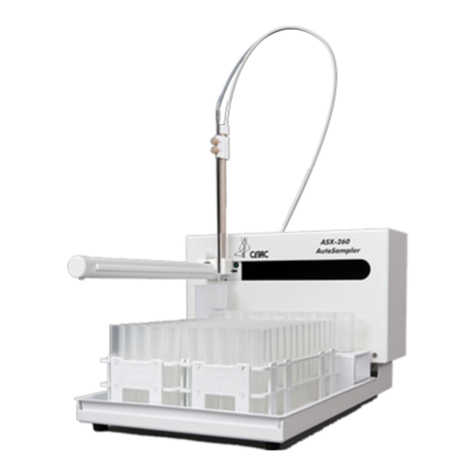
CETAC ASX-260 User manual

CETAC

CETAC ASX-260 User manual

CETAC LSX-213 User manual

CETAC

CETAC LSX-213 User manual

CETAC ASX-520 Use and care manual

CETAC

CETAC ASX-520 Use and care manual

CETAC ASXpress User manual

CETAC

CETAC ASXpress User manual

CETAC ASX-510 Guide

CETAC

CETAC ASX-510 Guide

CETAC ASX-500 Series User manual

CETAC

CETAC ASX-500 Series User manual

CETAC ASX-510 Guide

CETAC

CETAC ASX-510 Guide

CETAC ASXPRESS PLUS User manual

CETAC

CETAC ASXPRESS PLUS User manual

CETAC ASX-520 User manual

CETAC

CETAC ASX-520 User manual
CETAC ASXPRESS PLUS User manual

CETAC

CETAC ASXPRESS PLUS User manual
CETAC ASX-1400 User manual

CETAC

CETAC ASX-1400 User manual

Popular Laboratory Equipment manuals by other brands

PerkinElmer Wallac 1420 user manual

PerkinElmer

PerkinElmer Wallac 1420 user manual

SynOptics SYNBIOSIS aCOLyte 3 HD quick guide

SynOptics

SynOptics SYNBIOSIS aCOLyte 3 HD quick guide

Retsch SR 300 manual

Retsch

Retsch SR 300 manual

Grant QBA Series operating manual

Grant

Grant QBA Series operating manual

Planer 370-M Series Instructions for use

Planer

Planer 370-M Series Instructions for use

Quincy lab AF Series operating manual

Quincy lab

Quincy lab AF Series operating manual

VWR AVANTOR E-BURETTE instruction manual

VWR

VWR AVANTOR E-BURETTE instruction manual

SCHOTT ColdVision user manual

SCHOTT

SCHOTT ColdVision user manual

Thermo IEC Centra-CL2 instruction manual

Thermo IEC

Thermo IEC Centra-CL2 instruction manual

Millipore ReadyStream quick guide

Millipore

Millipore ReadyStream quick guide

Santai Technologies SepaBean Hardware manual

Santai Technologies

Santai Technologies SepaBean Hardware manual

HTL DISCOVERY Comfort DV8-10 instruction manual

HTL

HTL DISCOVERY Comfort DV8-10 instruction manual

Velp Scientifica AREX-6 How to connect

Velp Scientifica

Velp Scientifica AREX-6 How to connect

BioLAB BCBS-103 Operation manual

BioLAB

BioLAB BCBS-103 Operation manual

Agilent Technologies Agilent 33500 Series user guide

Agilent Technologies

Agilent Technologies Agilent 33500 Series user guide

SKF 226400 E Series Instructions for use

SKF

SKF 226400 E Series Instructions for use

Metrohm 717 Instructions for use

Metrohm

Metrohm 717 Instructions for use

Steris AMSCO 30 Series Operator's manual

Steris

Steris AMSCO 30 Series Operator's manual

manuals.online logo
manuals.online logoBrands
  • About & Mission
  • Contact us
  • Privacy Policy
  • Terms and Conditions

Copyright 2025 Manuals.Online. All Rights Reserved.